Page 1694 of 2890
 When tester indicates 12 volts when its probe reaches
point“A”, a broken circuit occurs between point“A”and the
negative terminal. Slowly move tester probe toward the
negative termi")
G6M0137
4) When tester indicates 12 volts when its probe reaches
point“A”, a broken circuit occurs between point“A”and the
negative terminal. Slowly move tester probe toward the
negative terminal while contacting it on heat wire to locate
point where tester indication changes abruptly (0 volts).
This is the point where a broken circuit occurs.
When tester indicates 0 volts when its probe reaches point
“A”, a broken circuit occurs between point“A”and the posi-
tive terminal. Locate a point where tester indication
changes abruptly (12 volts) while slowly moving tester
probe toward the positive terminal.
G6M0138
C: REPAIR
1) Clean broken wire and its surrounding area.
2) Cut off slit on (used) thin film by 0.5 mm (0.020 in) width
and 10 mm (0.39 in) length.
3) Place the slit on glass along the broken wire, and
deposit conductive silver composition (DUPONT No. 4817)
on the broken portion.
4) Dry out the deposited portion.
5) Inspect the repaired wire for continuity.
B6M0120
13. Combination Meter
A: REMOVAL AND INSTALLATION
1. COMBINATION METER
1) Move steering wheel fully down.
2) Remove screws which secure meter visor.
3) Remove visor from instrument panel.
4) Disconnect connectors from meter visor.
B6M0121
5) Remove screws which secure combination meter, and
pull combination meter out.
6) Disconnect connectors from back of combination meter.
CAUTION:
When installing combination meter, be sure to connect
connectors to backside of combination meter.
33
6-2SERVICE PROCEDURE
12. Rear Window Defogger - 13. Combination Meter
Page 1845 of 2890
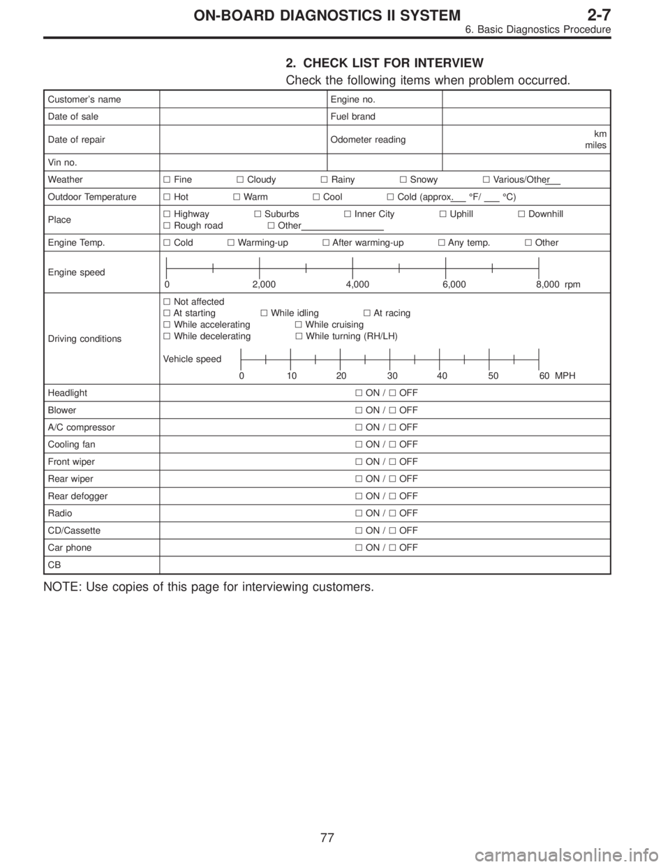
2. CHECK LIST FOR INTERVIEW
Check the following items when problem occurred.
Customer’s name Engine no.
Date of sale Fuel brand
Date of repair Odometer readingkm
miles
Vin no.
Weather�Fine�Cloudy�Rainy�Snowy�Various/Other
Outdoor Temperature�Hot�Warm�Cool�Cold (approx.°F/°C)
Place�Highway�Suburbs�Inner City�Uphill�Downhill
�Rough road�Other
Engine Temp.�Cold�Warming-up�After warming-up�Any temp.�Other
Engine speed
0 2,000 4,000 6,000 8,000 rpm
Driving conditions�Not affected
�At starting�While idling�At racing
�While accelerating�While cruising
�While decelerating�While turning (RH/LH)
Vehicle speed
0 102030405060MPH
Headlight�ON /�OFF
Blower�ON /�OFF
A/C compressor�ON /�OFF
Cooling fan�ON /�OFF
Front wiper�ON /�OFF
Rear wiper�ON /�OFF
Rear defogger�ON /�OFF
Radio�ON /�OFF
CD/Cassette�ON /�OFF
Car phone�ON /�OFF
CB
NOTE: Use copies of this page for interviewing customers.
77
2-7ON-BOARD DIAGNOSTICS II SYSTEM
6. Basic Diagnostics Procedure
Page 2735 of 2890
 The table below lists the nominal sectional areas and
allowable currents of the wires.
Nominal
sectional area
mm
2
No. of strands/
strand diameterOutside
diameter of
finished wiring
mmAllowable
cur")
8) The table below lists the nominal sectional areas and
allowable currents of the wires.
Nominal
sectional area
mm
2
No. of strands/
strand diameterOutside
diameter of
finished wiring
mmAllowable
current
Amps/40°C
0.3 7/0.26 1.8 7
0.5 7/0.32 2.2 (or 2.0) 12
0.75 30/0.18 2.6 (or 2.4) 16
0.85 11/0.32 2.4 (or 2.2) 16
1.25 16/0.32 2.7 (or 2.5) 21
2 26/0.32 3.1 (or 2.9) 28
3 41/0.32 3.8 (or 3.6) 38
5 65/0.32 4.6 (or 4.4) 51
8 50/0.45 5.5 67
CAUTION:
When replacing or repairing a wire, be sure to use the
same size and type of the wire which was originally
used.
NOTE:
�The allowable current in the above table indicates the
tolerable amperage of each wire at an ambient tempera-
ture of 40°C (104°F).
�The allowable current changes with ambient tempera-
ture. Also, it changes if a bundle of more than two wires is
used.
G6M0203
9) Each unit is directly grounded to the body or indirectly
grounds through a harness ground terminal. Different sym-
bols are used in the wiring diagram to identify the two
grounding systems.
The ground points shown in the wiring diagram refer to the
following:
�GBBody ground
�GEEngine ground
�GRRadio ground
�GDRear defogger ground
All wiring harnesses are provided with a ground point which
should be securely connected.
5
6-3WIRING DIAGRAM
1. General Description
Page 2737 of 2890
G6M0205
11) Each connector number shown in the wiring diagram
corresponds to that in the wiring harness. The location of
each connector in the actual vehicle is determined by read-
ing the first character of the connector (for example, a“F”
for F8,“i”for i16, etc.) and the type of wiring harness.
The first character of each connector number refers to the
area or system of the vehicle, as indicated in table below.
Symbol Wiring harness and Cord
F Front wiring harness
B Bulkhead wiring harness
E Engine wiring harness
T Transmission cord
D Door cord LH & RH, Rear gate cord
I Instrument panel wiring harness
RRear wiring harness, Rear defogger cord
Room light cord,
Fuel tank cord,
Sunroof cord,
Trunk lid cord
P Floor wiring harness
7
6-3WIRING DIAGRAM
1. General Description
Page 2750 of 2890

MB-2 Power window circuit breaker
MB-3Engine control module
Fuel pump relay
Main relay
OBD-II service connector
MB-4 A/C relay holder
MB-5 He")
No. Load
MB-1Fuse holder (Rear power supply & seat
heater)
MB-2 Power window circuit breaker
MB-3Engine control module
Fuel pump relay
Main relay
OBD-II service connector
MB-4 A/C relay holder
MB-5 Headlight alarm relay (with security)
MB-6 Headlight LH
MB-7Daytime running light control module
Diode (Lighting)
Diode (Security)
Lighting switch
MB-8Combination meter
Front fog light switch
Headlight RH
Front fog light relay
MB-9Door lock timer
Headlight alarm relay
Interrupt relay
Radio
Security control module
Security indicator light
Spot light
Room light
Step light
Combination meter
Luggage room light
Trailer connector
Trunk room light
MB-10 A/C relay holder
SBF-6ABS relay box
TCS motor relay
SBF-7 TCS valve relay
ALT-1Combination meter
Daytime running light control module
Diode (TCS)
IG Headlight alarm relay
STCruise control module
Engine control module
Inhibitor switch (AT)
Interrupt relay
Starter interlock relay (MT)
FB-1Front washer motor
Rear washer motor
FB-2 Diode (A/C)
FB-3A/C relay holder
Sub fan motor
FB-4Engine control module
Fuel pump relay
Ignition coil
Transmission control module
FB-5 ABS relay boxNo. Load
FB-6Side marker light LH
Side marker light RH
FB-7 Door lock timer
FB-9 Hazard switch
FB-10AT shift lock control module
Key warning switch
Power antenna
FB-11 Radio
FB-12 Cigarette lighter socket
FB-13Mirror heater
Rear power supply relay
Remote control rearview mirror switch
Security control module
Vanity mirror illumination light
FB-14AT shift lock control module
Combination switch
Front wiper motor
Rear wiper motor
Rear wiper relay
FB-15ABS/TCS control module
Transmission control module
FB-16Rear defogger
Rear defogger condenser
Rear defogger switch
FB-17 Rear defogger switch
FB-18AT shift lock control module
Back-up light switch (MT)
Inhibitor switch (AT)
FB-19 Hazard switch
FB-20A/C switch
Combination meter
Mode control panel
TCS off switch
FB-21 Combination meter (Airbag)
FB-22Blower motor relay
Check connector
Daytime running light control module
Daytime running light relay
FRESH/RECIRC actuator
Hi-beam relay
Power window and sunroof relay
Seat belt timer
FB-23 Airbag control module
20
6-3WIRING DIAGRAM
6. Wiring Diagram
Page 2751 of 2890
No. Load
FB-24 Airbag control module
FB-25 Lighting switch
FB-26 Parking switch
FB-27 Parking switch
FB-28 Illumination light
FB-29 Illumination light
FB-30Pedal stroke switch
Stop light switch
Stop & brake switch
FB-31 Horn relay
FB-32 Blower motor relay
FB-33 Parking switch
FB-34License plate light
Rear combination light LH
Rear combination light RH
Rear finisher light LH
Rear finisher light RH
FB-35ABS control module
ABS/TCS control module
TCS valve relay
Cruise control main switch
Cruise control module
FB-36 Front fog light relay
21
6-3WIRING DIAGRAM
6. Wiring Diagram
Page 2754 of 2890

Lighting switch
MB")
No. Load
MB-2 Power window circuit breaker
MB-3Engine control module
Fuel pump relay
Main relay
OBD-II service connector
MB-4 A/C relay holder
MB-6 Headlight LH
MB-7Diode (Lighting)
Lighting switch
MB-8Combination meter
Headlight RH
MB-9Combination meter
Door lock timer
Luggage room light
Radio
Room light
MB-10 A/C relay holder
ALT-1 Combination meter
IG A/C relay holder
STCruise control module
Engine control module
Inhibitor switch
FB-2 Diode (A/C)
FB-3Sub fan motor
Sub fan relay-2
FB-4Engine control module
Fuel pump relay
Ignition coil
Transmission control module
FB-6Side marker light LH
Side marker light RH
FB-7 Door lock timer
FB-9 Hazard switch
FB-10AT shift lock control module
Key warning switch
Power antenna
FB-11 Radio
FB-12 Cigarette lighter
FB-13 Remote control rearview mirror switch
FB-14AT shift lock control module
Combination switch
Front washer motor
Front wiper motor
Rear washer motor
Rear wiper motor
Rear wiper relay
FB-15 Transmission control moduleNo. Load
FB-16Rear defogger
Rear defogger condenser
Rear defogger switch
FB-17 Rear defogger switch
FB-18AT shift lock control module
Inhibitor switch
FB-19 Hazard switch
FB-20Combination meter
Mode control panel
FB-21 Combination meter (Airbag)
FB-22Blower motor relay
Check connector
FRESH/RECIRC actuator
Mode actuator
Power window relay
Seat belt timer
FB-23 Airbag control module
FB-24 Airbag control module
FB-25 Lighting switch
FB-26 Parking switch
FB-27 Parking switch
FB-28 Illumination light
FB-29 Illumination light
FB-30Stop light switch
Stop & brake switch
FB-31 Horn relay
FB-32 Blower motor relay
FB-33 Parking switch
FB-34License plate light LH
License plate light RH
Rear combination light LH
Rear combination light RH
Rear finisher light LH
Rear finisher light RH
FB-35Cruise control main switch
Cruise control module
24
6-3WIRING DIAGRAM
6. Wiring Diagram
Page 2814 of 2890
24. REAR WINDOW DEFOGGER SYSTEM
�LHD model
BU52-01
84
6-3WIRING DIAGRAM
6. Wiring Diagram
 Each connector number shown in the wiring diagram
corresponds to that in the wiring harness. The location of
each connector in the actual vehicle is determined by read-
ing the first chara")