Page 168 of 2890

SUPPLEMENTAL
RESTRAINT
SYSTEM
(ELECTRIC
SENSOR
TYPE)
[T5P1]
5-5b
5
.
Diagnostics
Chart
with
Trouble
Code
1
.
AIRBAG
COMPONENT
PARTS
APPEARANCE
INSPECTION
1)
Conduct
on-board
diagnostic
and
call
up
trouble
codes
stored
in
memory
.
<
Ref
.
to
[T4B0]
.*2>
2)
Select
trouble
code
required
to
check
airbag
compo-
nent
parts
from
those
listed
in
table
and
reproduce
symp-
tom
.
Trouble
codes
Check
parts
Refer
to
5-5
:
Airbag
module
(Passenger)
W3A2
Sri
04*
Airbag
main
harness
W5A0
*1
Airbag
control
module
W6A0
tr2
e
Fuse
No
.
8
T5D3
Sri
11
*
Airbag
main
harness
W5A0
*1
Airbag
control
module
W6A0
x`r2
Body
harness
-
Roll
connector
W7A0
*2
9
Airbag
module
(Driver)
W3A1
x`ri
12
Airbag
main
harness
W5A0
Sri
Airbag
control
module
W6A0
*2
Airbag
module
(Driver)
W3A1
Sri
o
Roll
connector
W7A0
*2
13
Airbag
main
harness
W5A0
*1
Airbag
control
module
W6A0
*2
21
e
Airbag
control
module
W6A0
*2
Airbag
module
(Passenger)
W3A2*1
22
9
Airbag
main
harness
W5A0
Sri
Airbag
control
module
W6A0*2
33
*
Airbag
control
module
W6A0
x`r2
Airbag
main
harness
W5A0
*1
34*
Airbag
module
(Passenger)
W3A2
*1
Airbag
control
module
W6A0*2
Airbag
module
(Driver)
W3A1
Sri
9
Roll
connector
W7A0
ir2
41
r
Airbag
main
harness
W5A0
Sri
Airbag
control
module
W6A0*2
Airbag
module
(Passenger)
W3A2
Sri
42
*
Airbag
main
harness
W5A0
*i
Airbag
control
module
W6A0*2
Airbag
module
(Driver)
W3A1
*1
e
Roil
connector
W7A0
*2
43
Airbag
main
harness
W5A0
x`ri
Airbag
control
module
W6A0
*2
39
Page 169 of 2890

5-5b
[T5p2]
SUPPLEMENTAL
RESTRAINT
SYSTEM
(ELECTRIC
SENSOR
TYPE)
5
.
Diagnostics
Chart
with
Trouble
Code
v
4U
G5M0461
I
3)
Conduct
appearance
inspection
on
parts
selected
.
CHECK
:
Is
there
anything
unusualabout
the
appear-
ance
of
airbag
component
parts?
ves
:
Replace
faulty
airbag
component
parts
.
No
:
Go
to
step
2
.
NOTE
:
Also
check
connector
terminals,
wiring
harness,
case,
etc
.
for
damage
.
2
.
AIRBAG
COMPONENT
PARTS
VIBRATION
INSPECTION
1)
Gently
shake
check
parts
(to
determine
faults
.)
.
2)
To
check
airbag
module
or
roll
connector,
turn
and
tilt
steering
wheel
CAUTION
:
Do
not
shake
or
vibrate
airbag
control
module
.
CHECK
:
Does
the
component
malfunction
again
when
shaking?
Replace
faulty
airbag
component
parts
.
No
:
Go
to
step
3
.
3
.
SHOWERING
INSPECTION
TO
BODY
Spray
water
on
vehicle
body
.
CAUTION
:
Do
not
directly
spraywater
on
airbag
components
.
CHECK
:
Does
water
leak
into
the
passenger
compart-
ment
when
showering
vehicle?
Replace
faulty
airbag
component
parts
.
No
:
Clear
memory
.
NOTE
:
Also
check
wiring
harnesses
as
water
may
leak
along
them
and
get
airbag
component
parts
wet
.
40
Page 170 of 2890

SUPPLEMENTAL
RESTRAINT
SYSTEM
(ELECTRIC
SENSOR
TYPE)
[T5(a1]
5-5b
5
.
Diagnostics
Chart
with
Trouble
Code
Q
:
WARNING
LIGHTINDICATES
TROUBLE
CODE,
THEN
NORMAL
CODE
.
-
FLASHING
NORMAL
CODE
.
-
DIAGNOSIS
:
"
Airbag
connector
is
faulty
.
"
Fuse
No
.
16
is
blown
.
"
Airbag
.
main
harness
is
faulty
.
"
Airbag
control
module
is
faulty
.
"
Body
harness
is
faulty
.
1
1
.
Airbag
connector
appearance
inspection
1
2
.
Atrbag
connector
vibration
inspection
3
.
Showering
inspection
to
body
4
.
Fuse
No
.
16,
airbag
main
harness,
airbag
control
module,
body
harness
appearance
inspection
5
.
Fuse
No
.
16,
airbag
main
harness,
body
harness
vibration
inspection
1
6
.
Showering
inspectionto
body
1
7
.
Warning
light
illumination
check
CAUTION
:
Before
performing
diagnostics
on
airbag
system,
turn
ignition
switch
"OFF",
disconnect
battery
ground
cable,
and
then
wait
at
least
20
seconds
.
1
.
AIRBAG
CONNECTOR
APPEARANCE
INSPECTION
Conduct
appearance
inspection
on
airbag
connectors
(AB2)
through
(AB8)
.
<
Ref
.
to
5-5
[T100]
.*2
>
CHECK
:
Is
thereanything
unusualabout
the
appear-
ance
of
connectors(AB2)
through
(AB8)?
,rES
:
Replace
faulty
airbag
component
parts
.
No
:
Go
to
step
2
.
NOTE
:
Check
terminals,
case
and
wiring
harnesses
for
damage
.
41
Page 171 of 2890

5-5b
[T5G12]
SUPPLEMENTAL
RESTRAINT
SYSTEM
(ELECTRIC
SENSOR
TYPE)
5
.
Diagnostics
Chart
with
Trouble
Code
2
.
AIRBAG
CONNECTOR
VIBRATION
INSPECTION
Conduct
vibration
inspection
on
airbag
connectors
(AB2)
through
(AB8)
.
<
Ref
.
to
5-5
[T100]
.*2
>
CHECK
:
Do
the
connectors
(AB2)
through
(AB8)
mal-
function
again
when
shaking?
Replace
faulty
airbag
component
parts
.
No
:
Go
to
step
3
.
NOTE
:
Gently
shake
each
airbag
connector
.
3
.
SHOWERING
INSPECTION
TO
BODY
Spray
water
on
vehicle
body
.
CAUTION
:
Do
not
directly
spray
water
on
airbag
components
.
CHECK
:
Does
water
leak
into
the
passenger
compart-
ment
when
showering
vehicle?
vES
:
Replace
faulty
airbag
component
parts
.
No
:
Go
to
step
4
.
NOTE
:
If
leaks
are
noted,also
check
wiring
harnesses
as
water
may
leak
along
them
and
wet
airbag
connectors
.
4
.
FUSENo
.
16,
AIRBAGMAINHARNESS,
AIRBAG
CONTROL
MODULE,
BODY
HARNESS
APPEARANCE
INSPECTION
Conduct
appearance
inspection
on
fuse
No
.
16
<
Ref
.
to
[T5L3].*1
>,
airbag
main
harness
<
Ref
.
to
[W5A0]
.*1
>,
airbag
control
module
.
to
[W6AOJ
.*2>
and
body
harness
.
CHECK
:
Is
there
anything
unusualabout
the
appear-
ance
of
fuse
No
.
16,
airbag
main
harness,
airbag
control
module
or
body
harness?
,rES
:
Replace
faulty
airbag
component
parts
.
No
:
Go
to
step
5
.
NOTE
:
Also
check
connectors,
terminals,
wiring
harness
and
case
for
damage
.
42
Page 188 of 2890
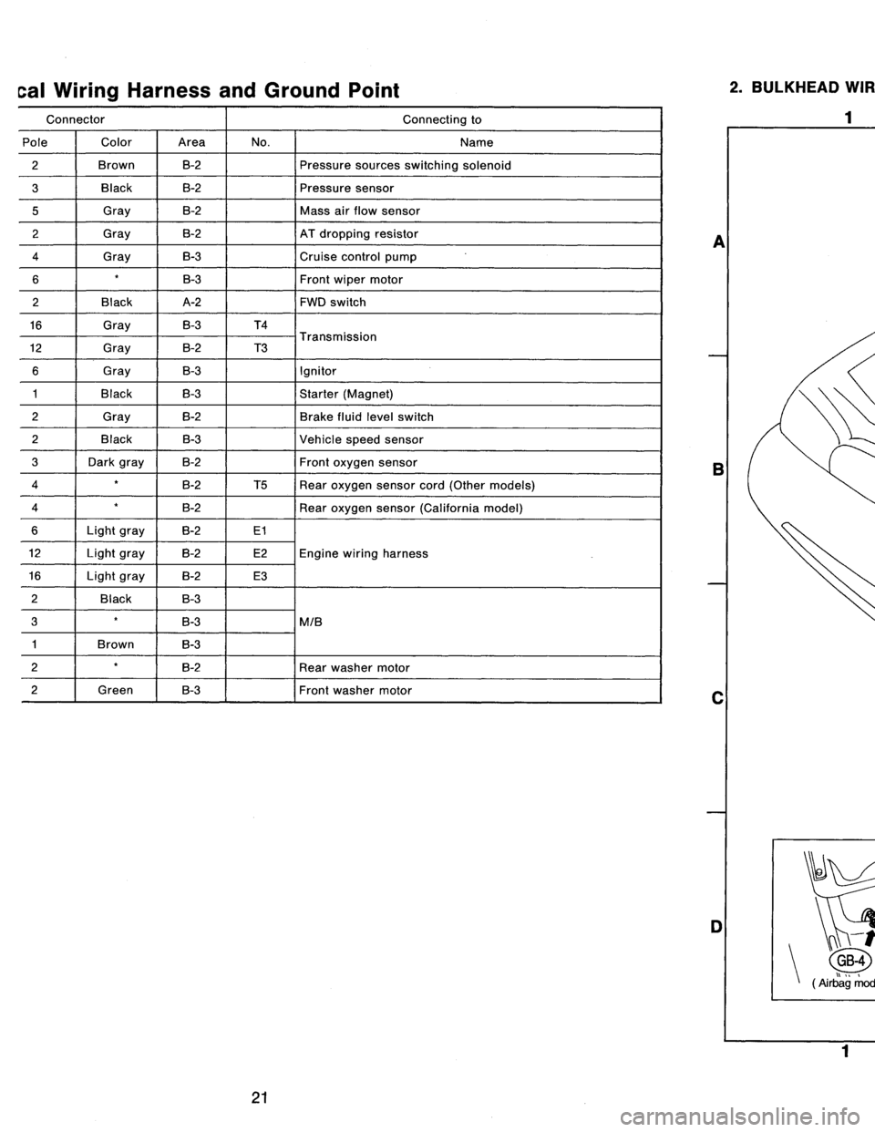
cal
Wiring
Harness
and
Ground
Point
Connector
Connecting
to
Pole
Color
Area
No
.
Name
2
Brown
B-2
Pressure
sources
switching
solenoid
3
Black
B-2
Pressure
sensor
5
Gray
B-2
Mass
air
flow
sensor
2
Gray
B-2
AT
dropping
resistor
4
Gray
B-3
Cruise
control
pump
6B-3Front
wipermotor
2
Black
A-2
FWD
switch
16
Gray
B-3
T4
T
i
12
Gray
B-2
T3
ransmiss
on
6
Gray
B-3
Ignitor
1
Black
B-3
Starter
(Magnet)
2
Gray
B-2
Brake
fluid
level
switch
2
Black
B-3
Vehicle
speed
sensor
3
Dark
gray
B-2
Front
oxygen
sensor
4
B-2
T5
Rear
oxygen
sensor
cord
(Other
models)
4
B-2
Rear
oxygen
sensor
(California
model)
6Light
gray
B-2
E1
12Light
gray
B-2
E2Engine
wiring
harness
16Light
gray
B-2
E3
2
Back
B-3
3
B-3
MIB
1
Brown
B-3
2B-2
Rear
washer
motor
2f
Green
B-3Front
washer
motor
2
.
BULKHEAD
WIRING
HARNESS
AND
GROUND
POINT
(IN
ENGINE
ROOM)
2
I
a
B
C
-r
t
n
GB-4
GB-5
(
rbag
mode
)
B6M0086B
D
1
3
4
4
[D802]
B6M0587A
A
B
C
D
21
Page 189 of 2890
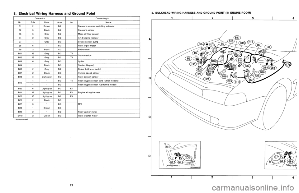
8
.
Electrical
Wiring
Harness
and
Ground
Point
Connector
Connecting
to
No
.
Pole
Color
Area
No
.
Name
131
2
Brown
B-2
Pressure
sources
switching
solenoid
B2
3
Black
B-2
Pressure
sensor
B3
5
Gray
B-2
Mass
air
slow
sensor
B4
2
Gray
B-2
AT
dropping
resistor
B7
4
Gray
B-3
Cruise
control
pump
B8
6B-3Front
wiper
motor
B9
2
Black
A-2
FWD
switch
B11
16
Gray
B-3
T4
T
B12
12
Gray
B-2
T3
ransmission
B13
6
Gray
B-3
Ignitor
B14
1
Black
B-3
Starter
(Magnet)
B16
2
Gray
B-2
Brake
fluid
level
switch
B17
2
Black
B-3
Vehicle
speed
sensor
B18
3
Dark
gray
B-2Front
oxygen
sensor
4B-2
T5Rear
oxygen
sensor
cord(Other
models)
B19
4B-2
Rear
oxygen
sensor
(California
model)
B20
6Light
gray
B-2El
821
12
Light
gray
B-2
E2Engine
wiring
harness
B22
16
Light
gray
B-2
E3
B26
2
Black
B-3
B27
3B-3
MIB
B28
1
Brown
B-3
B29
2B-2
Rear
washer
motor
B110
~
2
f
Green
B-3
~
Front
washer
motor
`
:
Non-colored
2
.
BULKHEAD
WIRING
HARNESS
AND
GROUND
POINT
(IN
ENGINE
ROOM)
1
2
3
a
E
C
DI
Yi-t
~
GB-4GB-5
(Air
`bag
model
(
Airbag
model
~rrE
1
23
4
21
Page 190 of 2890
r
Connecting
to
)r
Area
No
.
Name
C-4
D1
Front
doorcord
RH
ow
C-4
ABi
SRS
(Airbag)
harness
;k
C-4
Turn
&
hazard
module
.k
C-3
i1
C-3
i2
instrument
panel
wiring
un
C-3
i3
harness
e
C-3
i4
y
C-3
OBD-IIservice
connector
C-3
Power
window
circuit
breaker
C-3
Power
window
relay
;k
C-3
Illuminationcontrol
module
C-3
Seat
belt
timer
;n
B-4
Fuel
pump
relay
vn
B-4
Main
relay
;k
B-4
Horn
relay
B-4
Blower
relay
y
C-4
FIB
y
C-4
B-3
Shield
joint
connector
(AT)
.k
B-3
:k
B-3
Transmission
control
module
.k
B-3
:k
B-3
Shift-lock
control
module
B-4F44
i
h
B-4F45
Front
w
ring
arness
.k
B-3
Stop
light
switch
,k
B-3
Stop
8
brake
switch
(Withcruise
control)
:k
8-3
Cruise
control
sub
switch
Connector
Connecting
to
No
.
Pole
Color
Area
No
.
Name
869
11
Black
C-3
B70
9
C-3
Combination
switch
B71
8
8-3
B72
6
Black
C-3
Ignition
switch
B73
2
Black
B-3
Key
lock
solenoid
B74
2
Black
B-3
Key
warning
switch
B75
2
Green
B-2
876
T
d
B76
2
Green
8-2
875
e
connector
est
mo
877
7
B-2
Mode
actuator
B78
9
Yellow
B-2
Data
link
connector
B79
14
Gray
C-2
Check
connector
BBO
4
Blue
B-2
i20
Instrument
panel
wiring
harness
B81
1
x
2
B-2
Diagnosis
terminal
(Ground)
B82
6
Black
B-2
Diagnosisconnector
BB3
4
C-1
Shield
joint
connector
(EIG)
BBQ
96Lightblue
C-2
Engine
control
module
B85
4
Brown
B-3
Diode
(Lighting)
B86
4
Black
B-1
Blower
motor
resistor
887
2
Black
B-1
Blower
motor
888
3
Black
B-1
Evaporatorthermoswitch
B90
2
Green
B-4
R50
Room
light
cord
B91
5
B-1
FRESHIRECIRC
actuator
B92
8
B-1
Door
lock
timer
894
20
Black
B-1
Cruise
control
module
B97
56
B-4
R1
Rear
wiring
harness
(S.M
.J
.)
B101
24
B-1
D11
Front
door
cord
LH
8111
3
Gray
C-4FIB
`
:
Non-colored
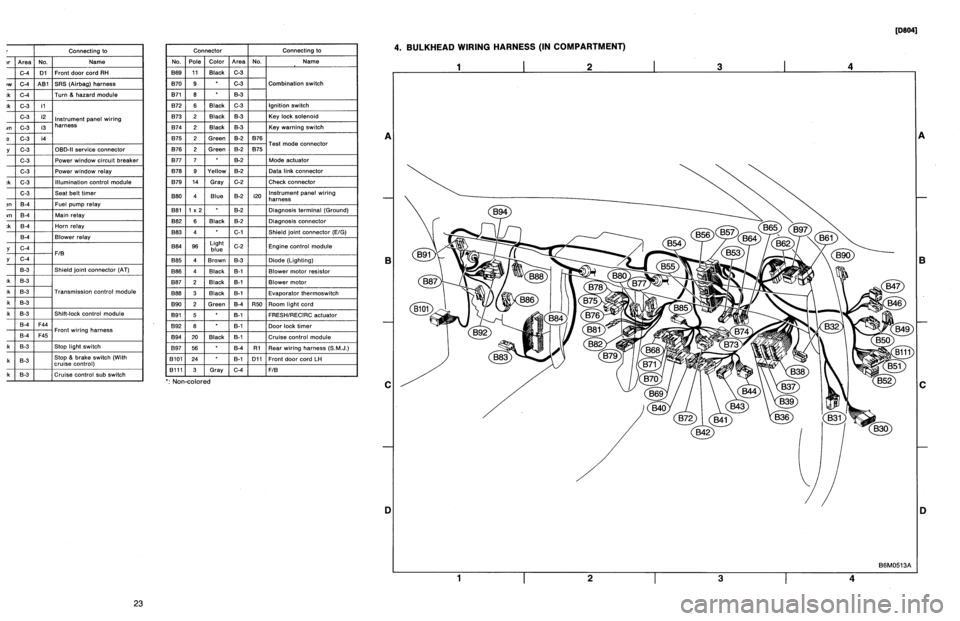
4
.
BULKHEAD
WIRING
HARNESS
(IN
COMPARTMENT)
1
I
2
I
3
I
4
A
B
C
D
1
I
2
I
3
I
4
[oeo41
B6M0513A
A
B
C
iJ
23
Page 191 of 2890
Connector
Connecting
to
No
.
Pole
Color
Area
No
.
Name
830
24
C-4
D1
Front
door
cord
RH
831
7
Yellow
C-4
A81
SRS
(Airbag)
harness
B32
3
Black
C-4
Turn
&
hazard
module
B36
22
Black
C-3
i1
B37
22
C-3
i2
Instrument
panel
wiring
B38
22
Brown
C-3
i3
harness
B39
20Blue
C-3
i4
B40
16
Gray
C-3
OBD-II
service
connector
B41
2
C-3
Power
window
circuit
breaker
842
4
C-3
Power
window
relay
B43
6
Black
C-3
Illumination
control
module
B44
8
C-3
Seat
belt
timer
B46
4
Green
B-4
Fuel
pump
relay
B47
6
Brown
B-4
Main
relay
B49
3
Black
B-4
Horn
relay
850
4
B-4
Blower
relay
851
11
Gray
C-4
FIB
B52
12
Gray
C-4
853
4
B-3
Shield
joint
connector
(AT)
B54
12
Black
B-3
B55
16
Black
B-3
Transmission
control
module
B56
20
Black
B-3
B57
12
Black
B-3
Shift-lock
control
module
861
B
B-4
F44
B62
20
B-4
F45
Front
wiring
harness
B64
2
Black
B-3
Stop
light
switch
B65
4
Black
B-3
Stop
&
brake
switch(Withcruise
control)
B68
5
i
Black
i
B-3
Cruise
control
sub
switch
Connector
Connecting
to
No
.
Pole
Color
Area
No
.
Name
B69
11
Black
C-3
B70
9
C-3
Combination
switch
B71
8
8-3
B72
6
Black
C-3
Ignition
switch
B73
2
Black
B-3
Key
lock
solenoid
B74
2
Black
B-3
Key
warning
switch
B75
2
Green
B-2
B76
B76
2
Green
&2
B75
Test
mode
connector
B77
7
B-2
Made
actuator
B78
9
Yellow
B-2
Data
link
connector
B79
14
Gray
C-2
Check
connector
B80
4
Blue
B-2
i20
Instrumentpanel
wiring
harness
B81
1
x
2
B-2
Diagnosis
terminal
(Ground)
B82
6
Black
B-2
Diagnosis
connector
B83
4
C-1
Shield
joint
connector
(E!G)
884
96
Light
blue
C-2
Engine
control
module
885
4
Brown
B-3
Diode
(Lighting)
B86
4
Black
B-1
Blower
motor
resistor
887
2
Black
B-1
Blower
motor
B88
3
Black
8-t
Evaporator
thermoswitch
890
2
Green
B-4
R50
Room
light
cord
B91
5B-1
FRESHIRECIRC
actuator
892
8
B-1
Door
lock
timer
B94
20
Black
B-1
Cruise
control
module
B97
56
B-4
R1Rear
wiring
harness
(S
.M
.J
.)
B101
24
B-1
D11
Front
doorcord
LH
13111
3
Gray
C-4
FIB
`
:
Non-colored
4
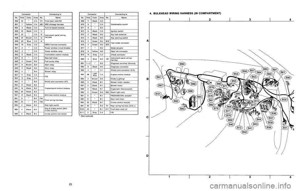
.
BULKHEAD
WIRING
HARNESS
(IN
COMPARTMENT)
A
B
C
1]
4
23