Page 828 of 2890
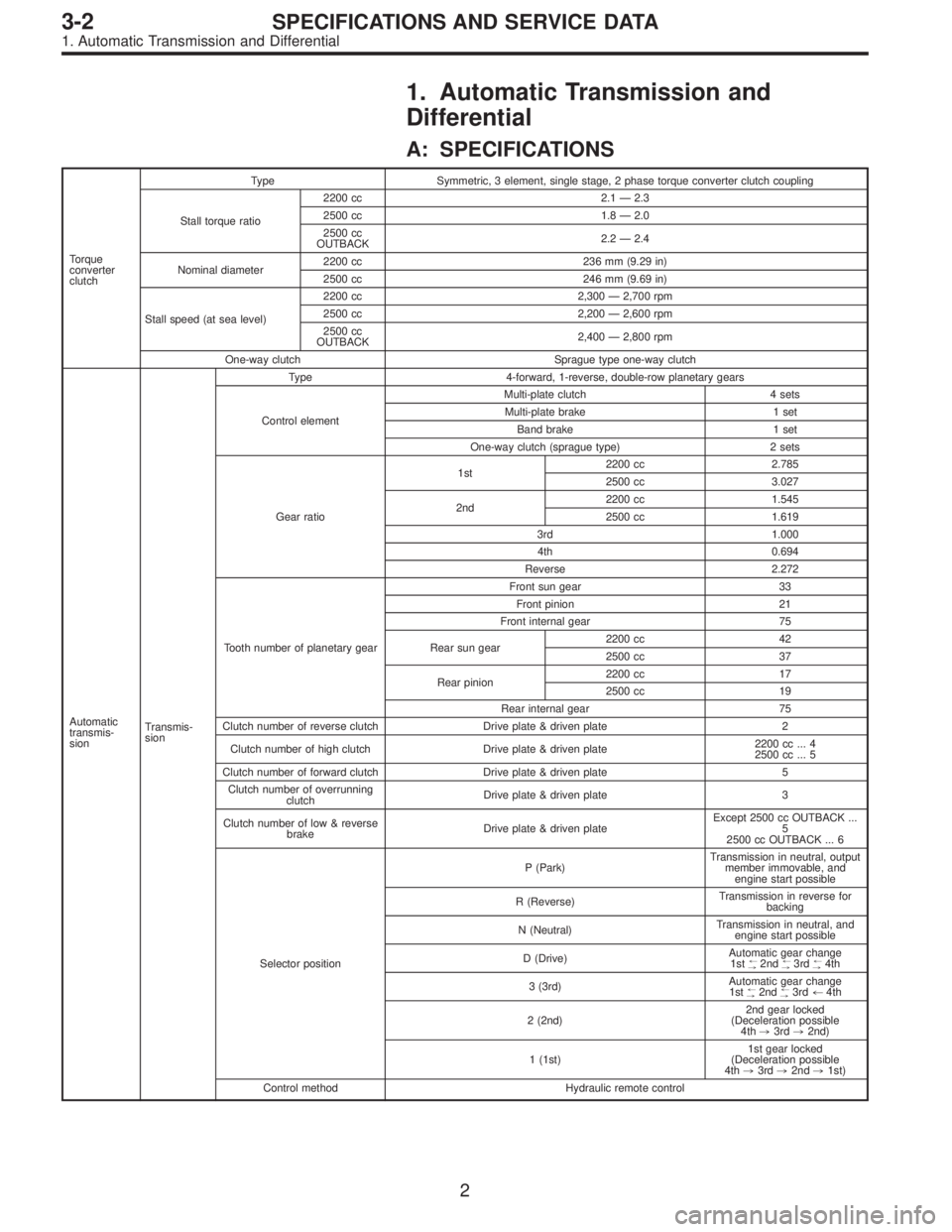
1. Automatic Transmission and
Differential
A: SPECIFICATIONS
Torque
converter
clutchType Symmetric, 3 element, single stage, 2 phase torque converter clutch coupling
Stall torque ratio2200 cc 2.1 — 2.3
2500 cc 1.8 — 2.0
2500 cc
OUTBACK2.2—2.4
Nominal diameter2200 cc 236 mm (9.29 in)
2500 cc 246 mm (9.69 in)
Stall speed (at sea level)2200 cc 2,300 — 2,700 rpm
2500 cc 2,200 — 2,600 rpm
2500 cc
OUTBACK2,400 — 2,800 rpm
One-way clutch Sprague type one-way clutch
Automatic
transmis-
sionTransmis-
sionType 4-forward, 1-reverse, double-row planetary gears
Control elementMulti-plate clutch 4 sets
Multi-plate brake 1 set
Band brake 1 set
One-way clutch (sprague type) 2 sets
Gear ratio1st2200 cc 2.785
2500 cc 3.027
2nd2200 cc 1.545
2500 cc 1.619
3rd 1.000
4th 0.694
Reverse 2.272
Tooth number of planetary gearFront sun gear 33
Front pinion 21
Front internal gear 75
Rear sun gear2200 cc 42
2500 cc 37
Rear pinion2200 cc 17
2500 cc 19
Rear internal gear 75
Clutch number of reverse clutch Drive plate & driven plate 2
Clutch number of high clutch Drive plate & driven plate2200 cc ... 4
2500 cc ... 5
Clutch number of forward clutch Drive plate & driven plate 5
Clutch number of overrunning
clutchDrive plate & driven plate 3
Clutch number of low & reverse
brakeDrive plate & driven plateExcept 2500 cc OUTBACK ...
5
2500 cc OUTBACK ... 6
Selector positionP (Park)Transmission in neutral, output
member immovable, and
engine start possible
R (Reverse)Transmission in reverse for
backing
N (Neutral)Transmission in neutral, and
engine start possible
D (Drive)Automatic gear change
1st
+
,2nd+
,3rd+
,4th
3 (3rd)Automatic gear change
1st
+
,2nd+
,3rd+4th
2 (2nd)2nd gear locked
(Deceleration possible
4th,3rd,2nd)
1 (1st)1st gear locked
(Deceleration possible
4th,3rd,2nd,1st)
Control method Hydraulic remote control
2
3-2SPECIFICATIONS AND SERVICE DATA
1. Automatic Transmission and Differential
Page 836 of 2890
1. Torque Converter Clutch and Case
B3M0104A
�1Pitching stopper bracket
�
2Oil level gauge
�
3O-ring
�
4Oil seal
�
5Snap ring
�
6Washer
�
7Speedometer shaft
�
8Clip
�
9Oil pump shaft
�
10Seal ring
�
11Seal pipe
�
12Speedometer driven gear
�
13Snap ring
�
14Drain plug�
15Oil seal
�
16Harness clip
�
17Torque converter clutch case
�
18Torque converter clutch
�
19O-ring
�
20Input shaft
�
21Gasket
�
22Oil drain pipe
Tightening torque: N⋅m (kg-m, ft-lb)
T1: 18±5 (1.8±0.5, 13.0±3.6)
T2: 41±3 (4.2±0.3, 30.4±2.2)
T3: 44±3 (4.5±0.3, 32.5±2.2)
10
3-2COMPONENT PARTS
1. Torque Converter Clutch and Case
Page 850 of 2890
G3M0283
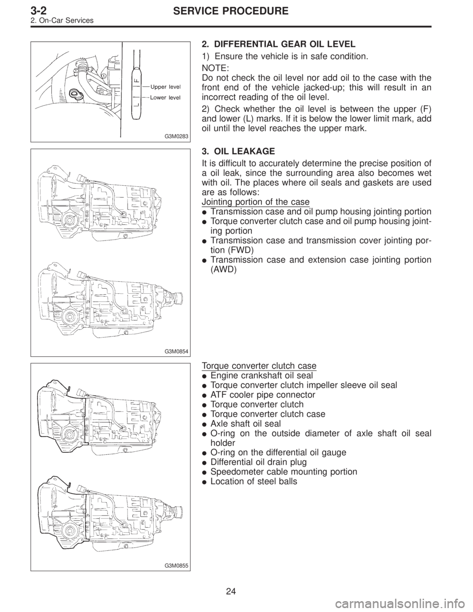
2. DIFFERENTIAL GEAR OIL LEVEL
1) Ensure the vehicle is in safe condition.
NOTE:
Do not check the oil level nor add oil to the case with the
front end of the vehicle jacked-up; this will result in an
incorrect reading of the oil level.
2) Check whether the oil level is between the upper (F)
and lower (L) marks. If it is below the lower limit mark, add
oil until the level reaches the upper mark.
G3M0854
3. OIL LEAKAGE
It is difficult to accurately determine the precise position of
a oil leak, since the surrounding area also becomes wet
with oil. The places where oil seals and gaskets are used
are as follows:
Jointing portion of the case
�Transmission case and oil pump housing jointing portion
�Torque converter clutch case and oil pump housing joint-
ing portion
�Transmission case and transmission cover jointing por-
tion (FWD)
�Transmission case and extension case jointing portion
(AWD)
G3M0855
Torque converter clutch case
�Engine crankshaft oil seal
�Torque converter clutch impeller sleeve oil seal
�ATF cooler pipe connector
�Torque converter clutch
�Torque converter clutch case
�Axle shaft oil seal
�O-ring on the outside diameter of axle shaft oil seal
holder
�O-ring on the differential oil gauge
�Differential oil drain plug
�Speedometer cable mounting portion
�Location of steel balls
24
3-2SERVICE PROCEDURE
2. On-Car Services
Page 864 of 2890
3. Performance Test
A: STALL TEST
1. GENERAL
The stall test is of extreme importance in diagnosing the
condition of the automatic transmission and the engine. It
should be conducted to measure the engine stall speeds in
all shift ranges except the P and N ranges.
Purposes of the stall test:
1) To check the operation of the automatic transmission
clutch.
2) To check the operation of the torque converter clutch.
3) To check engine performance.
2. TEST METHODS
Preparations before test:
�
1Check that throttle valve opens fully.
�
2Check that engine oil level is correct.
�
3Check that coolant level is correct.
�
4Check that ATF level is correct.
�
5Check that differential gear oil level is correct.
�
6Increase ATF temperature to 50 to 80°C (122 to 176°F)
by idling the engine for approximately 30 minutes (with
select lever set to“N”or“P”).
1) Install an engine tachometer at a location visible from
the driver’s compartment and mark the stall speed range
on the tachometer scale.
2) Place the wheel chocks at the front and rear of all
wheels and engage the parking brake.
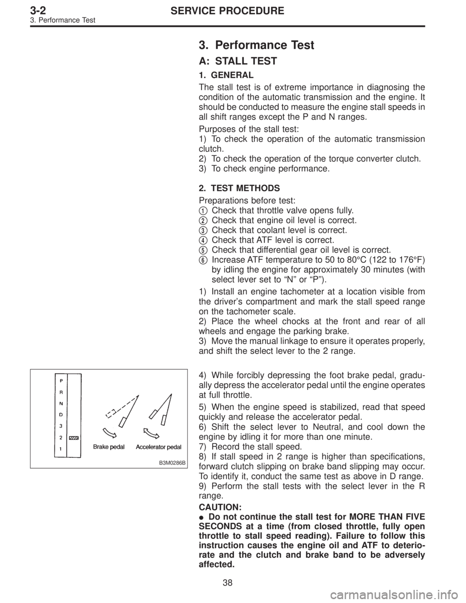
3) Move the manual linkage to ensure it operates properly,
and shift the select lever to the 2 range.
B3M0286B
4) While forcibly depressing the foot brake pedal, gradu-
ally depress the accelerator pedal until the engine operates
at full throttle.
5) When the engine speed is stabilized, read that speed
quickly and release the accelerator pedal.
6) Shift the select lever to Neutral, and cool down the
engine by idling it for more than one minute.
7) Record the stall speed.
8) If stall speed in 2 range is higher than specifications,
forward clutch slipping on brake band slipping may occur.
To identify it, conduct the same test as above in D range.
9) Perform the stall tests with the select lever in the R
range.
CAUTION:
�Do not continue the stall test for MORE THAN FIVE
SECONDS at a time (from closed throttle, fully open
throttle to stall speed reading). Failure to follow this
instruction causes the engine oil and ATF to deterio-
rate and the clutch and brake band to be adversely
affected.
38
3-2SERVICE PROCEDURE
3. Performance Test
Page 865 of 2890
Be sure to cool down the engine for at least one minute
after each stall test with the select lever set in the P or
N range and with the idle speed lower than 1,200 rpm.
�If the stall speed is higher than the specified range,
attempt to finish the stall test in as short a time as
possible, in order to prevent the automatic transmis-
sion from sustaining damage.
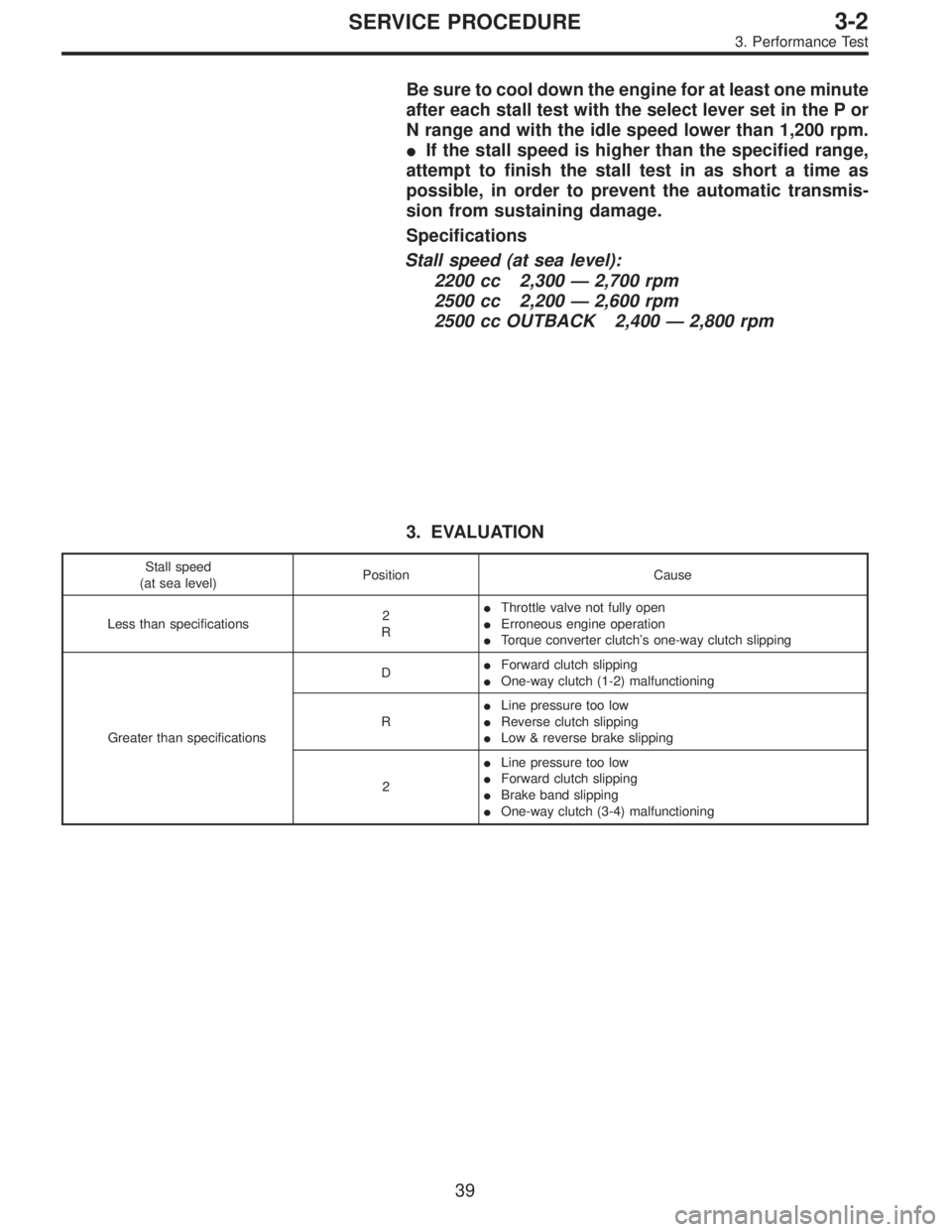
Specifications
Stall speed (at sea level):
2200 cc 2,300 — 2,700 rpm
2500 cc 2,200 — 2,600 rpm
2500 cc OUTBACK 2,400 — 2,800 rpm
3. EVALUATION
Stall speed
(at sea level)Position Cause
Less than specifications2
R�Throttle valve not fully open
�Erroneous engine operation
�Torque converter clutch’s one-way clutch slipping
Greater than specificationsD�Forward clutch slipping
�One-way clutch (1-2) malfunctioning
R�Line pressure too low
�Reverse clutch slipping
�Low & reverse brake slipping
2�Line pressure too low
�Forward clutch slipping
�Brake band slipping
�One-way clutch (3-4) malfunctioning
39
3-2SERVICE PROCEDURE
3. Performance Test
Page 874 of 2890
G3M0871
A: DISASSEMBLY
1. EXTERNAL PARTS
1) Place the transmission unit on a work bench, with the
oil pan facing down.
CAUTION:
Be careful not to bend or damage external parts.
G3M0325
2) Remove the drain plug, and drain differential oil. Tighten
the plug temporarily after draining.
G3M0326
3) Remove the drain plug, and drain automatic transmis-
sion fluid (ATF). Tighten the plug temporarily after draining.
G3M0327
4) Extract the torque converter clutch assembly.
NOTE:
�Extract the torque converter clutch horizontally. Be care-
ful not to scratch the bushing inside the oil pump shaft.
�Note that oil pump shaft also comes out.
G3M0328
5) Remove the input shaft.
48
3-2SERVICE PROCEDURE
4. Overall Transmission
Page 876 of 2890
G3M0874
2. SEPARATION OF EACH SECTION
1) Separation of torque converter clutch case and trans-
mission case sections
CAUTION:
�Be careful not to damage the oil seal and bushing
inside the torque converter clutch case by the oil pump
cover.
�Be careful not to lose the rubber seal.
NOTE:
Separate these cases while tapping lightly on the housing.
G3M0336
2) Separation of transmission case and extension sections
(AWD)
(1) Remove vehicle speed sensor 1.
G3M0337
(2) While pulling the extension slightly, disconnect the
connector for the duty solenoid C (transfer).
CAUTION:
Be careful not to cut the harness.
3) Separate both sections.
G3M0338
3. TRANSMISSION CASE SECTION
1) Remove the reduction drive gear assembly.
G3M0339
2) Remove the reduction driven gear.
(1) Straighten the staked portion, and remove the lock
nut.
NOTE:
Set the range selector lever to“P”.
50
3-2SERVICE PROCEDURE
4. Overall Transmission
Page 883 of 2890
G3M0366
30) Remove the inhibitor switch.
G3M0367
31) Remove the transmission harness.
CAUTION:
Be careful not to damage the cord insulation.
G3M0368
4. TORQUE CONVERTER CLUTCH CASE SECTION
1) Wrap the axle shaft serration with vinyl tape.
2) Remove the differential side retainer with ST.
ST 499787000 WRENCH ASSY
CAUTION:
Hold the differential case assembly by hand to avoid
damaging retainer mounting hole of the torque con-
verter clutch case and speedometer gears.
G3M0956
3) Extract the axle shaft with ST1 and ST2.
ST1 499095500 REMOVER
ST2 499247300 INSTALLER
CAUTION:
Do not reuse the circlip.
G3M0370
4) Remove the differential case assembly.
CAUTION:
�Remove the seal pipe if it is attached. (Reusing is
not allowed.)
�Be careful not to damage the retainer mounting hole
of the torque converter clutch case and the speedom-
eter gears.
57
3-2SERVICE PROCEDURE
4. Overall Transmission


