Page 1113 of 2890
2. RHD MODEL
B4M0665A
Tightening torque: N⋅m (kg-m, ft-lb)
T1: 7.4±2.0 (0.75±0.2, 5.4±1.4)
T2: 8±2 (0.8±0.2, 5.8±1.4)
T3: 13±3 (1.3±0.3, 9.4±2.2)
T4: 15±5 (1.5±0.5, 10.8±3.6)
T5: 15.7±2.4 (1.60±0.24, 11.58±1.77)
T6: 18.1±2.5 (1.85±0.26, 13.35±1.84)
T7: 20±4 (2.0±0.4, 14±2.9)
T8: 20.1±2.5 (2.05±0.25, 14.8±1.8)
T9: 22±2 (2.2±0.2, 15.9±1.4)
T10: 24±3 (2.4±0.3, 17.4±2.2)
T11: 24.5±2.0 (2.50±0.20, 18.07±1.48)
T12: 25±5 (2.5±0.5, 18.1±3.6)
T13: 27.0±2.5 (2.75±0.26, 19.92±1.84)
T14: 59±12 (6.0±1.2, 43±9)
T15: 61±7 (6.2±0.7, 44.8±5.1)
T16: 64±10 (6.5±1.0, 47±7)
T17: 78±10 (8.0±1.0, 58±7)
T18: 83±5 (8.5±0.5, 61.5±3.6)
7
4-3COMPONENT PARTS
2. Power Steering System
Page 1114 of 2890
�1Pipe C
�
2Pipe D
�
3Cap
�
4Strainer
�
5Tank
�
6Pulley
�
7Oil pump
�
8Bracket
�
9Belt cover
�
10Universal joint
�
11Dust cover
�
12Valve housing
�
13Y-packing
�
14Ball bearing
�
15Spacer
�
16Pinion
�
17Shim
�
18Cotter pin
�
19Castle nut
�
20Dust seal
�
21Clip
�
22Tie-rod end
�
23Clip
�
24Boot�
25Wire
�
26Tie-rod RH
�
27Lock washer
�
28Lock nut
�
29Adjusting screw
�
30Spring
�
31Sleeve
�
32Pipe B
�
33Pipe A
�
34Housing ASSY
�
35Adapter
�
36Clamp
�
37Back-up washer
�
38Oil seal
�
39Rack
�
40O-ring
�
41Oil seal
�
42Y-packing
�
43Bush
�
44Holder
�
45Tie-rod LH
�
46O-ring
�
47Seal washer
8
4-3COMPONENT PARTS
2. Power Steering System
Page 1115 of 2890
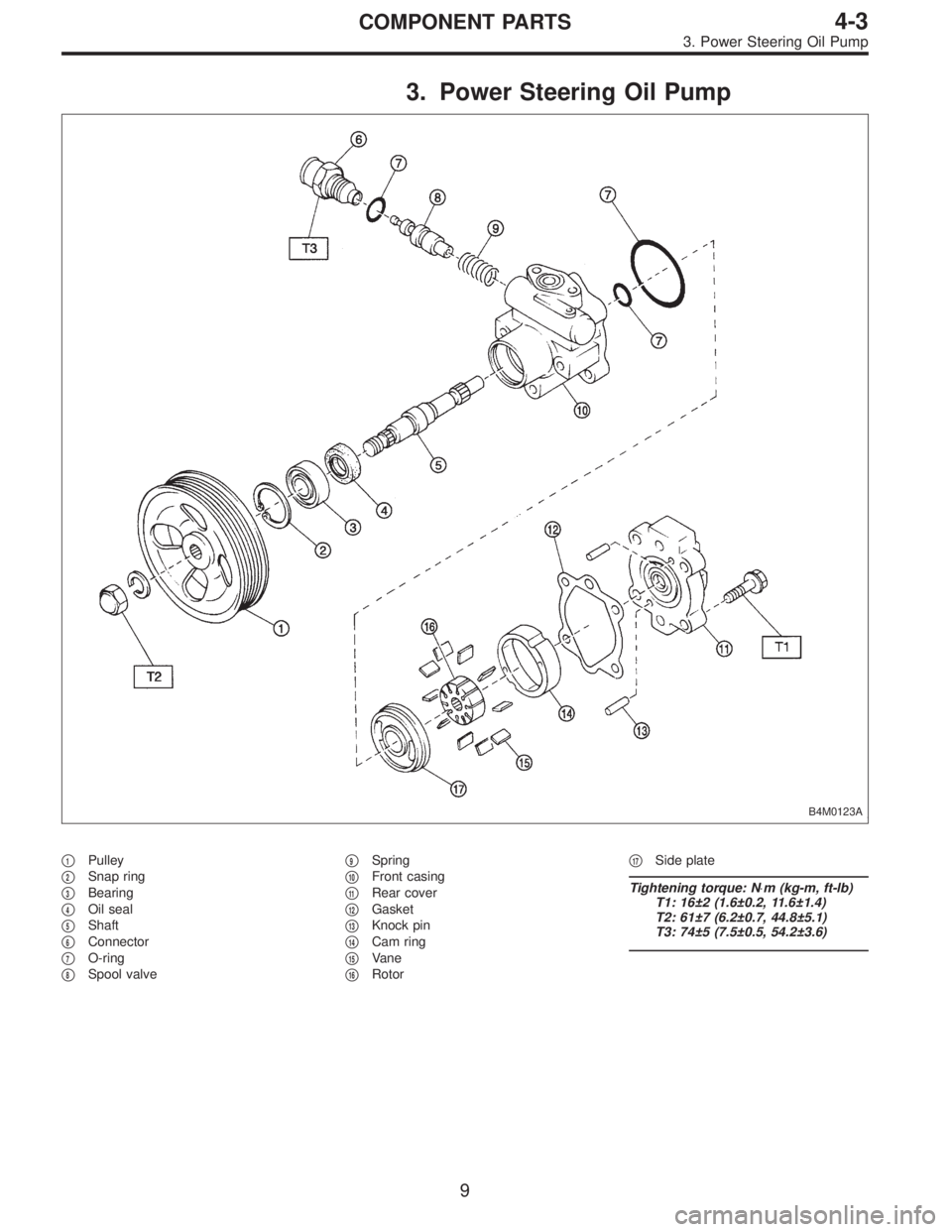
3. Power Steering Oil Pump
B4M0123A
�1Pulley
�
2Snap ring
�
3Bearing
�
4Oil seal
�
5Shaft
�
6Connector
�
7O-ring
�
8Spool valve�
9Spring
�
10Front casing
�
11Rear cover
�
12Gasket
�
13Knock pin
�
14Cam ring
�
15Vane
�
16Rotor�
17Side plate
Tightening torque: N⋅m (kg-m, ft-lb)
T1: 16±2 (1.6±0.2, 11.6±1.4)
T2: 61±7 (6.2±0.7, 44.8±5.1)
T3: 74±5 (7.5±0.5, 54.2±3.6)
9
4-3COMPONENT PARTS
3. Power Steering Oil Pump
Page 1122 of 2890
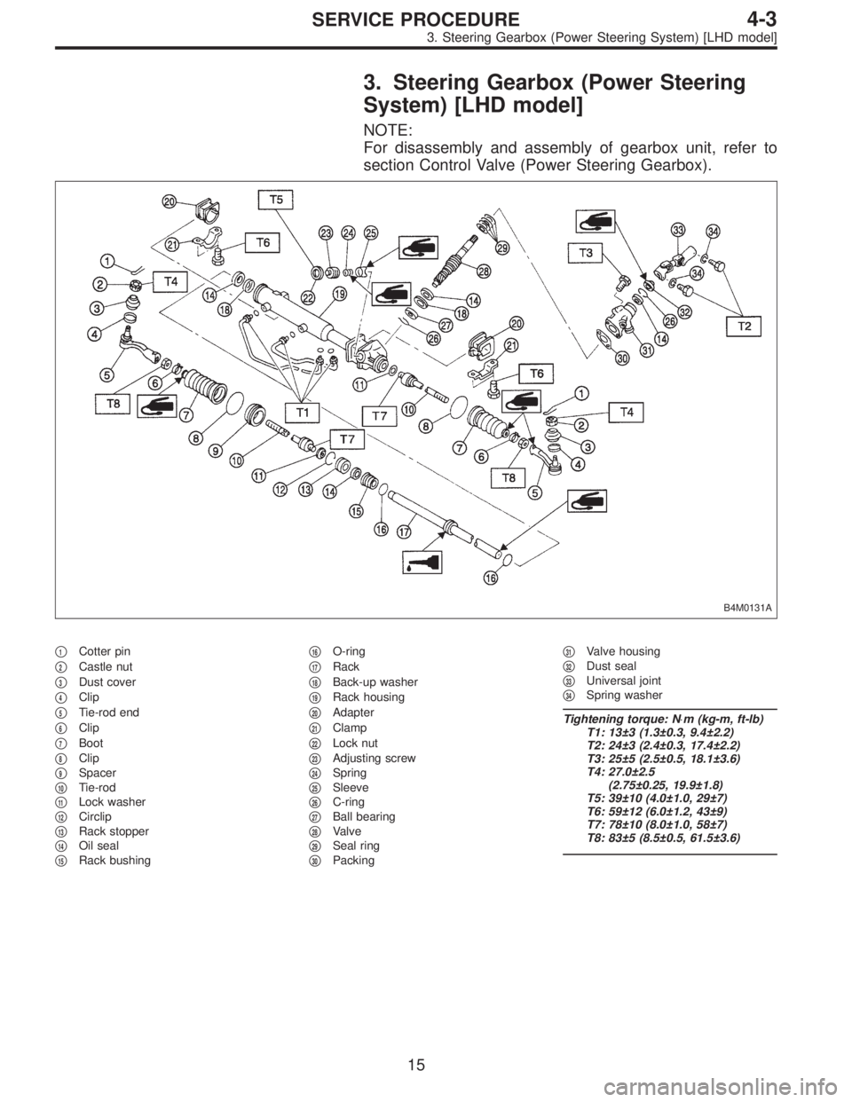
3. Steering Gearbox (Power Steering
System) [LHD model]
NOTE:
For disassembly and assembly of gearbox unit, refer to
section Control Valve (Power Steering Gearbox).
B4M0131A
�1Cotter pin
�
2Castle nut
�
3Dust cover
�
4Clip
�
5Tie-rod end
�
6Clip
�
7Boot
�
8Clip
�
9Spacer
�
10Tie-rod
�
11Lock washer
�
12Circlip
�
13Rack stopper
�
14Oil seal
�
15Rack bushing�
16O-ring
�
17Rack
�
18Back-up washer
�
19Rack housing
�
20Adapter
�
21Clamp
�
22Lock nut
�
23Adjusting screw
�
24Spring
�
25Sleeve
�
26C-ring
�
27Ball bearing
�
28Valve
�
29Seal ring
�
30Packing�
31Valve housing
�
32Dust seal
�
33Universal joint
�
34Spring washer
Tightening torque: N⋅m (kg-m, ft-lb)
T1: 13±3 (1.3±0.3, 9.4±2.2)
T2: 24±3 (2.4±0.3, 17.4±2.2)
T3: 25±5 (2.5±0.5, 18.1±3.6)
T4: 27.0±2.5
(2.75±0.25, 19.9±1.8)
T5: 39±10 (4.0±1.0, 29±7)
T6: 59±12 (6.0±1.2, 43±9)
T7: 78±10 (8.0±1.0, 58±7)
T8: 83±5 (8.5±0.5, 61.5±3.6)
15
4-3SERVICE PROCEDURE
3. Steering Gearbox (Power Steering System) [LHD model]
Page 1123 of 2890
A: REMOVAL
1) Disconnect battery minus terminal.
2) Loosen front wheel nut.
3) Lift vehicle and remove front wheels.
4) Remove front exhaust pipe assembly.
WARNING:
Be careful, exhaust pipe is hot.
G4M0097
5) Using a puller, remove tie-rod end from knuckle arm
after pulling off cotter pin and removing castle nut.
G4M0098
6) Remove jack-up plate and front stabilizer.
G4M0099
7) Remove one pipe joint at the center of gearbox, and
connect vinyl hose to pipe and joint. Discharge fluid by
turning steering wheel fully clockwise and counterclock-
wise. Discharge fluid similarly from the other pipe.
G4M0086
8) Remove lower side bolt of universal joint, then remove
upper side bolt and lift the joint upward.
NOTE:
Place a mark on the joint and mating serration so that they
can be re-installed at the original position.
16
4-3SERVICE PROCEDURE
3. Steering Gearbox (Power Steering System) [LHD model]
Page 1124 of 2890
G4M0101
9) Disconnect pipes C and D from pipe of gearbox.
CAUTION:
Be careful not to damage these pipes.
NOTE:
Disconnect upper pipe D first, and lower pipe C second.
G4M0102
10) Remove clamp bolts securing gearbox to
crossmember, and remove gearbox.
B4M0132A
B: DISASSEMBLY
1) Disconnect four pipes from gearbox.
2) Secure gearbox removed from vehicle in vice using ST.
ST 926200000 STAND
CAUTION:
Secure the gearbox in a vice using the ST as shown.
Do not attempt to secure it without this ST.
3) Remove tie-rod end and lock nut from gearbox.
G4M0104
4) Remove small clip from boot using pliers, and move
boot to tie-rod end side.
G4M0105
5) Remove boot together with large clips.
17
4-3SERVICE PROCEDURE
3. Steering Gearbox (Power Steering System) [LHD model]
Page 1125 of 2890
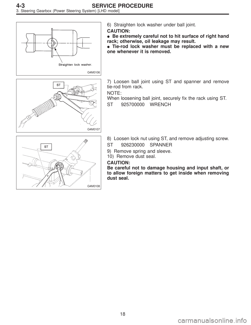
G4M0106
6) Straighten lock washer under ball joint.
CAUTION:
�Be extremely careful not to hit surface of right hand
rack; otherwise, oil leakage may result.
�Tie-rod lock washer must be replaced with a new
one whenever it is removed.
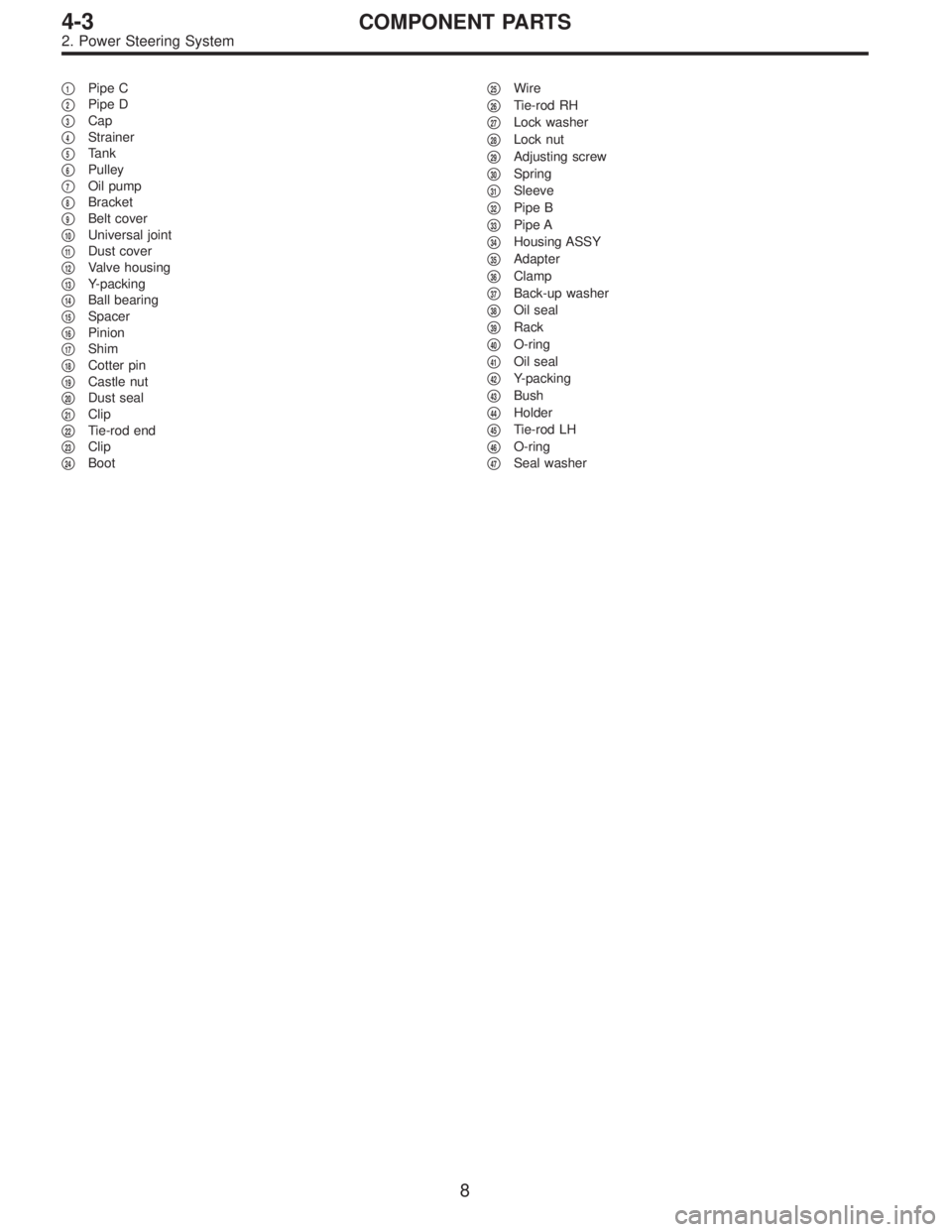
G4M0107
7) Loosen ball joint using ST and spanner and remove
tie-rod from rack.
NOTE:
When loosening ball joint, securely fix the rack using ST.
ST 925700000 WRENCH
G4M0108
8) Loosen lock nut using ST, and remove adjusting screw.
ST 926230000 SPANNER
9) Remove spring and sleeve.
10) Remove dust seal.
CAUTION:
Be careful not to damage housing and input shaft, or
to allow foreign matters to get inside when removing
dust seal.
18
4-3SERVICE PROCEDURE
3. Steering Gearbox (Power Steering System) [LHD model]
Page 1126 of 2890
 Clean all disassembled parts, and check for wear,
damage, or any other faults, then repair or replace as nec-
essary.
2) When disassembling, check inside of gearbox for water.
If any")
C: INSPECTION
1) Clean all disassembled parts, and check for wear,
damage, or any other faults, then repair or replace as nec-
essary.
2) When disassembling, check inside of gearbox for water.
If any water is found, carefully check boot for damage,
input shaft dust seal, adjusting screw and boot clips for
poor sealing. If faulty, replace with new parts.
No. Parts Inspection Corrective action
1 Input shaft(1) Bend of input shaft
(2) Damage on serrationIf bend or damage is excessive, replace
entire gearbox.
2 Dust seal(1) Crack or damage
(2) WearIf outer wall slips, lip is worn out or
damage is found, replace it with new one.
3 Rack and pinion Poor mating of rack with pinion(1) Adjust backlash properly.
By measuring turning torque of
gearbox and sliding resistance of rack,
check if rack and pinion engage
uniformly and smoothly with each
other.
(Refer to“Service limit”.)
(2) Keeping rack pulled out all the way so
that all teeth emerge, check teeth for
damage.
Even if abnormality is found in either
(1) or (2), replace entire gearbox.
4 Gearbox unit(1) Bend of rack shaft
(2) Bend of cylinder portion
(3) Crack or damage on cast iron portionReplace gearbox with new one.
(4) Wear or damage on rack bushIf free play of rack shaft in radial direction
is out of the specified range, replace
gearbox with new one. (Refer to“Service
limit”.)
(5) Wear on input shaft bearingIf free plays of input shaft in radial and
axial directions are out of the specified
ranges, replace gearbox with new one.
(Refer to“Service limit”.)
5 Boot Crack, damage or deterioration Replace.
6 Tie-rod(1) Looseness of ball joint
(2) Bend of tie-rodReplace.
7 Tie-rod end Damage or deterioration on dust seal Replace.
8 Adjusting screw spring Deterioration Replace.
9 Boot clip Deterioration Replace.
10 Sleeve Damage Replace.
11 Pipes(1) Damage to flared surface
(2) Damage to flare nut
(3) Damage to pipe
(4) Damage to O-ringReplace.
19
4-3SERVICE PROCEDURE
3. Steering Gearbox (Power Steering System) [LHD model]

T1: 7.4±2.0 (0.75±0.2, 5.4±1.4)
T2: 8±2 (0.8±0.2, 5.8±1.4)
T3: 13±3 (1.3±0.3, 9.4±2.2)
T4: 15±5 (1.5±0.5, 10.8±3.6)
T5: 15.7±2")
 Disconnect battery minus terminal.
2) Loosen front wheel nut.
3) Lift vehicle and remove front wheels.
4) Remove front exhaust pipe assembly.
WARNING:
Be careful, exhaust pipe is hot.
G4")
 Disconnect pipes C and D from pipe of gearbox.
CAUTION:
Be careful not to damage these pipes.
NOTE:
Disconnect upper pipe D first, and lower pipe C second.
G4M0102
10) Remove clamp bolts se")