Page 733 of 2890

B: INSTALLATION
1. Install engine to transmission.
2. Tighten bolts which hold upper side of transmission to engine.
3. Remove lifting device and wire rope.
4. Remove garage jack.
5. Install pitching stopper.
AT model
6. Install torque converter onto drive plate.
7. Install canister and bracket.
8. Install power steering pump on bracket.
9. Tighten nuts which hold lower side of transmission to engine.
10. Tighten nuts which install front cushion rubber onto cross-
member.
11. Install front exhaust pipe and center exhaust pipe.
12. Connect hoses, connectors and cables.
13. Install air intake system.
�Air intake duct
�Air cleaner element and upper cover.
With A/C
14. Install A/C pressure hoses.
15. Install cooling system.
16. Install battery onto the vehicle, and connect cables.
17. Fill coolant.
18. Check ATF level, and connect if necessary. [AT]
19. Correct power steering oil, and bleed air.
20. Remove front hood stay, and close front hood.
21. Take off the vehicle from lift arms.
�
�
�
�
�
�
�
�
�
�
�
�
20
2-11SERVICE PROCEDURE
2. Engine
Page 735 of 2890
G2M0302
5) Install pitching stopper.
Tightening torque:
T1: 49±5 N⋅m (5.0±0.5 kg-m, 36.2±3.6 ft-lb)
T2: 57±10 N⋅m (5.8±1.0 kg-m, 42±7 ft-lb)
G2M0294
6) Install torque converter onto drive plate. (AT model)
(1) Tighten bolts which hold torque converter to drive
plate.
(2) Tighten other bolts while rotating the engine by
using ST.
ST 499977000 CRANK PULLEY WRENCH
CAUTION:
Be careful not to drop bolts into torque converter
housing.
Tightening torque:
25±2 N⋅m (2.5±0.2 kg-m, 18.1±1.4 ft-lb)
(3) Clog plug onto service hole.
G2M0272
7) Install canister and bracket.
B2M0334
8) Install power steering pump on bracket.
(1) Install power steering pump on bracket, and tighten
bolts.
Tightening torque:
39±10 N⋅m (4.0±1.0 kg-m, 29±7 ft-lb)
22
2-11SERVICE PROCEDURE
2. Engine
Page 736 of 2890
B2M0340
(2) Install power steering pipe bracket on right side
intake manifold, and install spark plug codes.
G2M0286
(3) Install front side V-belt, and adjust it.
G2M0292
9) Tighten nuts which hold lower side of transmission to
engine.
Tightening torque:
50±4 N⋅m (5.1±0.4 kg-m, 36.9±2.9 ft-lb)
G2M0303
10) Tighten nuts which install front cushion rubber onto
crossmember.
Tightening torque:
69±15 N⋅m (7.0±1.5 kg-m, 51±11 ft-lb)
CAUTION:
Be sure to tighten front cushion rubber mounting bolts
in the innermost elliptical hole in the front crossmem-
ber.
23
2-11SERVICE PROCEDURE
2. Engine
Page 1029 of 2890
 Disconnect ground cable from battery.
2) Loosen front wheel nuts.
3) Lift-up vehicle, and remove front tires and wheels.
4) Remove both stabilizer and jack-u")
G4M0520
6. Front Crossmember
A: REMOVAL
1) Disconnect ground cable from battery.
2) Loosen front wheel nuts.
3) Lift-up vehicle, and remove front tires and wheels.
4) Remove both stabilizer and jack-up plate.
5) Disconnect tie-rod end from housing.
6) Remove front exhaust pipe.
G4M0521
7) Remove front transverse link from front crossmember
and body.
8) Remove nuts attaching engine mount cushion rubber to
crossmember.
9) Remove self-locking nuts connecting steering U/J and
pinion shaft.
10) Lift engine by approx. 10 mm (0.39 in) by using chain
block.
11) Support crossmember with a jack, remove nuts secur-
ing crossmember to body and lower crossmember gradu-
ally along with steering gearbox.
CAUTION:
When removing crossmember downward, be careful
that tie-rod end does not interfere with DOJ boot.
B: INSTALLATION
1) Installation is in the reverse order of removal proce-
dures.
CAUTION:
Always tighten rubber bushing when wheels are in full
contact with the ground and vehicle is at curb weight
condition.
Tightening torque:
Transverse link bushing to crossmember:
98±15 N⋅m (10.0±1.5 kg-m, 72±11 ft-lb)
Stabilizer to bushing:
25±4 N⋅m (2.5±0.4 kg-m, 18.1±2.9 ft-lb)
Tie-rod end to housing:
27.0±2.5 N⋅m (2.75±0.25 kg-m, 19.9±1.8 ft-lb)
Front cushion rubber to crossmember:
69±15 N⋅m (7.0±1.5 kg-m, 51±11 ft-lb)
Universal joint to pinion shaft:
24±3 N⋅m (2.4±0.3 kg-m, 17.4±2.2 ft-lb)
Crossmember to body:
98±15 N⋅m (10.0±1.5 kg-m, 72±11 ft-lb)
2) Purge air from power steering system.
NOTE:
Check wheel alignment and adjust if necessary.
28
4-1SERVICE PROCEDURE
6. Front Crossmember
Page 1108 of 2890
 5.3 (17.4) 5.6 (18.4)
Steering angle (Inside-Outside) 37.6°—32.6°34.4°—30.2°
S")
1. Steering System
A: SPECIFICATIONS
Except OUTBACK model OUTBACK model
Whole systemMinimum turning radius m (ft) 5.3 (17.4) 5.6 (18.4)
Steering angle (Inside-Outside) 37.6°—32.6°34.4°—30.2°
Steering wheel diameter mm (in) 385 (15.16)
Overall gear ratio (Turns, lock to lock) 16.5 (3.2) 19 (3.4)
GearboxType Rack and pinion, Integral
Backlash 0 (Automatically adjustable)
Valve (Power steering system) Rotary valve
Pump
(Power steering system)Type Vane pump
Oil tank Installed on pump
Output cm
3(cu in)/rev. 7.2 (0.439)
Relief pressure kPa (kg/cm
2, psi) 7,355 (75, 1,067)
Hydraulic fluid controlDropping in response to increased engine
revolutions
Hydraulic fluid�(US qt, Imp qt)1,000 rpm: 7 (7.4, 6.2)
3,000 rpm: 5 (5.3, 4.4)
Range of revolution rpm 500—7,500
Revolving direction Clockwise
Working fluid
(Power steering system)Name ATF DEXRON II, IIE or III
Capacity Oil tank�(US qt, Imp qt)
Total0.35 (0.4, 0.3)
0.7 (0.7, 0.6)
2
4-3SPECIFICATIONS AND SERVICE DATA
1. Steering System
Page 1109 of 2890
 17 (0.67)
Turning angleInner tire & wheel 37.6°34.4°
Outer tire & wheel 32.6°30.2°
Steering shaftClearance betwe")
B: SERVICE DATA
Except OUTBACK model OUTBACK model
Steering wheel Free play mm (in) 17 (0.67)
Turning angleInner tire & wheel 37.6°34.4°
Outer tire & wheel 32.6°30.2°
Steering shaftClearance between steering
wheel and column cover
mm (in)3.0 (0.118)
Steering gearbox
(Power steering system)Sliding resistance N (kg, lb) 240.3 (24.5, 54.0) or less
Rack shaft play in radial direc-
tion
mm (in)0.15 (0.0059) or less
Right-turn steering Horizontal movement: 0.3 (0.012) or less
Left-turn steering Vertical movement: 0.15 (0.0059) or less
Input shaft play mm (in)
In radial direction 0.18 (0.0071) or less
In axial direction 0.1 (0.004) or less
Turning resistance N (kg, lb)Within 30 mm (1.18 in) from rack center in straight ahead posi-
tion: Less than 11.18 (1.14, 2.51)
Maximum allowable value: 12.7 (1.3, 2.9)
Oil pump
(Power steering system)Pulley shaft mm (in)
Radial play 0.4 (0.016) or less
Axial play 0.9 (0.035) or less
Pulley
Ditch deflection mm (in)
Resistance to rotation
N (kg, lb)1.0 (0.039) or less
9.22 (0.94, 2.07) or less
Regular pressure
kPa (kg/cm
2, psi)981 (10, 142) or less
Relief pressure
kPa (kg/cm
2, psi)7,355 (75, 1,067)
Steering wheel effort
(Power steering system)At standstill with engine
idling on a concrete road
N (kg, lb)31.4 (3.2, 7.1) or less
At standstill with engine
stalled on a concrete road
N (kg, lb)147 (15, 33) or less
C: RECOMMENDED POWER STEERING
FLUID
Recommended power steering fluid Manufacturer
ATF DEXRON II, ATF DEXRON IIE or ATF
DEXRON IIIB.P.
CALTEX
CASTROL
MOBIL
SHELL
TEXACO
3
4-3SPECIFICATIONS AND SERVICE DATA
1. Steering System
Page 1111 of 2890
2. Power Steering System
1. LHD MODEL
B4M0767A
Tightening torque: N⋅m (kg-m, ft-lb)
T1: 5.4±1.5 (0.55±0.15, 4.0±1.1)
T2: 7.4±2.0 (0.75±0.20, 5.4±1.4)
T3: 8±2 (0.8±0.2, 5.8±1.4)
T4: 13±3 (1.3±0.3, 9.4±2.2)
T5: 15±5 (1.5±0.5, 10.8±3.6)
T6: 15.7±2.4 (1.60±0.24, 11.58±1.77)
T7: 18.1±2.5 (1.85±0.25, 13.35±1.84)
T8: 20.1±2.5 (2.05±0.25, 14.8±1.8)
T9: 22±2 (2.2±0.2, 15.9±1.4)T10: 24±3 (2.4±0.3, 17.4±2.2)
T11: 24.5±2.0 (2.50±0.2, 18.07±1.48)
T12: 25±5 (2.5±0.5, 18.1±3.6)
T13: 27.0±2.5 (2.75±0.25, 19.92±1.84)
T14: 59±12 (6.0±1.2, 43±9)
T15: 60.8±6.9 (6.2±0.7, 44.8±5.1)
T16: 78±10 (8.0±1.0, 58±7)
T17: 83±5 (8.5±0.5, 61.5±3.6)
T18: 6.35±1.0 (0.65±0.1, 4.7±0.7)
5
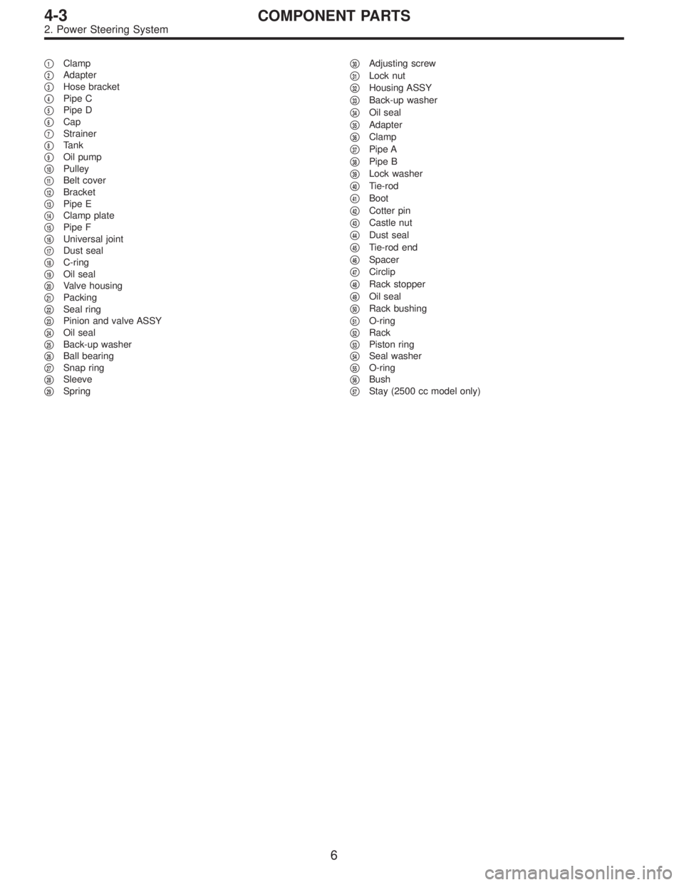
4-3COMPONENT PARTS
2. Power Steering System
Page 1112 of 2890
�1Clamp
�
2Adapter
�
3Hose bracket
�
4Pipe C
�
5Pipe D
�
6Cap
�
7Strainer
�
8Tank
�
9Oil pump
�
10Pulley
�
11Belt cover
�
12Bracket
�
13Pipe E
�
14Clamp plate
�
15Pipe F
�
16Universal joint
�
17Dust seal
�
18C-ring
�
19Oil seal
�
20Valve housing
�
21Packing
�
22Seal ring
�
23Pinion and valve ASSY
�
24Oil seal
�
25Back-up washer
�
26Ball bearing
�
27Snap ring
�
28Sleeve
�
29Spring�
30Adjusting screw
�
31Lock nut
�
32Housing ASSY
�
33Back-up washer
�
34Oil seal
�
35Adapter
�
36Clamp
�
37Pipe A
�
38Pipe B
�
39Lock washer
�
40Tie-rod
�
41Boot
�
42Cotter pin
�
43Castle nut
�
44Dust seal
�
45Tie-rod end
�
46Spacer
�
47Circlip
�
48Rack stopper
�
49Oil seal
�
50Rack bushing
�
51O-ring
�
52Rack
�
53Piston ring
�
54Seal washer
�
55O-ring
�
56Bush
�
57Stay (2500 cc model only)
6
4-3COMPONENT PARTS
2. Power Steering System
 Install pitching stopper.
Tightening torque:
T1: 49±5 N⋅m (5.0±0.5 kg-m, 36.2±3.6 ft-lb)
T2: 57±10 N⋅m (5.8±1.0 kg-m, 42±7 ft-lb)
G2M0294
6) Install torque converter onto drive pl")
![SUBARU LEGACY 1996 Service Repair Manual B2M0340
(2) Install power steering pipe bracket on right side
intake manifold, and install spark plug codes.
G2M0286
(3) Install front side V-belt, and adjust it.
<Ref. to 1-5 [01A0].>
G2M0292
9) Tigh](/manual-img/17/57433/w960_57433-735.png "SUBARU LEGACY 1996 Service Repair Manual B2M0340
(2) Install power steering pipe bracket on right side
intake manifold, and install spark plug codes.
G2M0286
(3) Install front side V-belt, and adjust it.
<Ref. to 1-5 [01A0].>
G2M0292
9) Tigh")

T1: 5.4±1.5 (0.55±0.15, 4.0±1.1)
T2: 7.4±2.0 (0.75±0.20, 5.4±1.4)
T3: 8±2 (0.8±0.2, 5.8±1.4)
T4: 13±3 (1")