Page 2106 of 2890
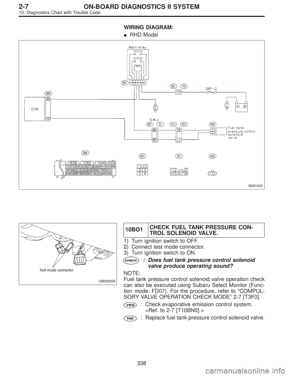
WIRING DIAGRAM:
�RHD Model
B2M1020
OBD0005B
10BO1CHECK FUEL TANK PRESSURE CON-
TROL SOLENOID VALVE.
1) Turn ignition switch to OFF.
2) Connect test mode connector.
3) Turn ignition switch to ON.
: Does fuel tank pressure control solenoid
valve produce operating sound?
NOTE:
Fuel tank pressure control solenoid valve operation check
can also be executed using Subaru Select Monitor (Func-
tion mode: FD07). For the procedure, refer to“COMPUL-
SORY VALVE OPERATION CHECK MODE”2-7 [T3F0].
: Check evaporative emission control system.
: Replace fuel tank pressure control solenoid valve.
338
2-7ON-BOARD DIAGNOSTICS II SYSTEM
10. Diagnostics Chart with Trouble Code
Page 2108 of 2890
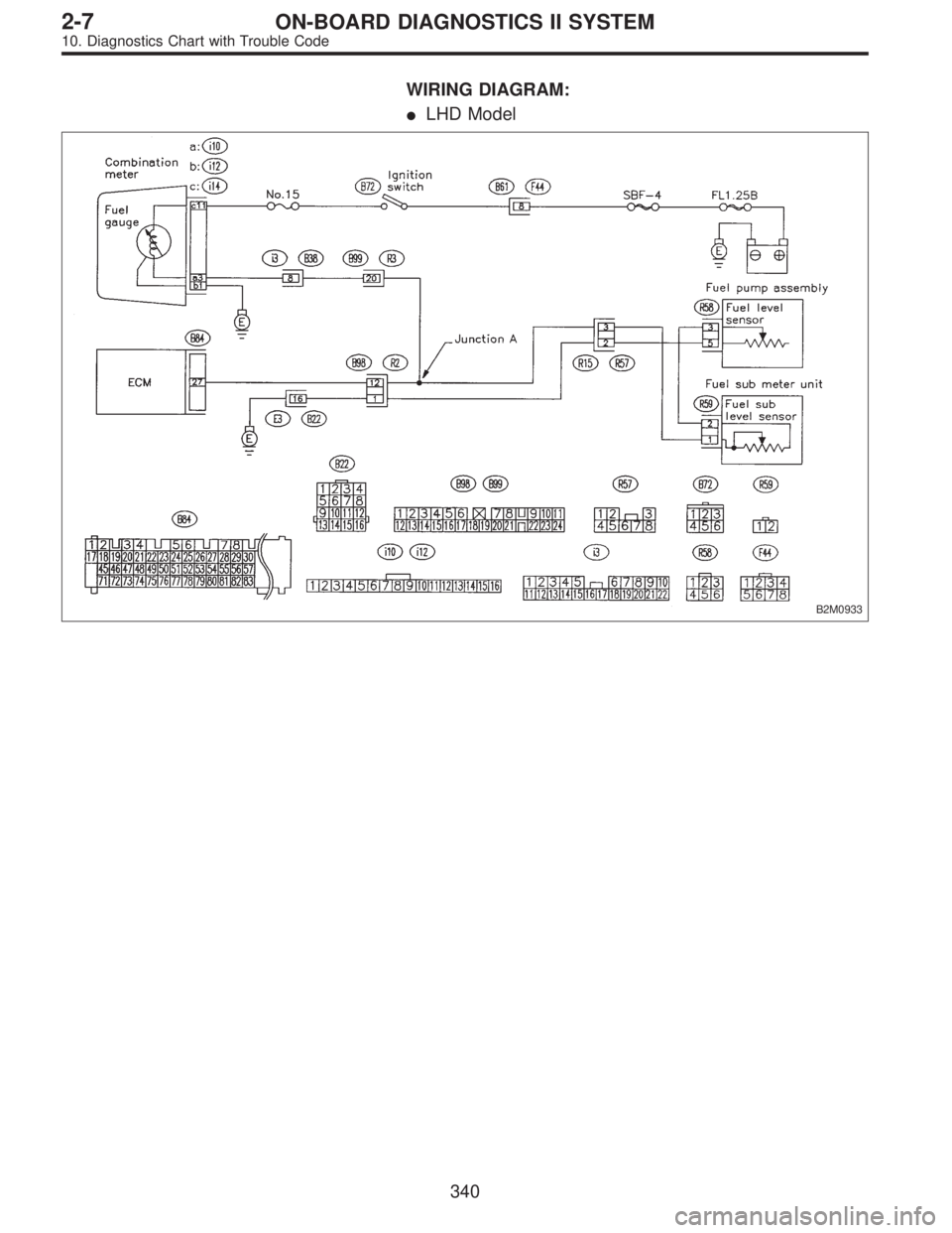
WIRING DIAGRAM:
�LHD Model
B2M0933
340
2-7ON-BOARD DIAGNOSTICS II SYSTEM
10. Diagnostics Chart with Trouble Code
Page 2109 of 2890
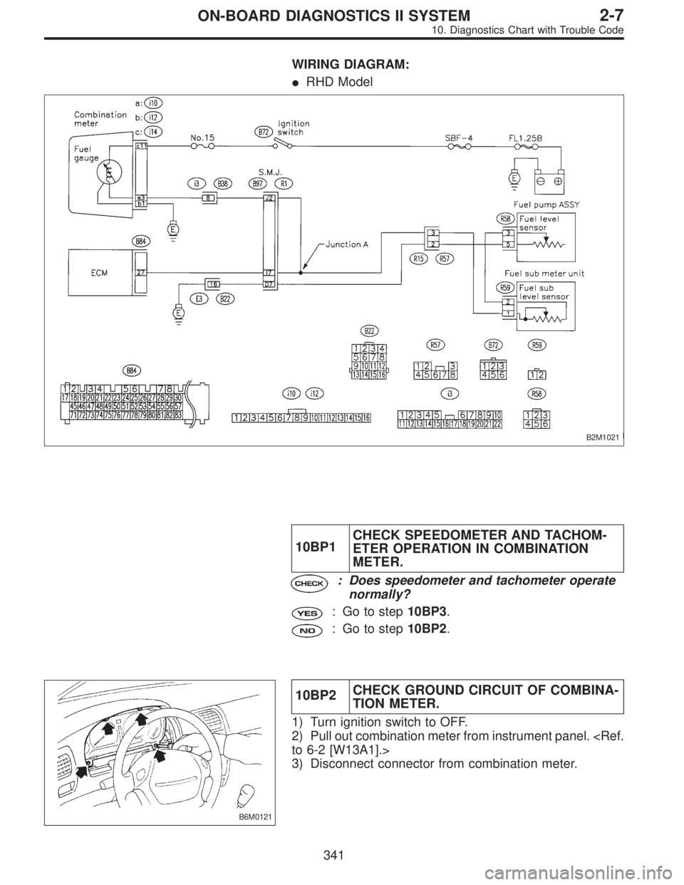
WIRING DIAGRAM:
�RHD Model
B2M1021
10BP1CHECK SPEEDOMETER AND TACHOM-
ETER OPERATION IN COMBINATION
METER.
: Does speedometer and tachometer operate
normally?
: Go to step10BP3.
: Go to step10BP2.
B6M0121
10BP2CHECK GROUND CIRCUIT OF COMBINA-
TION METER.
1) Turn ignition switch to OFF.
2) Pull out combination meter from instrument panel.
to 6-2 [W13A1].>
3) Disconnect connector from combination meter.
341
2-7ON-BOARD DIAGNOSTICS II SYSTEM
10. Diagnostics Chart with Trouble Code
Page 2120 of 2890
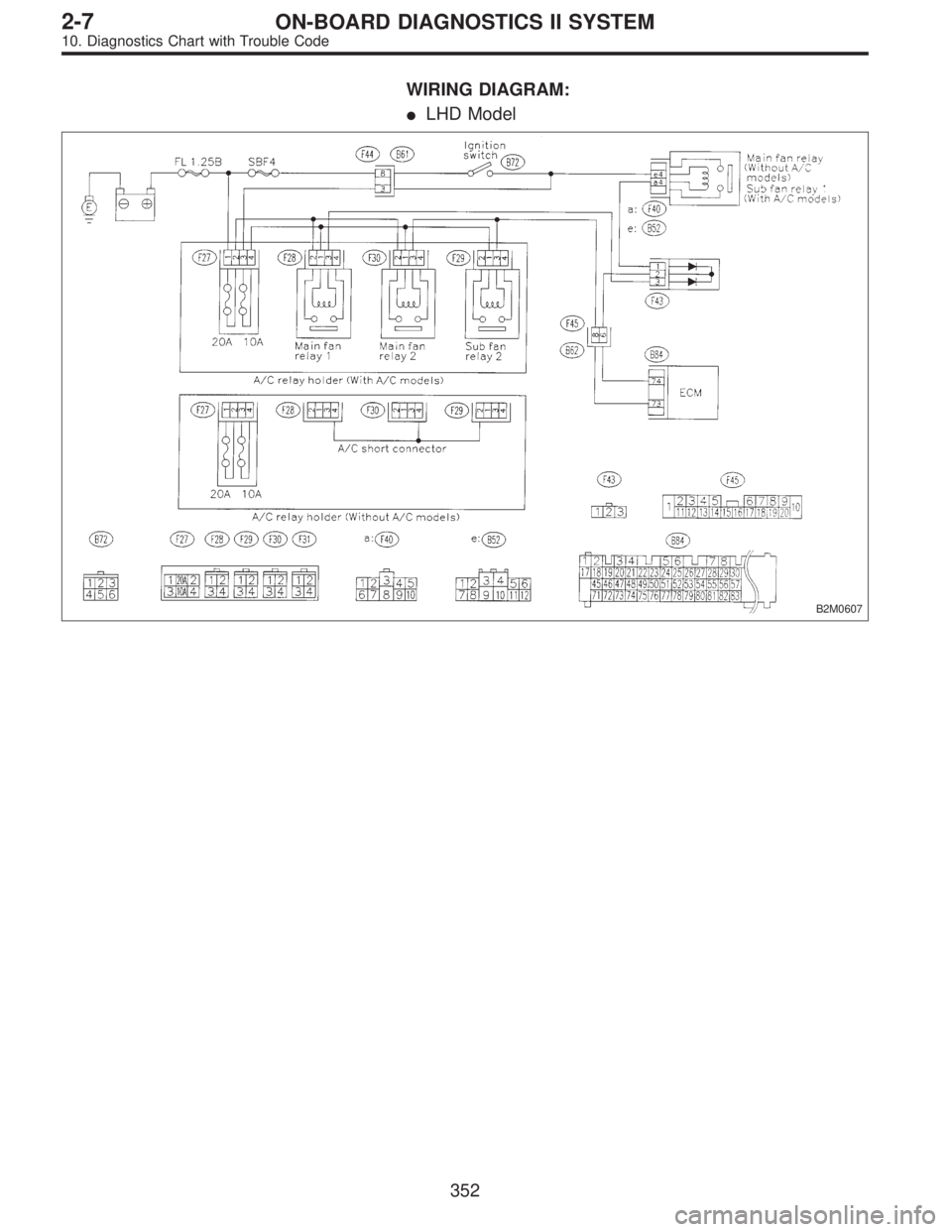
WIRING DIAGRAM:
�LHD Model
B2M0607
352
2-7ON-BOARD DIAGNOSTICS II SYSTEM
10. Diagnostics Chart with Trouble Code
Page 2121 of 2890
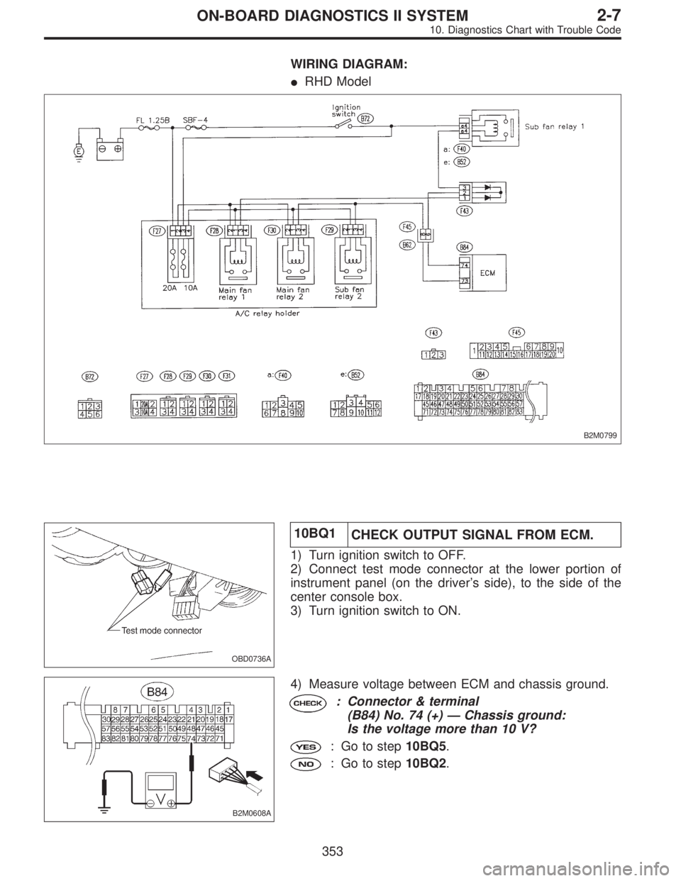
WIRING DIAGRAM:
�RHD Model
B2M0799
OBD0736A
10BQ1
CHECK OUTPUT SIGNAL FROM ECM.
1) Turn ignition switch to OFF.
2) Connect test mode connector at the lower portion of
instrument panel (on the driver’s side), to the side of the
center console box.
3) Turn ignition switch to ON.
B2M0608A
4) Measure voltage between ECM and chassis ground.
: Connector & terminal
(B84) No. 74 (+)—Chassis ground:
Is the voltage more than 10 V?
: Go to step10BQ5.
: Go to step10BQ2.
353
2-7ON-BOARD DIAGNOSTICS II SYSTEM
10. Diagnostics Chart with Trouble Code
Page 2127 of 2890
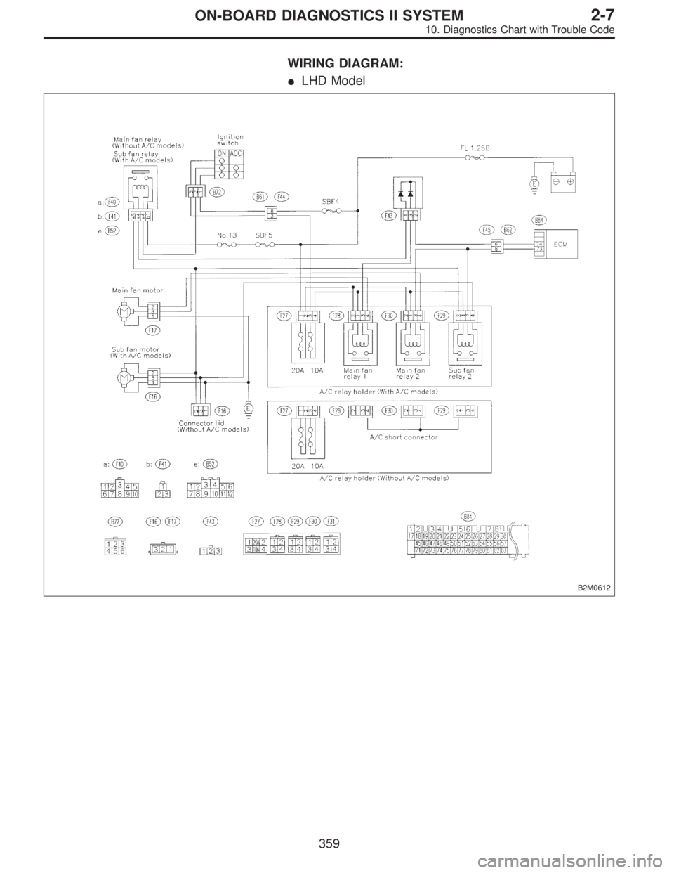
WIRING DIAGRAM:
�LHD Model
B2M0612
359
2-7ON-BOARD DIAGNOSTICS II SYSTEM
10. Diagnostics Chart with Trouble Code
Page 2128 of 2890
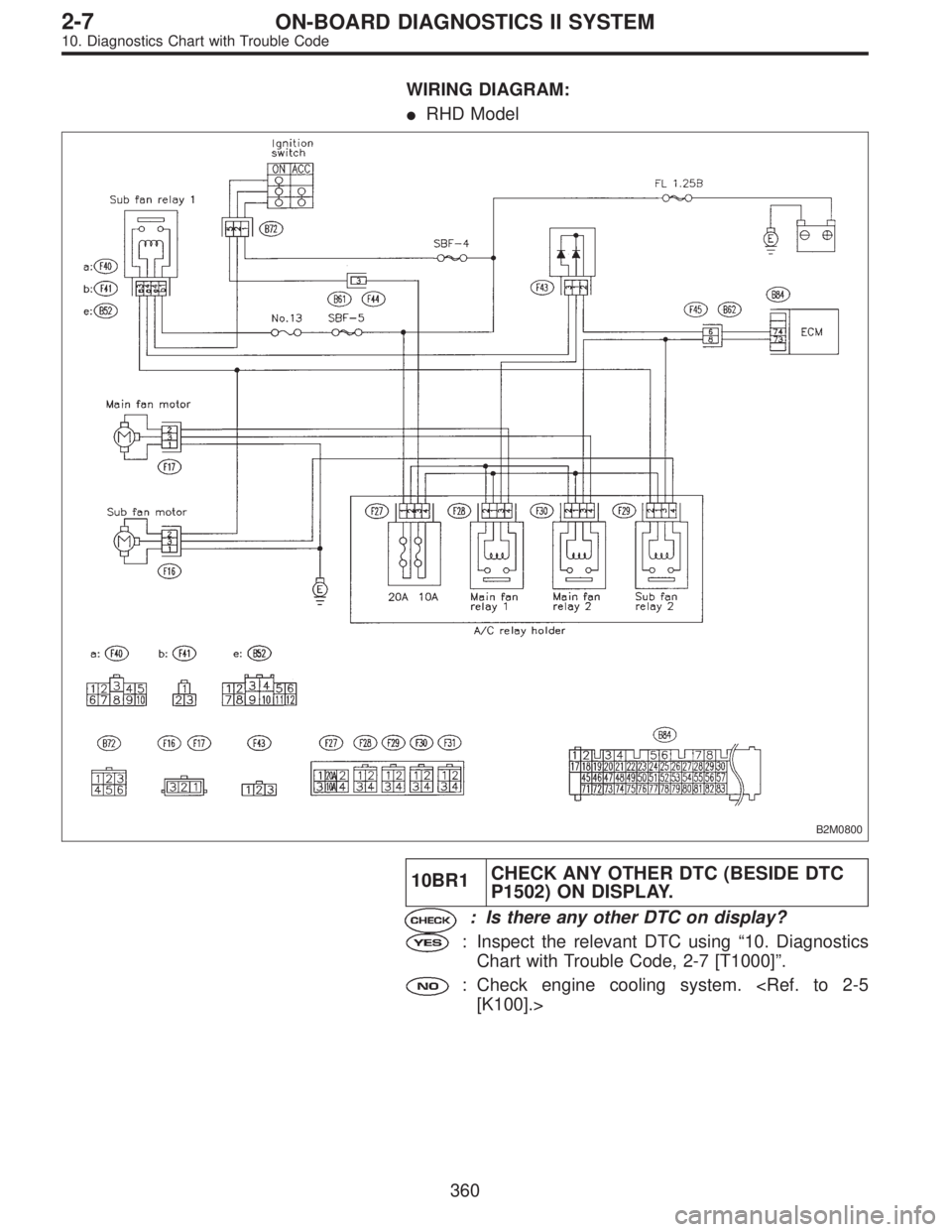
WIRING DIAGRAM:
�RHD Model
B2M0800
10BR1CHECK ANY OTHER DTC (BESIDE DTC
P1502) ON DISPLAY.
: Is there any other DTC on display?
: Inspect the relevant DTC using“10. Diagnostics
Chart with Trouble Code, 2-7 [T1000]”.
: Check engine cooling system.
[K100].>
360
2-7ON-BOARD DIAGNOSTICS II SYSTEM
10. Diagnostics Chart with Trouble Code
Page 2129 of 2890
OBD0501
BS: DTC P1700
—THROTTLE POSITION SENSOR CIRCUIT
MALFUNCTION FOR AUTOMATIC
TRANSMISSION (ATTH)—
DTC DETECTING CONDITION:
�Two consecutive trips with fault
TROUBLE SYMPTOM:
�Shift point too high or too low; engine brake not effected
in“3”range; excessive shift shock; excessive tight corner
“braking”
10BS1Check DTC P1700 on display.
Check throttle position sensor circuit.
CAUTION:
After repair or replacement of faulty parts, conduct
CLEAR MEMORY and INSPECTION MODES.
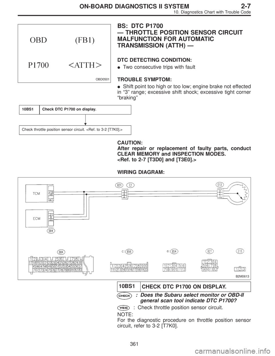
WIRING DIAGRAM:
B2M0613
10BS1
CHECK DTC P1700 ON DISPLAY.
: Does the Subaru select monitor or OBD-II
general scan tool indicate DTC P1700?
: Check throttle position sensor circuit.
NOTE:
For the diagnostic procedure on throttle position sensor
circuit, refer to 3-2 [T7K0].
�
361
2-7ON-BOARD DIAGNOSTICS II SYSTEM
10. Diagnostics Chart with Trouble Code