Page 2025 of 2890
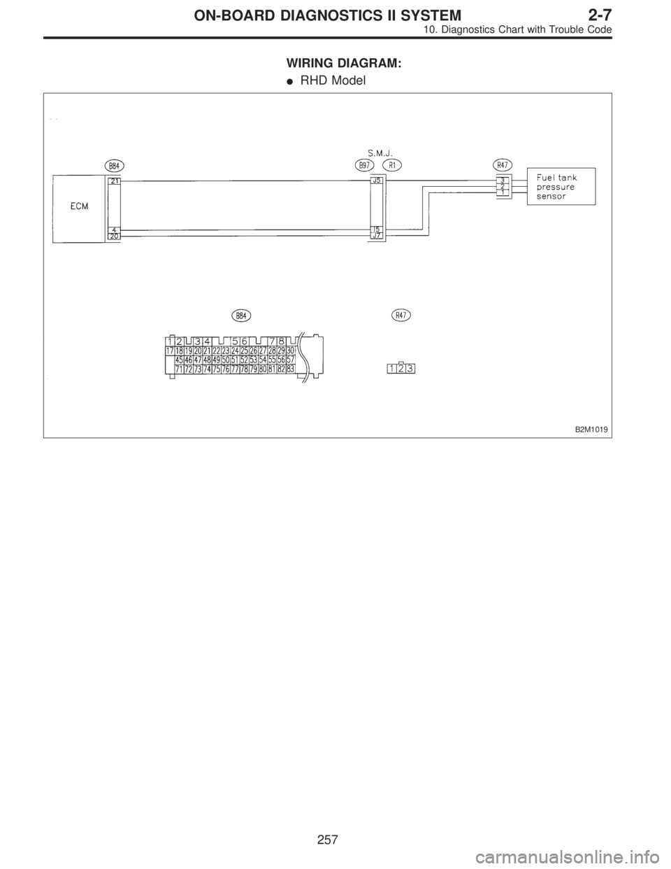
WIRING DIAGRAM:
�RHD Model
B2M1019
257
2-7ON-BOARD DIAGNOSTICS II SYSTEM
10. Diagnostics Chart with Trouble Code
Page 2032 of 2890
H2M1377
AL: DTC P0451
—EVAPORATIVE EMISSION CONTROL
SYSTEM PRESSURE SENSOR
RANGE/PERFORMANCE PROBLEM
(TNKP
—F)—
DTC DETECTING CONDITION:
�Two consecutive trips with fault
10AL1Check pressure/vacuum line.
CAUTION:
After repair or replacement of faulty parts, conduct
CLEAR MEMORY and INSPECTION MODES.
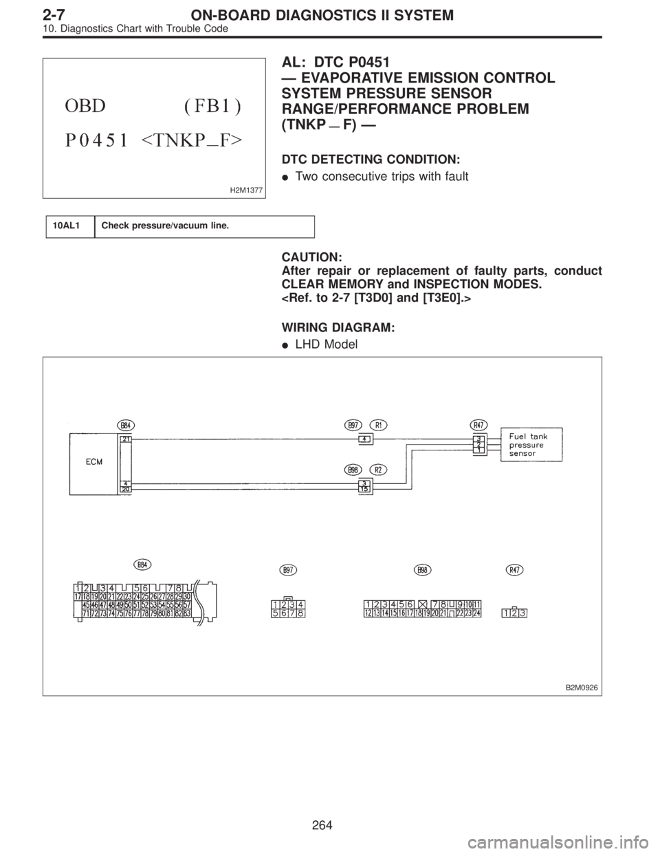
WIRING DIAGRAM:
�LHD Model
B2M0926
264
2-7ON-BOARD DIAGNOSTICS II SYSTEM
10. Diagnostics Chart with Trouble Code
Page 2033 of 2890
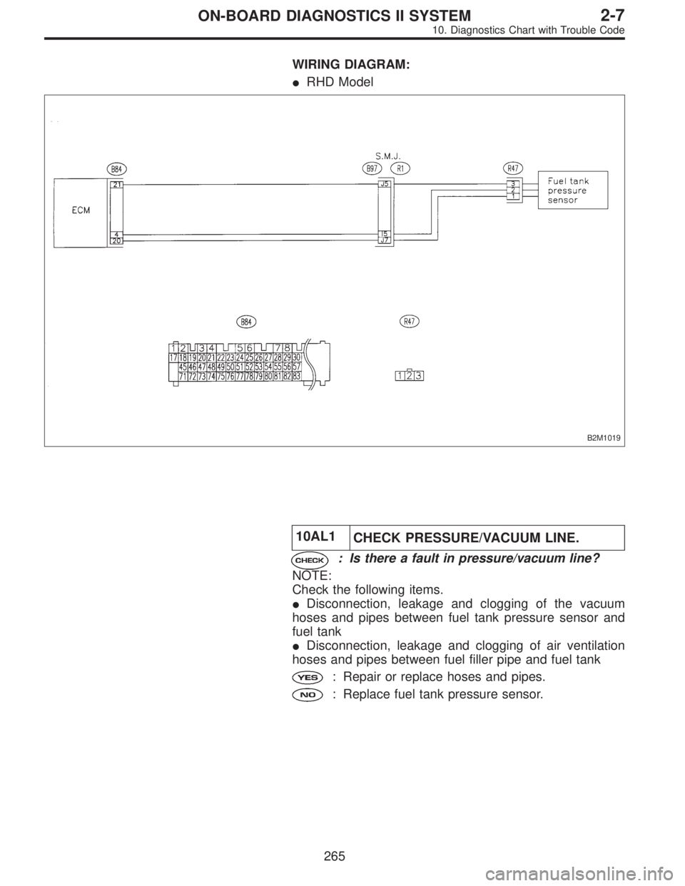
WIRING DIAGRAM:
�RHD Model
B2M1019
10AL1
CHECK PRESSURE/VACUUM LINE.
: Is there a fault in pressure/vacuum line?
NOTE:
Check the following items.
�Disconnection, leakage and clogging of the vacuum
hoses and pipes between fuel tank pressure sensor and
fuel tank
�Disconnection, leakage and clogging of air ventilation
hoses and pipes between fuel filler pipe and fuel tank
: Repair or replace hoses and pipes.
: Replace fuel tank pressure sensor.
265
2-7ON-BOARD DIAGNOSTICS II SYSTEM
10. Diagnostics Chart with Trouble Code
Page 2034 of 2890
OBD0340
AM: DTC P0500
—VEHICLE SPEED SENSOR MALFUNCTION
(VSP)—
DTC DETECTING CONDITION:
�Immediately at fault recognition
10AM1Check speedometer operation in combination
meter.
10AM2Check harness between ECM and combination
meter connector.
10AM3Check harness between ECM and combination
meter connector.
CAUTION:
After repair or replacement of faulty parts, conduct
CLEAR MEMORY and INSPECTION MODES.
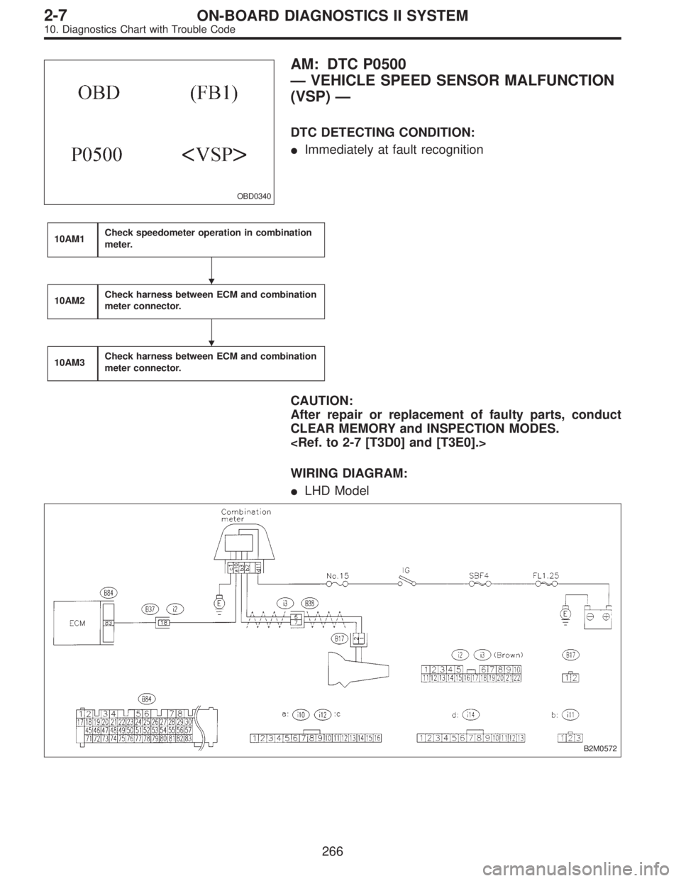
WIRING DIAGRAM:
�LHD Model
B2M0572
�
�
266
2-7ON-BOARD DIAGNOSTICS II SYSTEM
10. Diagnostics Chart with Trouble Code
Page 2035 of 2890
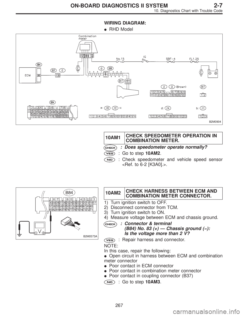
WIRING DIAGRAM:
�RHD Model
B2M0904
10AM1CHECK SPEEDOMETER OPERATION IN
COMBINATION METER.
: Does speedometer operate normally?
: Go to step10AM2.
: Check speedometer and vehicle speed sensor
.
B2M0573A
10AM2CHECK HARNESS BETWEEN ECM AND
COMBINATION METER CONNECTOR.
1) Turn ignition switch to OFF.
2) Disconnect connector from TCM.
3) Turn ignition switch to ON.
4) Measure voltage between ECM and chassis ground.
: Connector & terminal
(B84) No. 83 (+)—Chassis ground (�):
Is the voltage more than 2 V?
: Repair harness and connector.
NOTE:
In this case, repair the following:
�Open circuit in harness between ECM and combination
meter connector
�Poor contact in ECM connector
�Poor contact in combination meter connector
�Poor contact in coupling connector (B37)
: Go to step10AM3.
267
2-7ON-BOARD DIAGNOSTICS II SYSTEM
10. Diagnostics Chart with Trouble Code
Page 2038 of 2890
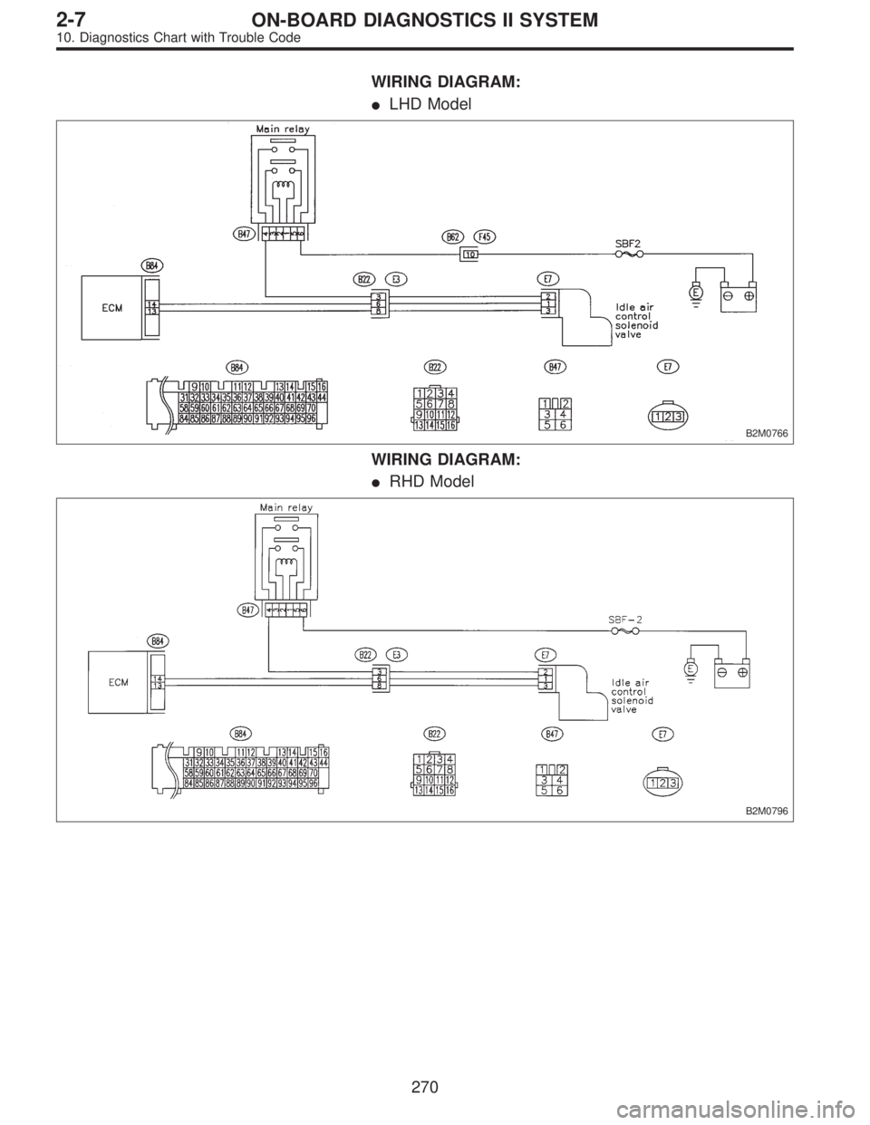
WIRING DIAGRAM:
�LHD Model
B2M0766
WIRING DIAGRAM:
�RHD Model
B2M0796
270
2-7ON-BOARD DIAGNOSTICS II SYSTEM
10. Diagnostics Chart with Trouble Code
Page 2046 of 2890
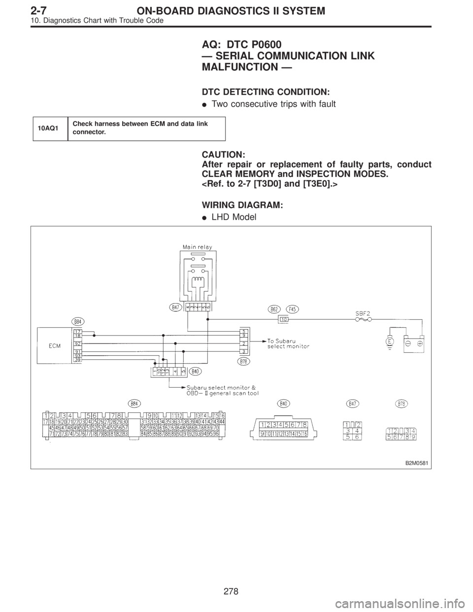
AQ: DTC P0600
—SERIAL COMMUNICATION LINK
MALFUNCTION—
DTC DETECTING CONDITION:
�Two consecutive trips with fault
10AQ1Check harness between ECM and data link
connector.
CAUTION:
After repair or replacement of faulty parts, conduct
CLEAR MEMORY and INSPECTION MODES.
WIRING DIAGRAM:
�LHD Model
B2M0581
278
2-7ON-BOARD DIAGNOSTICS II SYSTEM
10. Diagnostics Chart with Trouble Code
Page 2047 of 2890
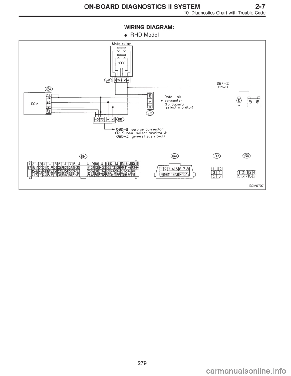
WIRING DIAGRAM:
�RHD Model
B2M0797
279
2-7ON-BOARD DIAGNOSTICS II SYSTEM
10. Diagnostics Chart with Trouble Code