Page 2693 of 2890
![SUBARU LEGACY 1996 Service Repair Manual 1. AIRBAG COMPONENT PARTS APPEARANCE
INSPECTION
1) Conduct on-board diagnostic and call up trouble codes
stored in memory. <Ref. to 5-5b [T4B0].>
2) Select trouble code required to check airbag compo-](/manual-img/17/57433/w960_57433-2692.png "SUBARU LEGACY 1996 Service Repair Manual 1. AIRBAG COMPONENT PARTS APPEARANCE
INSPECTION
1) Conduct on-board diagnostic and call up trouble codes
stored in memory. <Ref. to 5-5b [T4B0].>
2) Select trouble code required to check airbag compo-")
1. AIRBAG COMPONENT PARTS APPEARANCE
INSPECTION
1) Conduct on-board diagnostic and call up trouble codes
stored in memory.
2) Select trouble code required to check airbag compo-
nent parts from those listed in table and reproduce symp-
tom.
Trouble codes Check parts Refer to 5-5b:
04�Airbag module (Passenger)
�Airbag main harness
�Airbag control moduleW3A2
W4A0
W5A0
11�Fuse No. 8
�Airbag main harness
�Airbag control module
�Body harnessT5D3
W4A0
W5A0
—
12�Roll connector
�Airbag module (Driver)
�Airbag main harness
�Airbag control moduleW6A0
W3A1
W4A0
W5A0
13�Airbag module (Driver)
�Roll connector
�Airbag main harness
�Airbag control moduleW3A1
W6A0
W4A0
W5A0
21�Airbag control module W5A0
22�Airbag module (Passenger)
�Airbag main harness
�Airbag control moduleW3A2
W4A0
W5A0
33�Airbag control module W5A0
34�Airbag main harness
�Airbag module (Passenger)
�Airbag control moduleW4A0
W3A2
W5A0
41�Airbag module (Driver)
�Roll connector
�Airbag main harness
�Airbag control moduleW3A1
W6A0
W4A0
W5A0
42�Airbag module (Passenger)
�Airbag main harness
�Airbag control moduleW3A2
W4A0
W5A0
43�Airbag module (Driver)
�Roll connector
�Airbag main harness
�Airbag control moduleW3A1
W6A0
W4A0
W5A0
39
5-5bSUPPLEMENTAL RESTRAINT SYSTEM (ELECTRIC SENSOR TYPE)
5. Diagnostics Chart with Trouble Code
Page 2695 of 2890

Q: WARNING LIGHT INDICATES TROUBLE
CODE, THEN NORMAL CODE.
—FLASHING NORMAL CODE.—
DIAGNOSIS:
�Airbag connector is faulty.
�Fuse No. 16 is blown.
�Airbag main harness is faulty.
�Airbag control module is faulty.
�Body harness is faulty.
1. Airbag connector appearance inspection
2. Airbag connector vibration inspection
3. Showering inspection to body
4. Fuse No. 16, airbag main harness, airbag
control module, body harness appearance
inspection
5. Fuse No. 16, airbag main harness, body
harness vibration inspection
6. Showering inspection to body
7. Warning light illumination check
CAUTION:
Before performing diagnostics on airbag system, turn
ignition switch“OFF”, disconnect battery ground
cable, and then wait at least 20 seconds.
1. AIRBAG CONNECTOR APPEARANCE INSPECTION
Conduct appearance inspection on airbag connectors
(AB2) through (AB8).
: Is there anything unusual about the appear-
ance of connectors (AB2) through (AB8)?
: Replace faulty airbag component parts.
: Go to step2.
NOTE:
Check terminals, case and wiring harnesses for damage.
�
�
�
�
�
�
41
5-5bSUPPLEMENTAL RESTRAINT SYSTEM (ELECTRIC SENSOR TYPE)
5. Diagnostics Chart with Trouble Code
Page 2696 of 2890
![SUBARU LEGACY 1996 Service Repair Manual 2. AIRBAG CONNECTOR VIBRATION INSPECTION
Conduct vibration inspection on airbag connectors (AB2)
through (AB8). <Ref. to 5-5b [T100].>
: Do the connectors (AB2) through (AB8) mal-
function again when](/manual-img/17/57433/w960_57433-2695.png "SUBARU LEGACY 1996 Service Repair Manual 2. AIRBAG CONNECTOR VIBRATION INSPECTION
Conduct vibration inspection on airbag connectors (AB2)
through (AB8). <Ref. to 5-5b [T100].>
: Do the connectors (AB2) through (AB8) mal-
function again when")
2. AIRBAG CONNECTOR VIBRATION INSPECTION
Conduct vibration inspection on airbag connectors (AB2)
through (AB8).
: Do the connectors (AB2) through (AB8) mal-
function again when shaking?
: Replace faulty airbag component parts.
: Go to step3.
NOTE:
Gently shake each airbag connector.
G5M0461
3. SHOWERING INSPECTION TO BODY
Spray water on vehicle body.
CAUTION:
Do not directly spray water on airbag components.
: Does water leak into the passenger com-
partment when showering vehicle?
: Replace faulty airbag component parts.
: Go to step4.
NOTE:
If leaks are noted, also check wiring harnesses as water
may leak along them and wet airbag connectors.
4. FUSE No. 16, AIRBAG MAIN HARNESS, AIRBAG
CONTROL MODULE, BODY HARNESS APPEARANCE
INSPECTION
Conduct appearance inspection on fuse No. 16
5-5b [T5H3].>, airbag main harness
[W4A0].>, airbag control module
and body harness.
: Is there anything unusual about the appear-
ance of fuse No. 16, airbag main harness,
airbag control module or body harness?
: Replace faulty airbag component parts.
: Go to step5.
NOTE:
Also check connectors, terminals, wiring harness and case
for damage.
42
5-5bSUPPLEMENTAL RESTRAINT SYSTEM (ELECTRIC SENSOR TYPE)
5. Diagnostics Chart with Trouble Code
Page 2697 of 2890

5. FUSE No. 16, AIRBAG MAIN HARNESS, BODY
HARNESS VIBRATION INSPECTION
Conduct vibration inspection on fuse No. 16, airbag main
harness and body harness.
CAUTION:
Do not shake or vibrate airbag control module.
: Do fuse No. 16, airbag main harness or
body harness malfunction again when shak-
ing?
: Replace faulty airbag component parts.
: Go to step6.
NOTE:
Gently shake each part.
G5M0461
6. SHOWERING INSPECTION TO BODY
Spray water on vehicle body.
CAUTION:
Do not directly spray water on each part.
: Does water leak into the passenger com-
partment when showering vehicle?
: Replace faulty airbag component parts.
: Go to step7.
NOTE:
If leaks are noted, check wiring harnesses as water may
leak along them and get parts wet.
7. WARNING LIGHT ILLUMINATION CHECK
Turn ignition switch“ON”(engine off) and observe airbag
warning light.
: Does the airbag warning light comes on for
8 seconds, then go out and stay out?
: Clear memory.
: Go to 5-5b [T4E0]“DIAGNOSTICS PROCE-
DURE”.
43
5-5bSUPPLEMENTAL RESTRAINT SYSTEM (ELECTRIC SENSOR TYPE)
5. Diagnostics Chart with Trouble Code
Page 2700 of 2890
B6M0269A
2. VACUUM HOSE AND PIPE
Check vacuum hose and pipe (which connects actuator
and vacuum pump) for disconnection or cracks.
B6M0270A
3. ACTUATOR
1) Disconnect vacuum hose from actuator.
B6M0174
2) Connect vacuum pump as shown in figure.
3) Make sure that cruise control cable moves smoothly
and quickly when a vacuum pressure of 40.0 kPa (300
mmHg, 11.81 inHg) is applied to actuator.
Stroke: 35 mm (1.38 in)
4) When vacuum pressure is released from condition 3)
above, make sure the cable returns to its original position
smoothly and quickly.
5) After inspection, disconnect vacuum pump and connect
vacuum hose.
4. POWER SUPPLY
1) Measure battery voltage and specific gravity of electro-
lyte.
Standard voltage: 12 V
Specific gravity: Above 1.260
2) Check the condition of the main and other fuses, and
harnesses and connectors. Also check for proper ground-
ing.
3
6-2BODY ELECTRICAL SYSTEM
2. Pre-inspection
Page 2707 of 2890
 Connect select monitor.
2) Start the engine and turn cruise control main switch to
ON.
3) Set select monitor in“FB0”mode.
4) Drive vehicle at least 40 km/h")
2. CRUISE CANCEL CONDITIONS DIAGNOSIS
1) Connect select monitor.
2) Start the engine and turn cruise control main switch to
ON.
3) Set select monitor in“FB0”mode.
4) Drive vehicle at least 40 km/h (25 MPH) with cruise
speed set.
5) If cruise speed is canceled itself (without doing any
cancel operations), a trouble code will appear on select
monitor display.
CAUTION:
�A trouble code will also appear when cruise cancel
is effected by driver. Do not confuse.
�Have a co-worker ride in vehicle to assist in diagno-
sis during driving.
NOTE:
Trouble code will be cleared by turning ignition switch or
cruise control main switch to OFF.
3. REAL-TIME DIAGNOSIS
1) Connect select monitor.
2) Turn ignition switch and cruise control main switch to
ON.
3) Set select monitor in“FA 0”mode.
4) Ensure that normal indication is displayed when con-
trols are operated as indicated below:
�When SET/COAST switch is pressed.
�When RESUME/ACCEL switch is pressed.
�When brake pedal is depressed. (Stop and brake switch
turns ON.)
�When clutch pedal is depressed. (MT model)
�When select lever is set to N position. (AT model)
10
6-2BODY ELECTRICAL SYSTEM
6. Diagnostics Chart for On-board Diagnosis System
Page 2711 of 2890
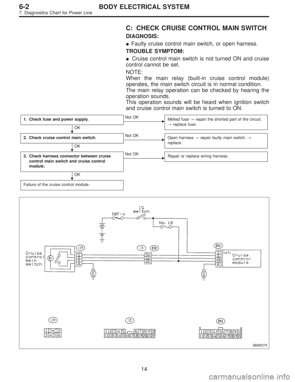
C: CHECK CRUISE CONTROL MAIN SWITCH
DIAGNOSIS:
�Faulty cruise control main switch, or open harness.
TROUBLE SYMPTOM:
�Cruise control main switch is not turned ON and cruise
control cannot be set.
NOTE:
When the main relay (built-in cruise control module)
operates, the main switch circuit is in normal condition.
The main relay operation can be checked by hearing the
operation sounds.
This operation sounds will be heard when ignition switch
and cruise control main switch is turned to ON.
1. Check fuse and power supply.
OK
�Not OK
Melted fuse,repair the shorted part of the circuit.
,replace fuse.
2. Check cruise control main switch.
OK
�Not OK
Open harness,repair faulty main switch.,
replace.
3. Check harness connector between cruise
control main switch and cruise control
module.
OK
�Not OK
Repair or replace wiring harness.
Failure of the cruise control module.
B6M0275
�
�
�
14
6-2BODY ELECTRICAL SYSTEM
7. Diagnostics Chart for Power Line
Page 2712 of 2890
 Check fuse No. 18.
2) Turn ignition switch to ON.
3) Measure voltage between fuse box connector and body.
Connector & terminal / Specified voltage:
(B51) No.")
G6M0181
1. CHECK FUSE AND POWER SUPPLY.
1) Check fuse No. 18.
2) Turn ignition switch to ON.
3) Measure voltage between fuse box connector and body.
Connector & terminal / Specified voltage:
(B51) No. 4—Body / 10 V, or more
B6M0183B
2. CHECK CRUISE CONTROL MAIN SWITCH.
1) Turn ignition switch to OFF.
2) Remove cruise control main switch and disconnect con-
nector.
3) Turn ignition switch to ON.
4) Measure voltage between cruise control main switch
connector and body.
Connector & terminal / Specified voltage:
(i19) No. 3—Body / 10 V, or more
G6M0244
5) Measure resistance between cruise control main switch
terminals.
Terminals / Specified resistance:
No. 3—No. 5 / 10Ω, max. (ON)
1MΩ, min. (OFF)
B6M0184B
3. CHECK HARNESS CONNECTOR BETWEEN
CRUISE CONTROL MAIN SWITCH AND CRUISE
CONTROL MODULE.
1) Connect connector.
2) Turn ignition switch to ON.
3) Turn cruise control main switch to ON.
4) Measure voltage between each terminal of cruise con-
trol main switch or cruise control module and body.
Connector & terminal / Specified voltage:
(i19) No. 3—Body / 10 V, or more
(i19) No. 5—Body / 10 V, or more
(B94) No. 15—Body / 10 V, or more
NOTE:
Depress cruise control main switch with fingers while mea-
suring (i19) No. 5—Body.
15
6-2BODY ELECTRICAL SYSTEM
7. Diagnostics Chart for Power Line
 for disconnection or cracks.
B6M0270A
3. ACTUATOR
1) Disconnect vacuum hose from actuator.
B6M0174")