Page 1800 of 2890
 Prepare Subaru select monitor and cartridge.
ST1 498307500 SELECT MONITOR KIT
ST2 498345700 CARTRIDGE
G3M0150
2) Turn ignition")
OBD0057A
C: SUBARU SELECT MONITOR
1. HOW TO USE SUBARU SELECT MONITOR
1) Prepare Subaru select monitor and cartridge.
ST1 498307500 SELECT MONITOR KIT
ST2 498345700 CARTRIDGE
G3M0150
2) Turn ignition switch and Subaru select monitor switch to
OFF.
3) Insert cartridge into Subaru select monitor.
OBD0059A
4) Connect Subaru select monitor to data link connector.
�Using data link connector for Subaru select monitor
only, connect Subaru select monitor to its data link con-
nector located in the lower portion of the instrument
panel (on the driver’s side), to the side of the center
console box.
OBD0669A
�Using data link connector for Subaru select monitor
and OBD-II general scan tool;
(1) Connect ST to Subaru select monitor cable.
ST 498357200 ADAPTER CABLE
OBD0006C
(2) Open the cover and connect Subaru select monitor
to data link connector located in the lower portion of the
instrument panel (on the driver’s side), to the lower
cover.
CAUTION:
Do not connect scan tools except for Subaru select
monitor and OBD-II general scan tool.
32
2-7ON-BOARD DIAGNOSTICS II SYSTEM
3. Diagnosis System
Page 1828 of 2890
 Insert cartridge into Subaru select monitor.
OBD0005B
4) Connect test mode connector at the lower portion of
instrument panel (on the driver’s side), to the side of the
center console box")
G3M0150
3) Insert cartridge into Subaru select monitor.
OBD0005B
4) Connect test mode connector at the lower portion of
instrument panel (on the driver’s side), to the side of the
center console box.
OBD0059A
5) Connect Subaru select monitor to data link connector.
�Using data link connector for Subaru select monitor only:
Connect Subaru select monitor to its data link connector
located in the lower portion of the instrument panel (on the
driver’s side), to the side of the center console box.
OBD0669A
�Using data link connector for Subaru select monitor and
OBD-II general scan tool:
(1) Connect ST to Subaru select monitor cable.
ST 498357200 ADAPTER CABLE
OBD0006C
(2) Open the cover and connect Subaru select monitor
to data link connector located in the lower portion of the
instrument panel (on the driver’s side), to the lower
cover.
CAUTION:
Do not connect scan tools except for Subaru select
monitor and OBD-II general scan tool.
60
2-7ON-BOARD DIAGNOSTICS II SYSTEM
3. Diagnosis System
Page 1829 of 2890
 Turn ignition switch to ON (engine OFF) and Subaru
select monitor switch to ON.
7) Start the engine.
NOTE:
�Ensure the selector lever is placed in the“P”position
before starting. (AT ve")
OBD0060
6) Turn ignition switch to ON (engine OFF) and Subaru
select monitor switch to ON.
7) Start the engine.
NOTE:
�Ensure the selector lever is placed in the“P”position
before starting. (AT vehicles)
�Depress clutch pedal when starting the engine. (MT
vehicles)
8) Using the selector lever or shift lever, turn the“P”posi-
tion switch and the“N”position switch to ON.
9) Depress the brake pedal to turn the brake switch ON.
(AT vehicles)
10) Keep engine speed in the 2,500—3,000 rpm range
for 40 seconds.
NOTE:
On models without tachometer, use the Subaru select
monitor or tachometer (Secondary pickup type).
11) Place the selector lever or shift lever in the“D”posi-
tion (AT vehicles) or“1st”gear (MT vehicles) and drive the
vehicle at 5 to 10 km/h (3 to 6 MPH).
NOTE:
�On AWD vehicles, release the parking brake.
�The speed difference between front and rear wheels
may light either the ABS or the ABS/TCS warning light, but
this indicates no malfunctions. When engine control diag-
nosis is finished, perform the ABS or the ABS/TCS memory
clearance procedure of self-diagnosis system.
4-4b [T6D2] or [T9K0], 4-4c [T6D2] or [T9J0].>
OBD0005B
3. OBD-II GENERAL SCAN TOOL
After performing diagnostics and clearing the memory,
check for any remaining unresolved trouble data:
1) Connect test mode connector at the lower side of the
instrument panel (on the driver’s side), to the side of the
center console box.
OBD0006C
2) Open the cover and connect the OBD-II general scan
tool to its data link connector in the lower portion of the
instrument panel (on the driver’s side), to the lower cover.
CAUTION:
Do not connect the scan tools except for Subaru select
monitor and OBD-II general scan tool.
61
2-7ON-BOARD DIAGNOSTICS II SYSTEM
3. Diagnosis System
Page 1832 of 2890
 Insert cartridge into Subaru select monitor.
OBD0005B
4) Connect test mode connector at the lower portion of
instrument panel (on the driver’s side), to the side of the
center console box")
G3M0150
3) Insert cartridge into Subaru select monitor.
OBD0005B
4) Connect test mode connector at the lower portion of
instrument panel (on the driver’s side), to the side of the
center console box.
OBD0059A
5) Connect Subaru select monitor to data link connector.
�Using data link connector for Subaru select monitor only:
Connect Subaru select monitor to its data link connector
located in the lower portion of the instrument panel (on the
driver’s side), to the side of the center console box.
OBD0669A
�Using data link connector for Subaru select monitor and
OBD-II general scan tool:
(1) Connect ST to Subaru select monitor cable.
ST1 498357200 ADAPTER CABLE
OBD0006C
(2) Open the cover and connect Subaru select monitor
to data link connector located in the lower portion of the
instrument panel (on the driver’s side), to the lower
cover.
CAUTION:
Do not connect scan tools except for Subaru select
monitor and OBD-II general scan tool.
64
2-7ON-BOARD DIAGNOSTICS II SYSTEM
3. Diagnosis System
Page 1868 of 2890
 Remove plug cord cap from each spark plug.
2) Install new spark plug on plug cord cap.
CAUTION:
Do not remove spark plug from engine.
3) Cont")
OBD0727A
B2M0644A
8D1
CHECK IGNITION SYSTEM FOR SPARKS.
1) Remove plug cord cap from each spark plug.
2) Install new spark plug on plug cord cap.
CAUTION:
Do not remove spark plug from engine.
3) Contact spark plug’s thread portion on engine.
4) While opening throttle valve fully, crank engine to check
that spark occurs at each cylinder.
: Does spark occur at each cylinder?
: Check fuel pump system.
: Go to step8D2.
OBD0123A
8D2CHECK POWER SUPPLY CIRCUIT FOR
IGNITION COIL.
1) Turn ignition switch to OFF.
2) Disconnect connector from ignition coil.
3) Turn ignition switch to ON.
4) Measure power supply voltage between ignition coil
connector and engine ground.
: Connector & terminal
(E12) No. 2 (+)—Engine ground (�):
Is the voltage more than 10 V?
: Go to step8D3.
: Repair harness between ignition coil and ignition
switch connector.
OBD0124
8D3
CHECK IGNITION COIL.
1) Measure resistance between ignition coil terminals to
check primary coil.
: Terminals
No. 2—No. 1:
Is the resistance between 0.4 and 1.0Ω?
: Go to next.
: Replace ignition coil.
100
2-7ON-BOARD DIAGNOSTICS II SYSTEM
8. Diagnostics for Engine Starting Failure
Page 1869 of 2890
: Terminals
No. 2—No. 3:
Is the resistance between 0.4 and 1.0Ω?
: Replace ignition coil.
: Go to next step 2).
OBD0125A
2) Measure resistance between spark plug cord contact
portions to check secondary coil.
: Terminals
#1—#2:
Is the resistance between 18 and 24Ω?
: Go to next.
: Replace ignition coil.
: Terminals
#3—#4:
Is the resistance between 18 and 24Ω?
: Go to step8D4.
: Replace ignition coil.
OBD0126A
8D4CHECK HARNESS BETWEEN IGNITOR
AND IGNITION COIL CONNECTOR.
1) Turn ignition switch to OFF.
2) Disconnect connector from ignitor.
3) Measure resistance of harness connector between igni-
tion coil and ignitor.
: Connector & terminal
(B13) No. 5—(E12) No. 1:
Is the resistance less than 1Ω?
: Go to next.
: Go to next.
: Connector & terminal
(B13) No. 6—(E12) No. 3:
Is the resistance less than 1Ω?
: Go to step8D5.
: Go to next.
101
2-7ON-BOARD DIAGNOSTICS II SYSTEM
8. Diagnostics for Engine Starting Failure
Page 1933 of 2890
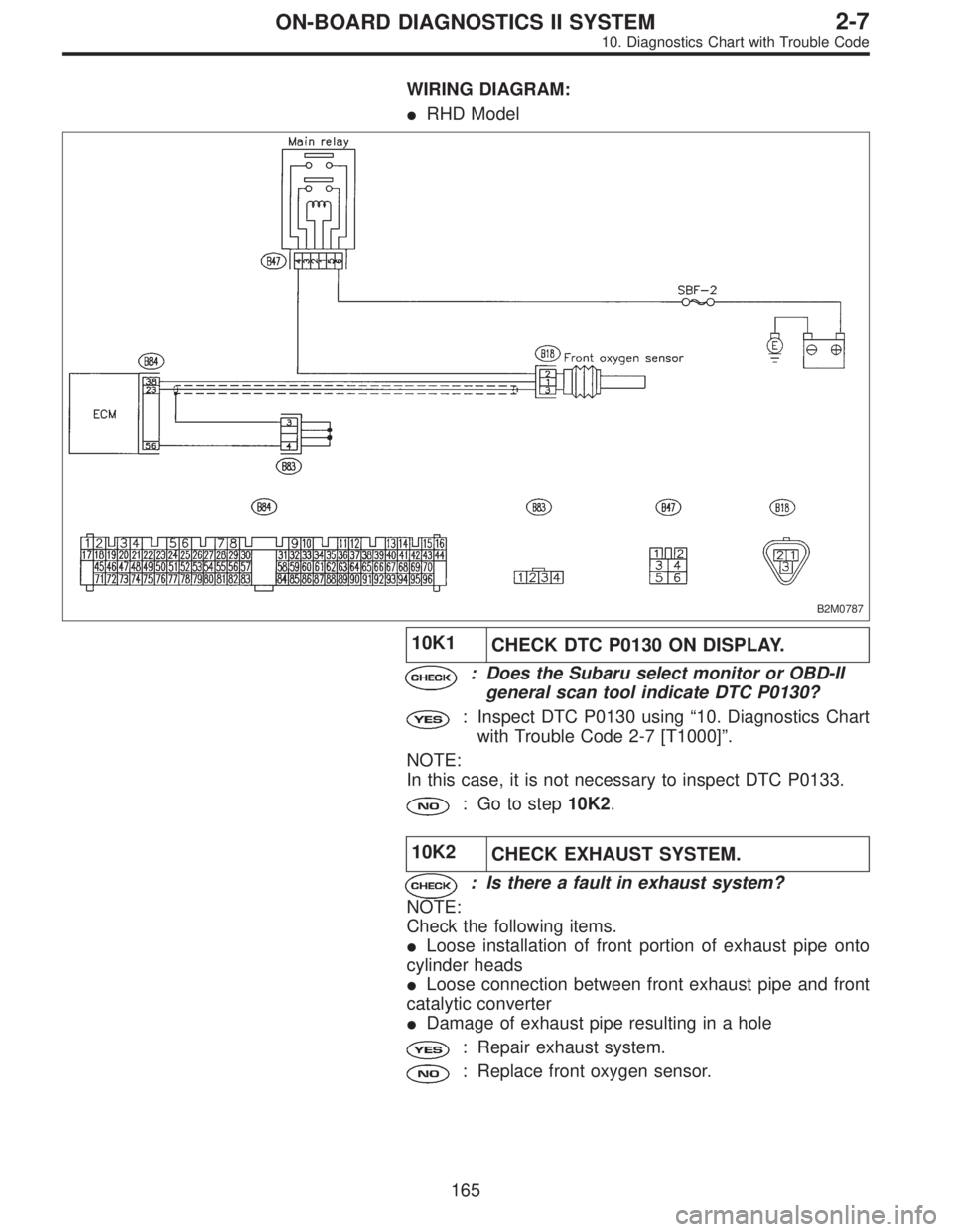
WIRING DIAGRAM:
�RHD Model
B2M0787
10K1
CHECK DTC P0130 ON DISPLAY.
: Does the Subaru select monitor or OBD-II
general scan tool indicate DTC P0130?
: Inspect DTC P0130 using“10. Diagnostics Chart
with Trouble Code 2-7 [T1000]”.
NOTE:
In this case, it is not necessary to inspect DTC P0133.
: Go to step10K2.
10K2
CHECK EXHAUST SYSTEM.
: Is there a fault in exhaust system?
NOTE:
Check the following items.
�Loose installation of front portion of exhaust pipe onto
cylinder heads
�Loose connection between front exhaust pipe and front
catalytic converter
�Damage of exhaust pipe resulting in a hole
: Repair exhaust system.
: Replace front oxygen sensor.
165
2-7ON-BOARD DIAGNOSTICS II SYSTEM
10. Diagnostics Chart with Trouble Code
Page 1944 of 2890

B2M0488
: Is the value fixed between 0.2 and 0.4 V in
function mode F13?
: Go to step10M4.
: Replace rear oxygen sensor.
�OBD-II general scan tool
For detailed operation procedures, refer to the OBD-II Gen-
eral Scan Tool Instruction Manual.
OBD0707C
10M4CHECK HARNESS BETWEEN REAR
OXYGEN SENSOR AND ECM CONNEC-
TOR.
1) Turn ignition switch to OFF.
2) Disconnect connector from rear oxygen sensor.
3) Turn ignition switch to ON.
4) Measure voltage between rear oxygen sensor harness
connector and engine ground or chassis ground.
: Connector & terminal
�2200 cc California model
(B19) No. 4 (+)—Engine ground (�):
�Except 2200 cc California model
(T6) No. 4 (+)—Chassis ground (�):
Is the voltage more than 0.2 V?
: Replace rear oxygen sensor.
: Repair harness and connector.
NOTE:
In this case, repair the following:
�Open circuit in harness between rear oxygen sensor and
ECM connector
�Poor contact in rear oxygen sensor connector
�Poor contact in ECM connector
�Poor contact in rear oxygen sensor connecting harness
connector (Except 2200 cc California model)
10M5
CHECK EXHAUST SYSTEM.
: Is there a fault in exhaust system?
NOTE:
Check the following items.
�Loose installation of portions
�Damage (crack, hole etc.) of parts
�Looseness and ill fitting of parts between front oxygen
sensor and rear oxygen sensor
: Repair or replace faulty parts.
: Replace rear oxygen sensor.
176
2-7ON-BOARD DIAGNOSTICS II SYSTEM
10. Diagnostics Chart with Trouble Code
.
OBD0125A
2) Measure resistance between spark plug cord contact
portions to check sec")