Page 484 of 2890
 O")
1. Engine Lubrication System
Before troubleshooting, make sure that the engine oil level
is correct and no oil leakage exists.
Trouble Possible cause Corrective action
1. Warning light remains
on.1) Oil pressure switch
failureCracked diaphragm or oil leakage within switch Replace.
Broken spring or seized contacts Replace.
2) Low oil pressureClogged oil filter Replace.
Malfunction of oil by-pass valve of oil filter Clean or replace.
Malfunction of oil relief valve of oil pump Clean or replace.
Clogged oil passage Clean.
Excessive tip clearance and side clearance of oil
pump rotor and gearReplace.
Clogged oil strainer or broken pipe Clean or replace.
3) No oil pressureInsufficient engine oil Replenish.
Broken pipe of oil strainer Replace.
Stuck oil pump rotor Replace.
2. Warning light does not
go on.1) Burn-out bulb Replace.
2) Poor contact of switch contact points Replace.
3) Disconnection of wiring Repair.
3. Warning light flickers
momentarily.1) Poor contact at terminals Repair.
2) Defective wiring harness Repair.
3) Low oil pressureCheck for the same pos-
sible causes as listed in
1.—2)
17
2-4DIAGNOSTICS
1. Engine Lubrication System
Page 1419 of 2890

2. Performance Test Diagnosis
If various conditions caused to other air conditioning
system, the characteristics revealed on manifold gauge
reading are shown in the following:
As to the method of a performance test, refer to the item
of“Performance Test”.
Each shaded area on the following tables indicates a read-
ing of the normal system when the temperature of outside
air is 32.5°C (91°F).
Condition Probable cause Corrective action
INSUFFICIENT REFRIGERANT CHARGE
G4M0673
Insufficient cooling Refrigerant is small, or
leaking a little.1. Perform leak test.
2. Repair leak.
3. Charge system.
Evacuate, as
necessary, and
recharge system.
ALMOST NO REFRIGERANT
G4M0674
No cooling action Serious refrigerant leak.Stop compressor
immediately.
1. Perform leak test.
2. Discharge system.
3. Repair leak(s).
4. Replace receiver
drier if necessary.
5. Check oil level.
6. Evacuate and
recharge system.
FAULTY EXPANSION VALVE
G4M0675
Slight cooling;
Sweating or frosted
expansion valve inlet.Expansion valve
restricts refrigerant flow.
�Expansion valve is
clogged.
�Expansion valve is
inoperative.
Valve stuck closed.
Thermal bulb has lost
charge.If valve inlet reveals
sweat or frost:
1. Discharge system.
2. Remove valve and
clean it. Replace it if
necessary.
3. Evacuate system.
4. Charge system.
If valve does not oper-
ate:
1. Discharge system.
2. Replace valve.
3. Evacuate and charge
system.
42
4-7DIAGNOSTICS
2. Performance Test Diagnosis
Page 1654 of 2890
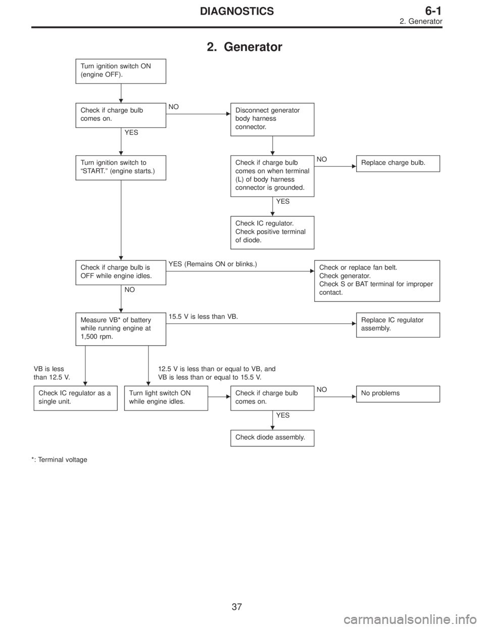
2. Generator
Turn ignition switch ON
(engine OFF).
Check if charge bulb
comes on.
YES
�NO
Disconnect generator
body harness
connector.
Turn ignition switch to
“START.”(engine starts.)Check if charge bulb
comes on when terminal
(L) of body harness
connector is grounded.
YES
�NO
Replace charge bulb.
Check IC regulator.
Check positive terminal
of diode.
Check if charge bulb is
OFF while engine idles.
NO
�YES (Remains ON or blinks.)
Check or replace fan belt.
Check generator.
Check S or BAT terminal for improper
contact.
Measure VB* of battery
while running engine at
1,500 rpm.�15.5 V is less than VB.
Replace IC regulator
assembly.
VB is less
than 12.5 V.12.5 V is less than or equal to VB, and
VB is less than or equal to 15.5 V.
Check IC regulator as a
single unit.
Turn light switch ON
while engine idles.�Check if charge bulb
comes on.
YES
�NO
No problems
Check diode assembly.
*: Terminal voltage
�
��
�
�
�
��
�
37
6-1DIAGNOSTICS
2. Generator
Page 1665 of 2890
 Look at the beam angle gauge (vertical movement).
The bubble on the gauge should not deviate from the cen-
ter of the gauge.
B6M0337A
3) Look at the beam angle gauge (horizontal movement).")
B6M0336A
2) Look at the beam angle gauge (vertical movement).
The bubble on the gauge should not deviate from the cen-
ter of the gauge.
B6M0337A
3) Look at the beam angle gauge (horizontal movement).
The center mark (the red line on the inner scale) should not
deviate from the black line on the outer case.
B: REMOVAL AND INSTALLATION
1. HEADLIGHT BULB
1) Disconnect the connector from inside of the engine
compartment.
2) Remove rubber cap.
3) Remove the light bulb retaining spring to remove the
bulb.
4) Replace the bulb with a new one and hook the spring.
5) Attach the rubber cap and connect the connector.
M6A0139
CAUTION:
�Since the tungsten halogen bulb operates at high
temperature, dirt and oil on the bulb surface decreases
the bulb’s useful life. When replacing the bulb, hold the
flange portion and do not touch the glass portion.
M6A0140
�Attach the rubber cap with letters TOP on the top so
that the drain hole will be on the lower side.
�To keep water out, correctly engage the groove por-
tion of the rubber cap.
9
6-2SERVICE PROCEDURE
4. Headlight
Page 1695 of 2890
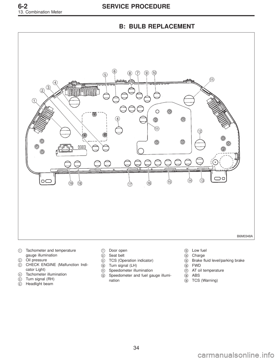
B: BULB REPLACEMENT
B6M0348A
�1Tachometer and temperature
gauge illumination
�
2Oil pressure
�
3CHECK ENGINE (Malfunction Indi-
cator Light)
�
4Tachometer illumination
�
5Turn signal (RH)
�
6Headlight beam�
7Door open
�
8Seat belt
�
9TCS (Operation indicator)
�
10Turn signal (LH)
�
11Speedometer illumination
�
12Speedometer and fuel gauge illumi-
nation�
13Low fuel
�
14Charge
�
15Brake fluid level/parking brake
�
16FWD
�
17AT oil temperature
�
18ABS
�
19TCS (Warning)
34
6-2SERVICE PROCEDURE
13. Combination Meter
Page 1849 of 2890
B2M0510A
7A3CHECK HARNESS BETWEEN COMBINA-
TION METER AND IGNITION SWITCH
CONNECTOR.
1) Turn ignition switch to ON.
2) Measure voltage between combination meter connector
and chassis ground.
: Connector & terminal
(i14) No. 11 (+)—Chassis ground (�):
Is voltage more than 10 V?
: Go to next.
: Check the following and repair if necessary.
�Blown out fuse (No. 15).
NOTE:
If replaced fuse (No. 15) blows easily, check the harness
for short circuit of harness between fuse (No. 15) and com-
bination meter connector.
�Open or short circuit in harness between fuse (No. 15)
and combination meter connector
�Open or short circuit in harness between fuse (No. 15)
and ignition switch connector
�Poor contact in ignition switch connector
: Is there poor contact in combination meter
connector?
: Repair poor contact in combination meter connec-
tor.
: Replace bulb or combination meter.
81
2-7ON-BOARD DIAGNOSTICS II SYSTEM
7. Diagnostics for CHECK ENGINE Malfunction Indicator Lamp (MIL)
Page 2243 of 2890
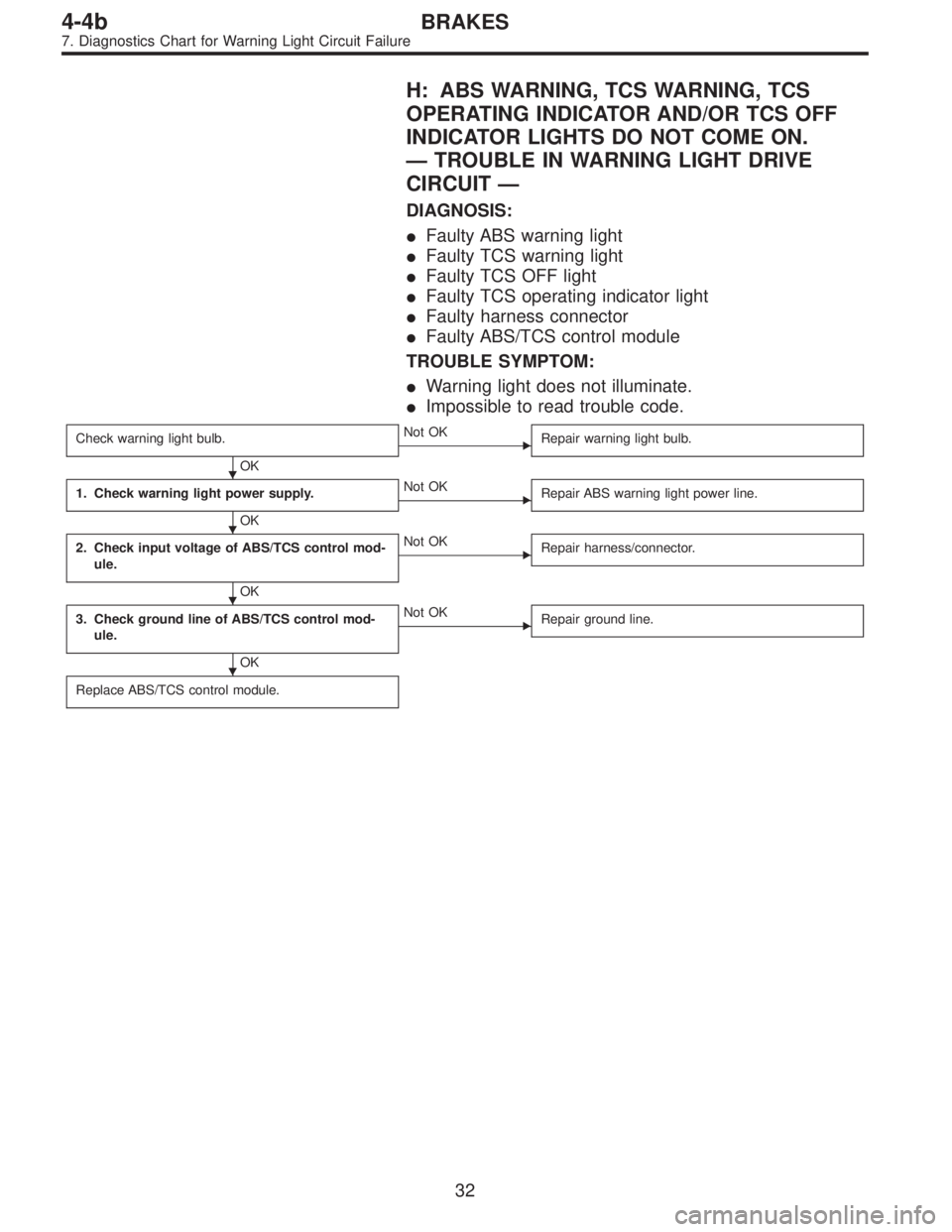
H: ABS WARNING, TCS WARNING, TCS
OPERATING INDICATOR AND/OR TCS OFF
INDICATOR LIGHTS DO NOT COME ON.
—TROUBLE IN WARNING LIGHT DRIVE
CIRCUIT—
DIAGNOSIS:
�Faulty ABS warning light
�Faulty TCS warning light
�Faulty TCS OFF light
�Faulty TCS operating indicator light
�Faulty harness connector
�Faulty ABS/TCS control module
TROUBLE SYMPTOM:
�Warning light does not illuminate.
�Impossible to read trouble code.
Check warning light bulb.
OK
�Not OK
Repair warning light bulb.
1. Check warning light power supply.
OK
�Not OK
Repair ABS warning light power line.
2. Check input voltage of ABS/TCS control mod-
ule.
OK
�Not OK
Repair harness/connector.
3. Check ground line of ABS/TCS control mod-
ule.
OK
�Not OK
Repair ground line.
Replace ABS/TCS control module.
�
�
�
�
32
4-4bBRAKES
7. Diagnostics Chart for Warning Light Circuit Failure
Page 2284 of 2890

1. Check correct installation of stroke sensor.
OK
�Not OK
Repair stroke sensor.
2. Check resistance of stroke sensor.
OK
�Not OK
Replace stroke sensor.
3. Check stroke sensor operation.
OK
�Not OK
Replace stroke sensor.
4. Check body short of stroke sensor.
OK
�Not OK
Replace stroke sensor.
5. Check contact point of stop light switch.
OK
�Not OK
Replace stroke sensor.
6. Check body short of stop light switch.
OK
�Not OK
Replace stroke sensor.
7. Check power supply of stop light switch.
OK
�Not OK
Repair harness/connector.
8. Check input voltage of ABS/TCS control mod-
ule.
OK
�Not OK
Repair harness/connector.
9. Check stop light circuit.
OK
�Not OK
Repair harness/connector.
Replace stop light bulb and/or fuse.
10. Check harness between stroke sensor and
ABS/TCS control module.
OK
�Not OK
Repair harness/connector.
11. Check body short of stroke sensor harness.
OK
�Not OK
Repair harness.
12. Check pump unit operation.
OK
�Not OK
Replace hydraulic unit.
Replace ABS/TCS control module.
�
�
�
�
�
�
�
�
�
�
�
�
73
4-4bBRAKES
8. Diagnostics Chart with Trouble Code
 Turn ignition switch to ON.
2) Measure voltage between combination meter connector
and chassis ground.
: Connect")