1996 CHRYSLER VOYAGER engine
[x] Cancel search: enginePage 1252 of 1938
retainer and plunger spring. Check valve could be
flat or ball.
Assemble tappets in reverse order.
CLEANING AND INSPECTION
CYLINDER HEAD COVERS
Remove any original sealer from the cover sealing
surface of the engine cylinder head.
Remove all residue from the sealing surface using
a clean, dry cloth.
ROCKER ARMS AND PUSH RODS
CLEANING
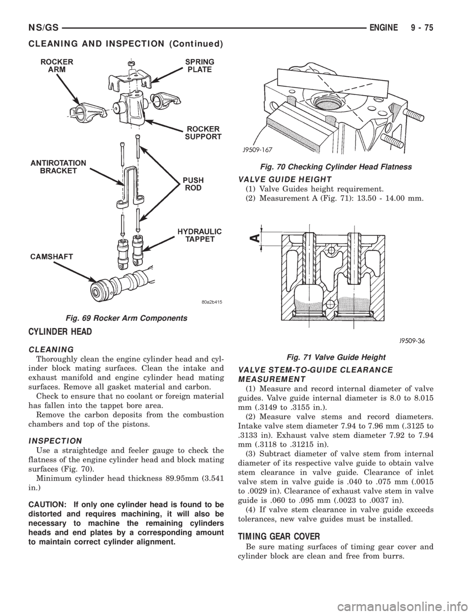
Clean all the components (Fig. 69) with cleaning
solvent.
Use compressed air to blow out the oil passages in
the rocker arms and push rods.
INSPECTION
Inspect the pivot surface area of each rocker arm.
Replace any that are scuffed, pitted, cracked or
excessively worn.
Inspect the valve stem tip contact surface of each
rocker arm and replace any rocker arm that is deeply
pitted.
Inspect each push rod end for excessive wear and
replace as required. If any push rod is excessively
worn because of lack of oil, replace it and inspect the
corresponding hydraulic tappet for excessive wear.
Inspect the push rods for straightness by rolling
them on a flat surface or by shining a light between
the push rod and the flat surface.
A wear pattern along the length of the push rod is
not normal. Inspect the engine cylinder head for
obstruction if this condition exists.
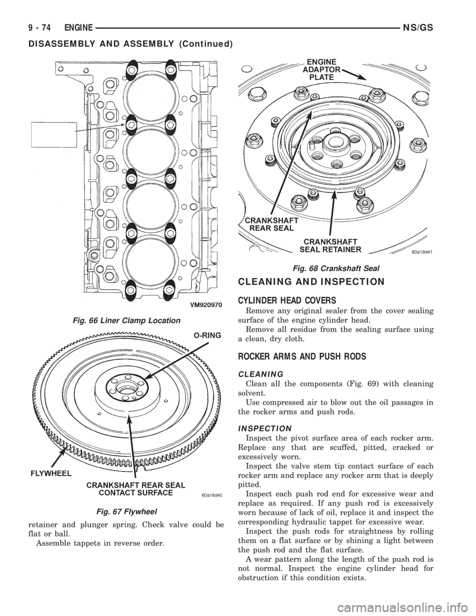
Fig. 66 Liner Clamp Location
Fig. 67 Flywheel
Fig. 68 Crankshaft Seal
9 - 74 ENGINENS/GS
DISASSEMBLY AND ASSEMBLY (Continued)
Page 1253 of 1938
CYLINDER HEAD
CLEANING
Thoroughly clean the engine cylinder head and cyl-
inder block mating surfaces. Clean the intake and
exhaust manifold and engine cylinder head mating
surfaces. Remove all gasket material and carbon.
Check to ensure that no coolant or foreign material
has fallen into the tappet bore area.
Remove the carbon deposits from the combustion
chambers and top of the pistons.
INSPECTION
Use a straightedge and feeler gauge to check the
flatness of the engine cylinder head and block mating
surfaces (Fig. 70).
Minimum cylinder head thickness 89.95mm (3.541
in.)
CAUTION: If only one cylinder head is found to be
distorted and requires machining, it will also be
necessary to machine the remaining cylinders
heads and end plates by a corresponding amount
to maintain correct cylinder alignment.
VALVE GUIDE HEIGHT
(1) Valve Guides height requirement.
(2) Measurement A (Fig. 71): 13.50 - 14.00 mm.
VALVE STEM-TO-GUIDE CLEARANCE
MEASUREMENT
(1) Measure and record internal diameter of valve
guides. Valve guide internal diameter is 8.0 to 8.015
mm (.3149 to .3155 in.).
(2) Measure valve stems and record diameters.
Intake valve stem diameter 7.94 to 7.96 mm (.3125 to
.3133 in). Exhaust valve stem diameter 7.92 to 7.94
mm (.3118 to .31215 in).
(3) Subtract diameter of valve stem from internal
diameter of its respective valve guide to obtain valve
stem clearance in valve guide. Clearance of inlet
valve stem in valve guide is .040 to .075 mm (.0015
to .0029 in). Clearance of exhaust valve stem in valve
guide is .060 to .095 mm (.0023 to .0037 in).
(4) If valve stem clearance in valve guide exceeds
tolerances, new valve guides must be installed.
TIMING GEAR COVER
Be sure mating surfaces of timing gear cover and
cylinder block are clean and free from burrs.
Fig. 69 Rocker Arm Components
Fig. 70 Checking Cylinder Head Flatness
Fig. 71 Valve Guide Height
NS/GSENGINE 9 - 75
CLEANING AND INSPECTION (Continued)
Page 1254 of 1938

VALVES AND VALVE SPRINGS
VALVE CLEANING
Clean all carbon deposits from the combustion
chambers, valve ports, valve stems, valve stem
guides and heads.
Clean all grime and gasket material from the
engine cylinder head machined gasket surfaces.
INSPECTION
Inspect for cracks in the combustion chambers and
valve ports.
Inspect for cracks on the exhaust seat.
Inspect for cracks in the gasket surface at each
coolant passage.
Inspect valves for burned, cracked or warped
heads.
Inspect for scuffed or bent valve stems.
Replace valves displaying any damage.
Check valve spring height. (Fig. 72).
HYDRAULIC TAPPETS
(1) Clean all tappet parts in a solvent that will
remove all varnish and carbon.
(2) Replace tappets that are unfit for further ser-
vice with new assemblies.
(3) If plunger shows signs of scoring or wear,
install a new tappet assembly. If valve is pitted, or
valve seat on end of plunger is prevented from seat-
ing, install a new tappet assembly.
OIL PUMP
CLEANING
Wash all parts in a suitable solvent and inspect
carefully for damage or wear (Fig. 74).
INSPECTION
(1) Before installing oil pump check pump bore
depth in block (A) and pump body height (B) (Fig.
73). Difference between A and B should be
0.020-0.082 mm.
(2) Check clearance between rotors (Fig. 75).
PISTON AND CONNECTING ROD
PISTONS
(1) Piston Diameter: Size Group A: 91.93-91.94mm
(3.6191-3.6196 in.) Size Group B: 91.94-91.95mm
Fig. 72 Valve Spring Chart
Fig. 73 Oil Pump Bore Depth
Fig. 74 Oil Pump Inner and Outer Rotors
9 - 76 ENGINENS/GS
CLEANING AND INSPECTION (Continued)
Page 1255 of 1938
(3.6196-3.6200 in.). Maximum wear limit .05mm
(.0019 in.).
(2) Check piston pin bores in piston for roundness.
Make 3 checks at 120É intervals. Maximum out of
roundness .05mm (.0019in.).
(3) The piston diameter should be measured
approximately 15 mm (.590 in.) up from the base.
(4) Skirt wear should not exceed 0.1 mm (.00039
in.).
(5) The clearance between the cylinder liner and
piston should not exceed 0.25 mm (.0009 in.).
(6) Make sure the weight of the pistons does not
differ by more than 5 g.
CONNECTING ROD
(1) Assemble bearing shells and bearing caps to
their respective connecting rods ensuring that the
serrations on the cap and reference marks are
aligned.
(2) Tighten bearing cap bolts to 29 N´m (21 ft. lbs.)
plus 60É.
(3) Check and record internal diameter of crank
end of connecting rod.
Note: When changing connecting rods, all four
must have the same weight and be stamped with the
same number.Replacement connecting rods will
only be supplied in sets of four.
(4) Connecting rods are supplied in sets of four
since they all must be of the same weight category.
Max allowable weight difference is 18 gr.NOTE:On
one side of the big end of the con-rod there is a two-
digit number which refers to the weight category. On
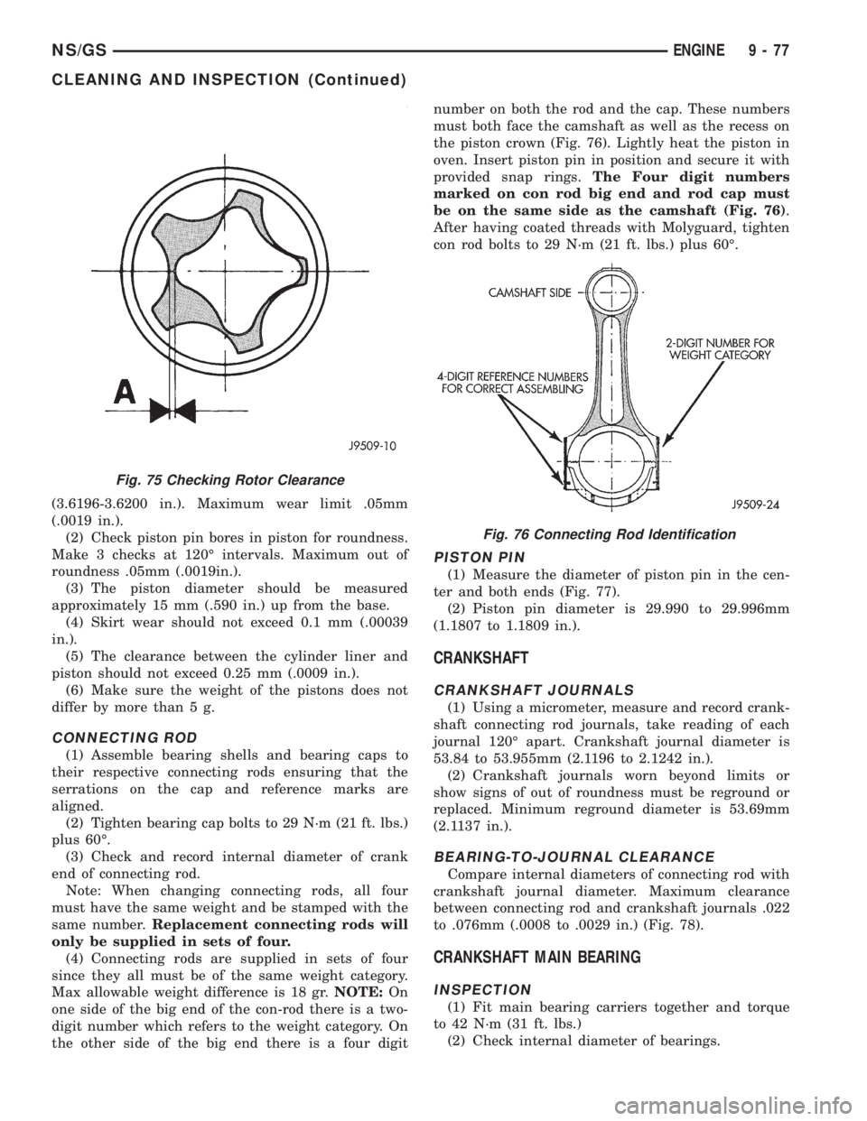
the other side of the big end there is a four digitnumber on both the rod and the cap. These numbers
must both face the camshaft as well as the recess on
the piston crown (Fig. 76). Lightly heat the piston in
oven. Insert piston pin in position and secure it with
provided snap rings.The Four digit numbers
marked on con rod big end and rod cap must
be on the same side as the camshaft (Fig. 76).
After having coated threads with Molyguard, tighten
con rod bolts to 29 N´m (21 ft. lbs.) plus 60É.
PISTON PIN
(1) Measure the diameter of piston pin in the cen-
ter and both ends (Fig. 77).
(2) Piston pin diameter is 29.990 to 29.996mm
(1.1807 to 1.1809 in.).
CRANKSHAFT
CRANKSHAFT JOURNALS
(1) Using a micrometer, measure and record crank-
shaft connecting rod journals, take reading of each
journal 120É apart. Crankshaft journal diameter is
53.84 to 53.955mm (2.1196 to 2.1242 in.).
(2) Crankshaft journals worn beyond limits or
show signs of out of roundness must be reground or
replaced. Minimum reground diameter is 53.69mm
(2.1137 in.).
BEARING-TO-JOURNAL CLEARANCE
Compare internal diameters of connecting rod with
crankshaft journal diameter. Maximum clearance
between connecting rod and crankshaft journals .022
to .076mm (.0008 to .0029 in.) (Fig. 78).
CRANKSHAFT MAIN BEARING
INSPECTION
(1) Fit main bearing carriers together and torque
to 42 N´m (31 ft. lbs.)
(2) Check internal diameter of bearings.
Fig. 75 Checking Rotor Clearance
Fig. 76 Connecting Rod Identification
NS/GSENGINE 9 - 77
CLEANING AND INSPECTION (Continued)
Page 1256 of 1938
(3) If internal diameter of original bearing is being
checked and figures are not within specifications,
new bearings must be used.
(4) Check crankshaft main bearing journals to
bearing clearances. Clearances of main bearings is
.03 to .088mm (.0011 to .0035 in.).
OIL PAN
Remove all gasket material from cylinder block. Be
careful not gouge pan sealing surface.
CYLINDER LINER
INSPECTION
The cylinder walls should be checked for out-of-
round and taper with dail bore gauge. The cylinder
bore out-of-round is 0.100 mm (.0039 inch) maximum
and cylinder bore taper is 0.100 mm (0.0039 inch)
maximum. If the cylinder walls are badly scuffed or
scored, new liners should be installed and honed, and
new pistons and rings fitted.
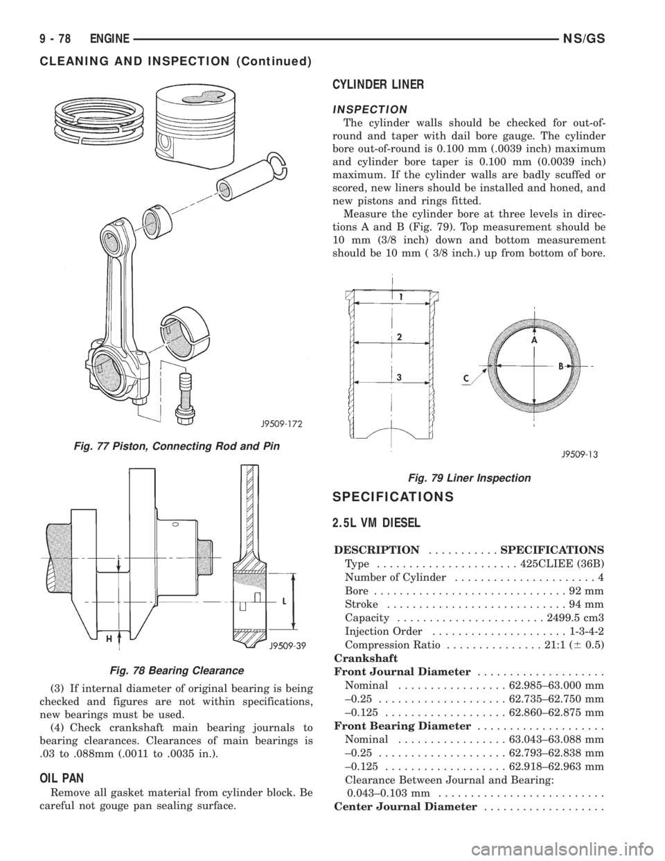
Measure the cylinder bore at three levels in direc-
tions A and B (Fig. 79). Top measurement should be
10 mm (3/8 inch) down and bottom measurement
should be 10 mm ( 3/8 inch.) up from bottom of bore.
SPECIFICATIONS
2.5L VM DIESEL
DESCRIPTION...........SPECIFICATIONS
Type ......................425CLIEE (36B)
Number of Cylinder......................4
Bore..............................92mm
Stroke............................94mm
Capacity.......................2499.5 cm3
Injection Order.....................1-3-4-2
Compression Ratio...............21:1 (60.5)
Crankshaft
Front Journal Diameter....................
Nominal.................62.985±63.000 mm
±0.25....................62.735±62.750 mm
±0.125...................62.860±62.875 mm
Front Bearing Diameter....................
Nominal.................63.043±63.088 mm
±0.25....................62.793±62.838 mm
±0.125...................62.918±62.963 mm
Clearance Between Journal and Bearing:
0.043±0.103 mm..........................
Center Journal Diameter...................
Fig. 77 Piston, Connecting Rod and Pin
Fig. 78 Bearing Clearance
Fig. 79 Liner Inspection
9 - 78 ENGINENS/GS
CLEANING AND INSPECTION (Continued)
Page 1257 of 1938
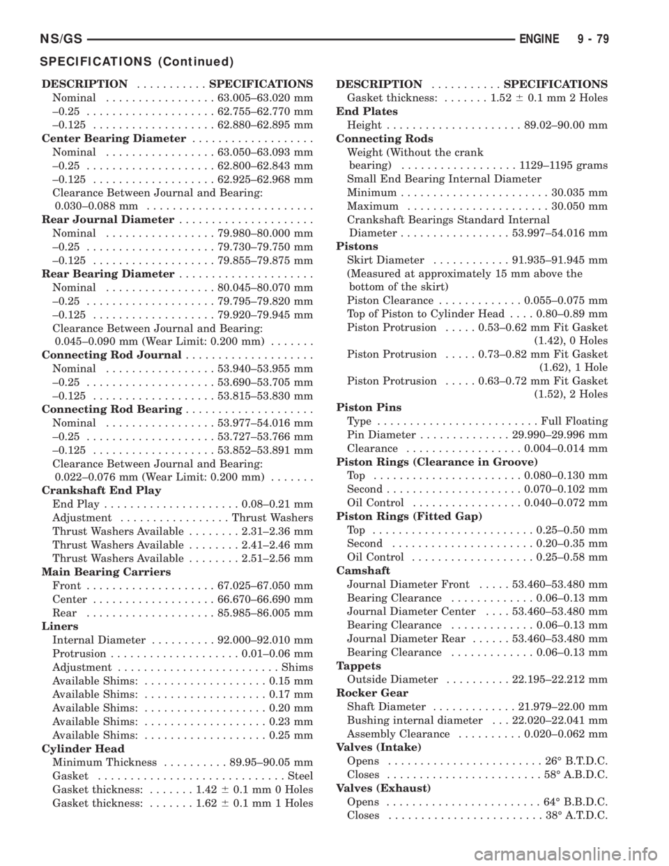
DESCRIPTION...........SPECIFICATIONS
Nominal.................63.005±63.020 mm
±0.25....................62.755±62.770 mm
±0.125...................62.880±62.895 mm
Center Bearing Diameter...................
Nominal.................63.050±63.093 mm
±0.25....................62.800±62.843 mm
±0.125...................62.925±62.968 mm
Clearance Between Journal and Bearing:
0.030±0.088 mm..........................
Rear Journal Diameter.....................
Nominal.................79.980±80.000 mm
±0.25....................79.730±79.750 mm
±0.125...................79.855±79.875 mm
Rear Bearing Diameter.....................
Nominal.................80.045±80.070 mm
±0.25....................79.795±79.820 mm
±0.125...................79.920±79.945 mm
Clearance Between Journal and Bearing:
0.045±0.090 mm (Wear Limit: 0.200 mm).......
Connecting Rod Journal....................
Nominal.................53.940±53.955 mm
±0.25....................53.690±53.705 mm
±0.125...................53.815±53.830 mm
Connecting Rod Bearing....................
Nominal.................53.977±54.016 mm
±0.25....................53.727±53.766 mm
±0.125...................53.852±53.891 mm
Clearance Between Journal and Bearing:
0.022±0.076 mm (Wear Limit: 0.200 mm).......
Crankshaft End Play
End Play.....................0.08±0.21 mm
Adjustment.................Thrust Washers
Thrust Washers Available........2.31±2.36 mm
Thrust Washers Available........2.41±2.46 mm
Thrust Washers Available........2.51±2.56 mm
Main Bearing Carriers
Front....................67.025±67.050 mm
Center...................66.670±66.690 mm
Rear....................85.985±86.005 mm
Liners
Internal Diameter..........92.000±92.010 mm
Protrusion....................0.01±0.06 mm
Adjustment.........................Shims
Available Shims:...................0.15 mm
Available Shims:...................0.17 mm
Available Shims:...................0.20 mm
Available Shims:...................0.23 mm
Available Shims:...................0.25 mm
Cylinder Head
Minimum Thickness..........89.95±90.05 mm
Gasket.............................Steel
Gasket thickness:.......1.4260.1 mm 0 Holes
Gasket thickness:.......1.6260.1 mm 1 HolesDESCRIPTION...........SPECIFICATIONS
Gasket thickness:.......1.5260.1 mm 2 Holes
End Plates
Height.....................89.02±90.00 mm
Connecting Rods
Weight (Without the crank
bearing)..................1129±1195 grams
Small End Bearing Internal Diameter
Minimum.......................30.035 mm
Maximum......................30.050 mm
Crankshaft Bearings Standard Internal
Diameter.................53.997±54.016 mm
Pistons
Skirt Diameter............91.935±91.945 mm
(Measured at approximately 15 mm above the
bottom of the skirt)
Piston Clearance.............0.055±0.075 mm
Top of Piston to Cylinder Head....0.80±0.89 mm
Piston Protrusion.....0.53±0.62 mm Fit Gasket
(1.42), 0 Holes
Piston Protrusion.....0.73±0.82 mm Fit Gasket
(1.62), 1 Hole
Piston Protrusion.....0.63±0.72 mm Fit Gasket
(1.52), 2 Holes
Piston Pins
Type .........................Full Floating
Pin Diameter..............29.990±29.996 mm
Clearance..................0.004±0.014 mm
Piston Rings (Clearance in Groove)
Top .......................0.080±0.130 mm
Second.....................0.070±0.102 mm
Oil Control.................0.040±0.072 mm
Piston Rings (Fitted Gap)
Top .........................0.25±0.50 mm
Second......................0.20±0.35 mm
Oil Control...................0.25±0.58 mm
Camshaft
Journal Diameter Front.....53.460±53.480 mm
Bearing Clearance.............0.06±0.13 mm
Journal Diameter Center....53.460±53.480 mm
Bearing Clearance.............0.06±0.13 mm
Journal Diameter Rear......53.460±53.480 mm
Bearing Clearance.............0.06±0.13 mm
Tappets
Outside Diameter..........22.195±22.212 mm
Rocker Gear
Shaft Diameter.............21.979±22.00 mm
Bushing internal diameter . . . 22.020±22.041 mm
Assembly Clearance..........0.020±0.062 mm
Valves (Intake)
Opens........................26ÉB.T.D.C.
Closes........................58ÉA.B.D.C.
Valves (Exhaust)
Opens........................64ÉB.B.D.C.
Closes........................38ÉA.T.D.C.
NS/GSENGINE 9 - 79
SPECIFICATIONS (Continued)
Page 1258 of 1938
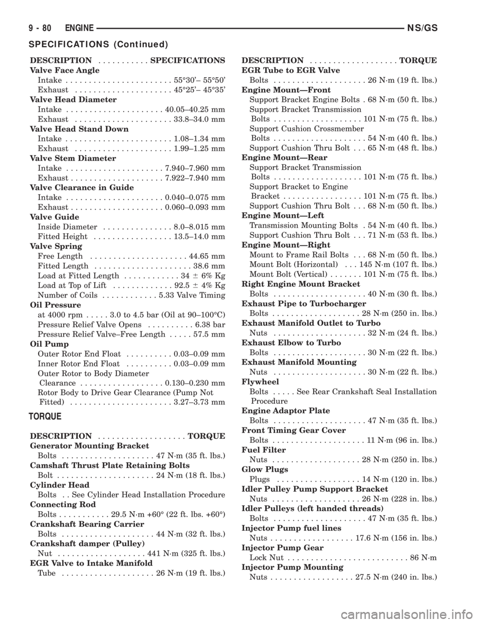
DESCRIPTION...........SPECIFICATIONS
Valve Face Angle
Intake.......................55É30'± 55É50'
Exhaust.....................45É25'± 45É35'
Valve Head Diameter
Intake.....................40.05±40.25 mm
Exhaust.....................33.8±34.0 mm
Valve Head Stand Down
Intake.......................1.08±1.34 mm
Exhaust.....................1.99±1.25 mm
Valve Stem Diameter
Intake.....................7.940±7.960 mm
Exhaust....................7.922±7.940 mm
Valve Clearance in Guide
Intake.....................0.040±0.075 mm
Exhaust....................0.060±0.093 mm
Valve Guide
Inside Diameter...............8.0±8.015 mm
Fitted Height.................13.5±14.0 mm
Valve Spring
Free Length.....................44.65 mm
Fitted Length.....................38.6 mm
Load at Fitted Length............3466% Kg
Load at Top of Lift.............92.564% Kg
Number of Coils............5.33 Valve Timing
Oil Pressure
at 4000 rpm.....3.0to4.5bar(Oil at 90±100ÉC)
Pressure Relief Valve Opens..........6.38 bar
Pressure Relief Valve±Free Length.....57.5 mm
Oil Pump
Outer Rotor End Float..........0.03±0.09 mm
Inner Rotor End Float..........0.03±0.09 mm
Outer Rotor to Body Diameter
Clearance..................0.130±0.230 mm
Rotor Body to Drive Gear Clearance (Pump Not
Fitted)......................3.27±3.73 mm
TORQUE
DESCRIPTION...................TORQUE
Generator Mounting Bracket
Bolts....................47N´m(35ft.lbs.)
Camshaft Thrust Plate Retaining Bolts
Bolt.....................24N´m(18ft.lbs.)
Cylinder Head
Bolts . . See Cylinder Head Installation Procedure
Connecting Rod
Bolts...........29.5 N´m +60É (22 ft. lbs. +60É)
Crankshaft Bearing Carrier
Bolts....................44N´m(32ft.lbs.)
Crankshaft damper (Pulley)
Nut ...................441N´m(325 ft. lbs.)
EGR Valve to Intake Manifold
Tube ....................26N´m(19ft.lbs.)DESCRIPTION...................TORQUE
EGR Tube to EGR Valve
Bolts....................26N´m(19ft.lbs.)
Engine MountÐFront
Support Bracket Engine Bolts . 68 N´m (50 ft. lbs.)
Support Bracket Transmission
Bolts...................101N´m(75ft.lbs.)
Support Cushion Crossmember
Bolts....................54N´m(40ft.lbs.)
Support Cushion Thru Bolt . . . 65 N´m (48 ft. lbs.)
Engine MountÐRear
Support Bracket Transmission
Bolts...................101N´m(75ft.lbs.)
Support Bracket to Engine
Bracket.................101N´m(75ft.lbs.)
Support Cushion Thru Bolt . . . 68 N´m (50 ft. lbs.)
Engine MountÐLeft
Transmission Mounting Bolts . 54 N´m (40 ft. lbs.)
Support Cushion Thru Bolt . . . 71 N´m (53 ft. lbs.)
Engine MountÐRight
Mount to Frame Rail Bolts . . . 68 N´m (50 ft. lbs.)
Mount Bolt (Horizontal) . . . 145 N´m (107 ft. lbs.)
Mount Bolt (Vertical).......101N´m(75ft.lbs.)
Right Engine Mount Bracket
Bolts....................40N´m(30ft.lbs.)
Exhaust Pipe to Turbocharger
Bolts...................28N´m(250 in. lbs.)
Exhaust Manifold Outlet to Turbo
Nuts....................32N´m(24ft.lbs.)
Exhaust Elbow to Turbo
Bolts....................30N´m(22ft.lbs.)
Exhaust Manifold Mounting
Nuts....................30N´m(22ft.lbs.)
Flywheel
Bolts.....SeeRear Crankshaft Seal Installation
Procedure
Engine Adaptor Plate
Bolts....................47N´m(35ft.lbs.)
Front Timing Gear Cover
Bolts....................11N´m(96in.lbs.)
Fuel Filter
Nuts...................28N´m(250 in. lbs.)
Glow Plugs
Plugs..................14N´m(120 in. lbs.)
Idler Pulley Pump Support Bracket
Nuts...................26N´m(228 in. lbs.)
Idler Pulleys (left handed threads)
Bolts....................47N´m(35ft.lbs.)
Injector Pump fuel lines
Nuts..................17.6 N´m (156 in. lbs.)
Injector Pump Gear
Lock Nut..........................86N´m
Injector Pump Mounting
Nuts..................27.5 N´m (240 in. lbs.)
9 - 80 ENGINENS/GS
SPECIFICATIONS (Continued)
Page 1259 of 1938
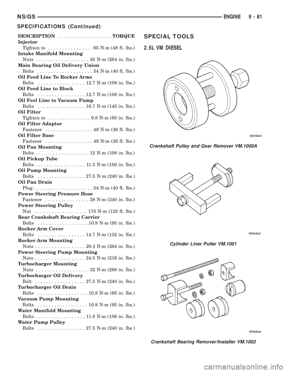
DESCRIPTION...................TORQUE
Injector
Tighten to................65N´m(48ft.lbs.)
Intake Manifold Mounting
Nuts...................30N´m(264 in. lbs.)
Main Bearing Oil Delivery Union
Bolts....................54N´m(40ft.lbs.)
Oil Feed Line To Rocker Arms
Bolts.................12.7 N´m (108 in. lbs.)
Oil Feed Line to Block
Bolts.................12.7 N´m (108 in. lbs.)
Oil Feel Line to Vacuum Pump
Bolts.................16.7 N´m (145 in. lbs.)
Oil Filter
Tighten to...............9.8N´m(85in.lbs.)
Oil Filter Adaptor
Fastener.................49N´m(36ft.lbs.)
Oil Filter Base
Fastener.................49N´m(36ft.lbs.)
Oil Pan Mounting
Bolts...................12N´m(108 in. lbs.)
Oil Pickup Tube
Bolts..................11.3N´m(100 in. lbs.)
Oil Pump Mounting
Bolts.................27.5 N´m (240 in. lbs.)
Oil Pan Drain
Plug.....................54N´m(40ft.lbs.)
Power Steering Pressure Hose
Fastener................28N´m(240 in. lbs.)
Power Steering Pulley
Nut ...................170N´m(125 ft. lbs.)
Rear Crankshaft Bearing Carrier
Bolts..................10.8 N´m (95 in. lbs.)
Rocker Arm Cover
Bolts.................14.7 N´m (132 in. lbs.)
Rocker Arm Mounting
Nuts..................29.4 N´m (264 in. lbs.)
Power Steering Pump Mounting
Nuts..................24.5 N´m (216 in. lbs.)
Turbocharger Mounting
Nuts...................32N´m(288 in. lbs.)
Turbocharger Oil Delivery
Bolt..................27.5 N´m (240 in. lbs.)
Turbocharger Oil Drain
Bolts..................10.8 N´m (95 in. lbs.)
Vacuum Pump Mounting
Bolts..................10.8 N´m (95 in. lbs.)
Water Manifold Mounting
Bolts..................11.8N´m(108 in. lbs.)
Water Pump Pulley
Bolts.................27.5 N´m (240 in. lbs.)SPECIAL TOOLS
2.5L VM DIESEL
Crankshaft Pulley and Gear Remover VM.1000A
Cylinder Liner Puller VM.1001
Crankshaft Bearing Remover/Installer VM.1002
NS/GSENGINE 9 - 81
SPECIFICATIONS (Continued)