1996 CHRYSLER VOYAGER engine
[x] Cancel search: enginePage 1228 of 1938
VALVE STAND DOWN
Valve stand down is to maintain the adequate com-
pression ratio.
(1) Invert cylinder head.
(2) Fit each valve to its respective valve guide.
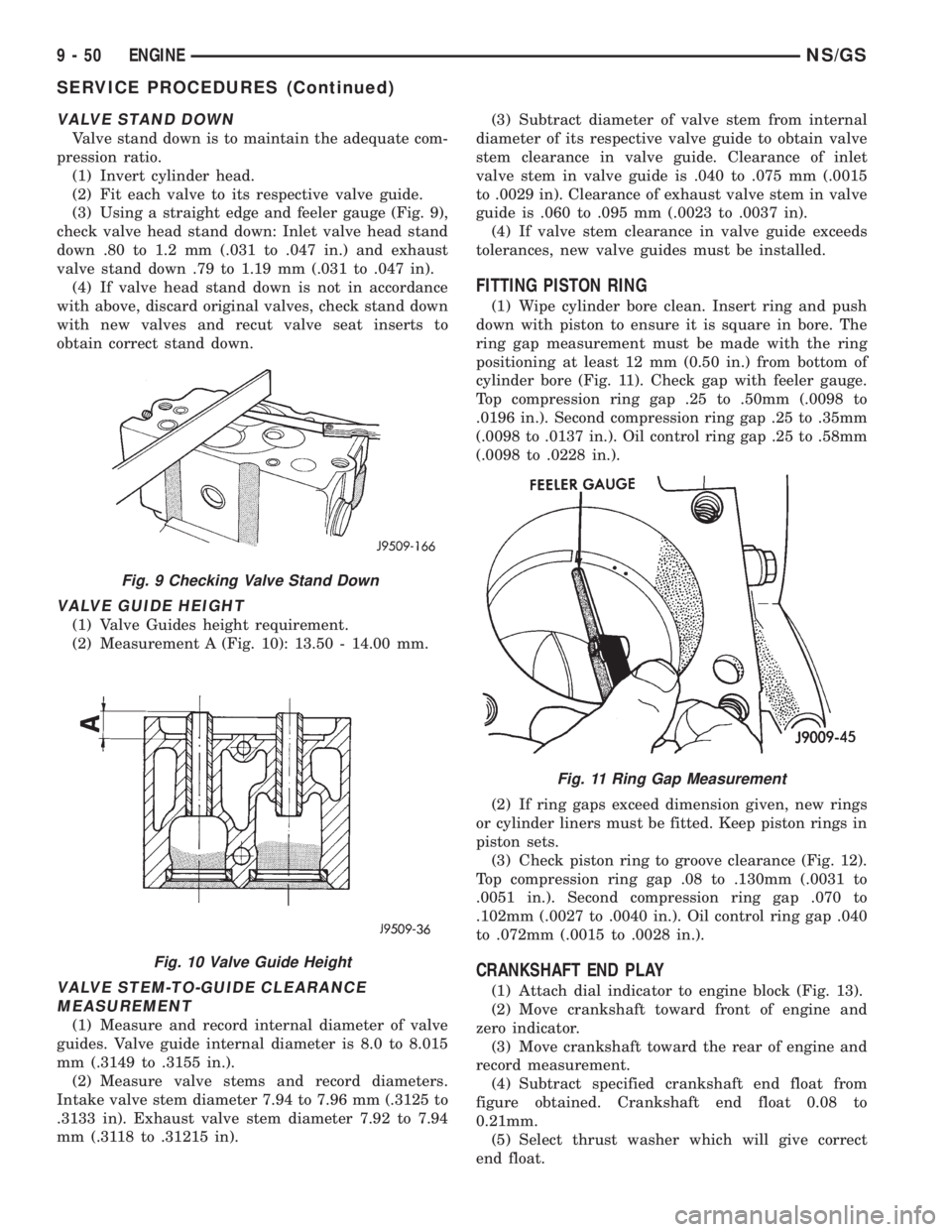
(3) Using a straight edge and feeler gauge (Fig. 9),
check valve head stand down: Inlet valve head stand
down .80 to 1.2 mm (.031 to .047 in.) and exhaust
valve stand down .79 to 1.19 mm (.031 to .047 in).
(4) If valve head stand down is not in accordance
with above, discard original valves, check stand down
with new valves and recut valve seat inserts to
obtain correct stand down.
VALVE GUIDE HEIGHT
(1) Valve Guides height requirement.
(2) Measurement A (Fig. 10): 13.50 - 14.00 mm.
VALVE STEM-TO-GUIDE CLEARANCE
MEASUREMENT
(1) Measure and record internal diameter of valve
guides. Valve guide internal diameter is 8.0 to 8.015
mm (.3149 to .3155 in.).
(2) Measure valve stems and record diameters.
Intake valve stem diameter 7.94 to 7.96 mm (.3125 to
.3133 in). Exhaust valve stem diameter 7.92 to 7.94
mm (.3118 to .31215 in).(3) Subtract diameter of valve stem from internal
diameter of its respective valve guide to obtain valve
stem clearance in valve guide. Clearance of inlet
valve stem in valve guide is .040 to .075 mm (.0015
to .0029 in). Clearance of exhaust valve stem in valve
guide is .060 to .095 mm (.0023 to .0037 in).
(4) If valve stem clearance in valve guide exceeds
tolerances, new valve guides must be installed.
FITTING PISTON RING
(1) Wipe cylinder bore clean. Insert ring and push
down with piston to ensure it is square in bore. The
ring gap measurement must be made with the ring
positioning at least 12 mm (0.50 in.) from bottom of
cylinder bore (Fig. 11). Check gap with feeler gauge.
Top compression ring gap .25 to .50mm (.0098 to
.0196 in.). Second compression ring gap .25 to .35mm
(.0098 to .0137 in.). Oil control ring gap .25 to .58mm
(.0098 to .0228 in.).
(2) If ring gaps exceed dimension given, new rings
or cylinder liners must be fitted. Keep piston rings in
piston sets.
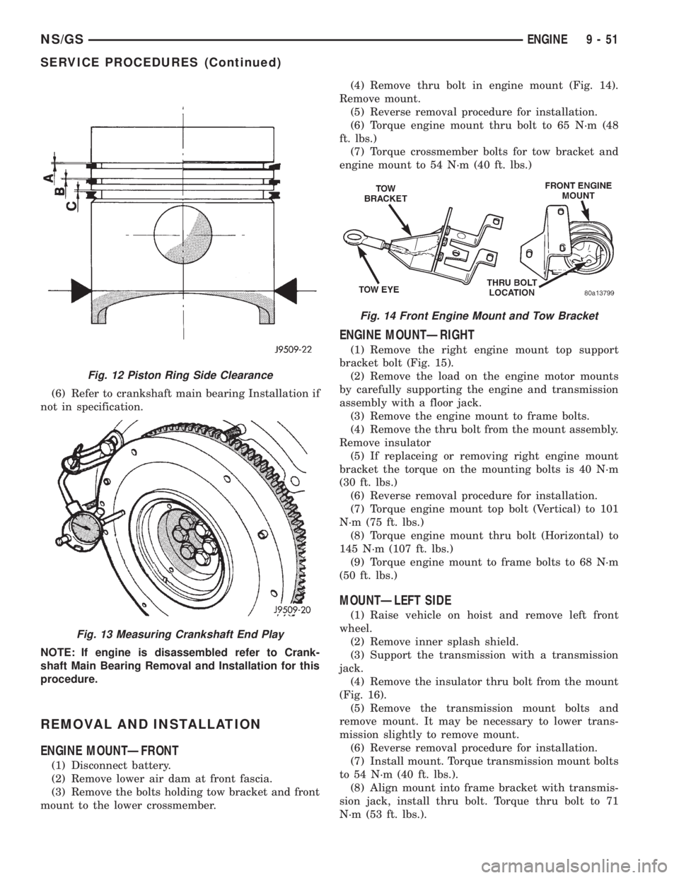
(3) Check piston ring to groove clearance (Fig. 12).
Top compression ring gap .08 to .130mm (.0031 to
.0051 in.). Second compression ring gap .070 to
.102mm (.0027 to .0040 in.). Oil control ring gap .040
to .072mm (.0015 to .0028 in.).
CRANKSHAFT END PLAY
(1) Attach dial indicator to engine block (Fig. 13).
(2) Move crankshaft toward front of engine and
zero indicator.
(3) Move crankshaft toward the rear of engine and
record measurement.
(4) Subtract specified crankshaft end float from
figure obtained. Crankshaft end float 0.08 to
0.21mm.
(5) Select thrust washer which will give correct
end float.
Fig. 9 Checking Valve Stand Down
Fig. 10 Valve Guide Height
Fig. 11 Ring Gap Measurement
9 - 50 ENGINENS/GS
SERVICE PROCEDURES (Continued)
Page 1229 of 1938
(6) Refer to crankshaft main bearing Installation if
not in specification.
NOTE: If engine is disassembled refer to Crank-
shaft Main Bearing Removal and Installation for this
procedure.
REMOVAL AND INSTALLATION
ENGINE MOUNTÐFRONT
(1) Disconnect battery.
(2) Remove lower air dam at front fascia.
(3) Remove the bolts holding tow bracket and front
mount to the lower crossmember.(4) Remove thru bolt in engine mount (Fig. 14).
Remove mount.
(5) Reverse removal procedure for installation.
(6) Torque engine mount thru bolt to 65 N´m (48
ft. lbs.)
(7) Torque crossmember bolts for tow bracket and
engine mount to 54 N´m (40 ft. lbs.)
ENGINE MOUNTÐRIGHT
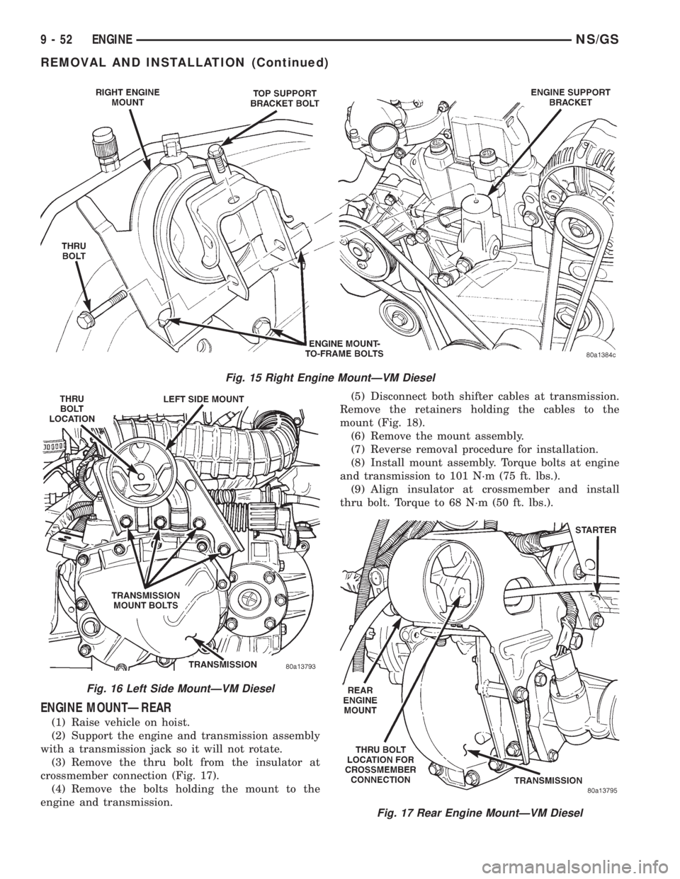
(1) Remove the right engine mount top support
bracket bolt (Fig. 15).
(2) Remove the load on the engine motor mounts
by carefully supporting the engine and transmission
assembly with a floor jack.
(3) Remove the engine mount to frame bolts.
(4) Remove the thru bolt from the mount assembly.
Remove insulator
(5) If replaceing or removing right engine mount
bracket the torque on the mounting bolts is 40 N´m
(30 ft. lbs.)
(6) Reverse removal procedure for installation.
(7) Torque engine mount top bolt (Vertical) to 101
N´m (75 ft. lbs.)
(8) Torque engine mount thru bolt (Horizontal) to
145 N´m (107 ft. lbs.)
(9) Torque engine mount to frame bolts to 68 N´m
(50 ft. lbs.)
MOUNTÐLEFT SIDE
(1) Raise vehicle on hoist and remove left front
wheel.
(2) Remove inner splash shield.
(3) Support the transmission with a transmission
jack.
(4) Remove the insulator thru bolt from the mount
(Fig. 16).
(5) Remove the transmission mount bolts and
remove mount. It may be necessary to lower trans-
mission slightly to remove mount.
(6) Reverse removal procedure for installation.
(7) Install mount. Torque transmission mount bolts
to 54 N´m (40 ft. lbs.).
(8) Align mount into frame bracket with transmis-
sion jack, install thru bolt. Torque thru bolt to 71
N´m (53 ft. lbs.).
Fig. 12 Piston Ring Side Clearance
Fig. 13 Measuring Crankshaft End Play
Fig. 14 Front Engine Mount and Tow Bracket
NS/GSENGINE 9 - 51
SERVICE PROCEDURES (Continued)
Page 1230 of 1938
ENGINE MOUNTÐREAR
(1) Raise vehicle on hoist.
(2) Support the engine and transmission assembly
with a transmission jack so it will not rotate.
(3) Remove the thru bolt from the insulator at
crossmember connection (Fig. 17).
(4) Remove the bolts holding the mount to the
engine and transmission.(5) Disconnect both shifter cables at transmission.
Remove the retainers holding the cables to the
mount (Fig. 18).
(6) Remove the mount assembly.
(7) Reverse removal procedure for installation.
(8) Install mount assembly. Torque bolts at engine
and transmission to 101 N´m (75 ft. lbs.).
(9) Align insulator at crossmember and install
thru bolt. Torque to 68 N´m (50 ft. lbs.).
Fig. 15 Right Engine MountÐVM Diesel
Fig. 16 Left Side MountÐVM Diesel
Fig. 17 Rear Engine MountÐVM Diesel
9 - 52 ENGINENS/GS
REMOVAL AND INSTALLATION (Continued)
Page 1231 of 1938
ENGINE ASSEMBLY
REMOVAL
(1) Disconnect the battery.
(2) Remove the air cleaner assembly and inlet
hose.
(3) Remove both hoses at intercooler and engine.
(4) Disconnect EGR vacuum hose.
(5) Disconnect brake booster vacuum hose.
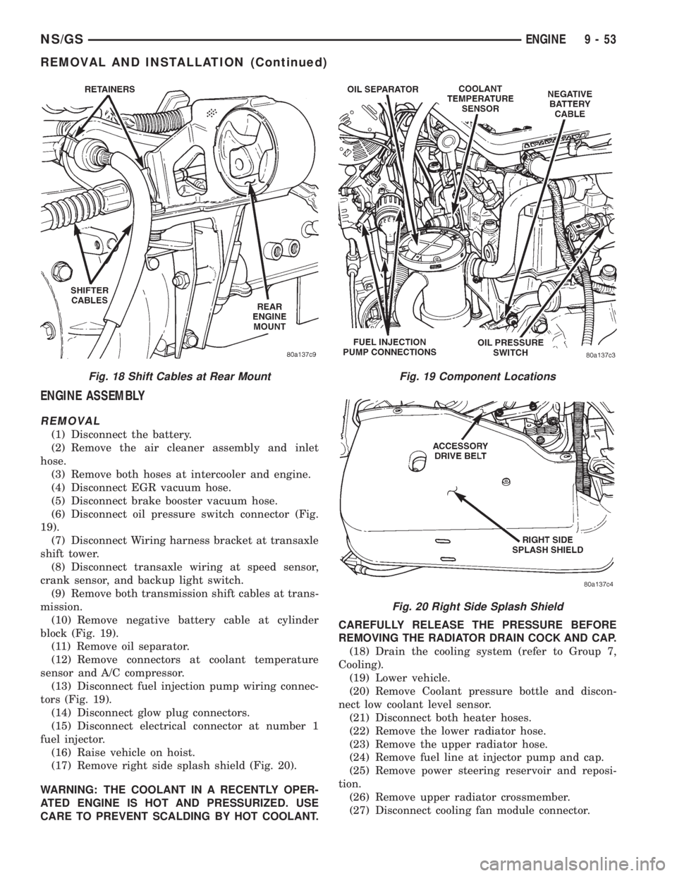
(6) Disconnect oil pressure switch connector (Fig.
19).
(7) Disconnect Wiring harness bracket at transaxle
shift tower.
(8) Disconnect transaxle wiring at speed sensor,
crank sensor, and backup light switch.
(9) Remove both transmission shift cables at trans-
mission.
(10) Remove negative battery cable at cylinder
block (Fig. 19).
(11) Remove oil separator.
(12) Remove connectors at coolant temperature
sensor and A/C compressor.
(13) Disconnect fuel injection pump wiring connec-
tors (Fig. 19).
(14) Disconnect glow plug connectors.
(15) Disconnect electrical connector at number 1
fuel injector.
(16) Raise vehicle on hoist.
(17) Remove right side splash shield (Fig. 20).
WARNING: THE COOLANT IN A RECENTLY OPER-
ATED ENGINE IS HOT AND PRESSURIZED. USE
CARE TO PREVENT SCALDING BY HOT COOLANT.CAREFULLY RELEASE THE PRESSURE BEFORE
REMOVING THE RADIATOR DRAIN COCK AND CAP.
(18) Drain the cooling system (refer to Group 7,
Cooling).
(19) Lower vehicle.
(20) Remove Coolant pressure bottle and discon-
nect low coolant level sensor.
(21) Disconnect both heater hoses.
(22) Remove the lower radiator hose.
(23) Remove the upper radiator hose.
(24) Remove fuel line at injector pump and cap.
(25) Remove power steering reservoir and reposi-
tion.
(26) Remove upper radiator crossmember.
(27) Disconnect cooling fan module connector.
Fig. 18 Shift Cables at Rear MountFig. 19 Component Locations
Fig. 20 Right Side Splash Shield
NS/GSENGINE 9 - 53
REMOVAL AND INSTALLATION (Continued)
Page 1232 of 1938
(28) Remove radiator support bolts.It is neces-
sary to loosen the receiver/dryer to gain access
to the radiator bolts.
(29) Remove radiator and fans as an assembly.
(30) Remove accessory drive belt generator/power
steering. Refer to Group 7, for procedure.
(31) Remove both power steering lines at pump,
and cap both lines.
NOTE: It is not necessary to discharge A/C system
for engine removal.
(32) Remove A/C compressor. Secure compressor
away from engine for clearance during engine
removal.
(33) Remove Generator and adjusting bracket.
NOTE: Do not remove the mounting base from the
generator. It is aligned at the factory and cannot be
realigned in the field.
(34) Hoist vehicle.
(35) Remove exhaust pipe at turbo outlet.
(36) Remove connections at starter.
(37) Remove power steering high pressure line
bracket at rear of oil pan.
(38) Remove both driveshafts from transaxle. Refer
to Group 2, Suspension and Driveshafts.
(39) Disconnect clutch cable at transaxle.
(40) Remove reinforcement plate on lower cross-
member.
(41) Remove front and rear engine mounts. Refer
to procedure outlined in this section.
(42) Drain engine oil and remove oil filter if neces-
sary.
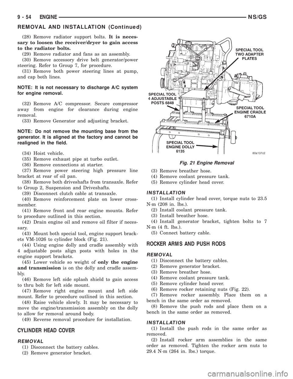
(43) Mount both special tool, engine support brack-
ets VM-1026 to cylinder block (Fig. 21).
(44) Using engine dolly and cradle assembly with
4 adjustable posts align posts with holes in the
engine support brackets.
(45) Lower vehicle so weight ofonly the engine
and transmissionis on the dolly and cradle assem-
bly.
(46) Remove left side splash shield to gain access
to thru bolt for left side mount.
(47) Remove right engine mount and left side
mount. Refer to procedure outlined in this section.
(48) Raise vehicle slowly. It may be necessary to
move the engine/transmission assembly on the dolly
to allow for removal around body.
(49) Reverse removal procedure for installation.
CYLINDER HEAD COVER
REMOVAL
(1) Disconnect the battery cables.
(2) Remove generator bracket.(3) Remove breather hose.
(4) Remove coolant pressure tank.
(5) Remove cylinder head cover.
INSTALLATION
(1) Install cylinder head cover, torque nuts to 23.5
N´m (208 in. lbs.).
(2) Install coolant pressure tank.
(3) Install breather hose.
(4) Install generator bracket, tighten bolts to 7
N´m (4 ft. lbs.).
(5) Connect battery cable.
ROCKER ARMS AND PUSH RODS
REMOVAL
(1) Disconnect the battery cables.
(2) Remove generator bracket.
(3) Remove breather hose.
(4) Remove coolant pressure tank.
(5) Remove cylinder head cover.
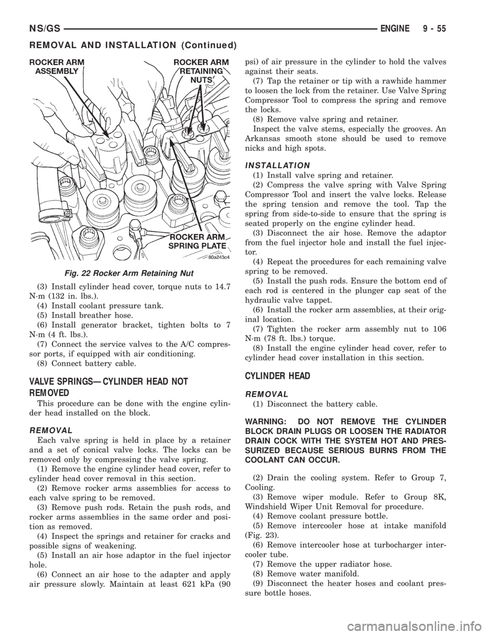
(6) Remove rocker retaining nuts (Fig. 22).
(7) Remove rocker assembly. Place them on a
bench in the same order as removed.
(8) Remove the push rods and place them on a
bench in the same order as removed.
INSTALLATION
(1) Install the push rods in the same order as
removed.
(2) Install rocker arm assemblies in the same
order as removed. Tighten the rocker arm nuts to
29.4 N´m (264 in. lbs.) torque.
Fig. 21 Engine Removal
9 - 54 ENGINENS/GS
REMOVAL AND INSTALLATION (Continued)
Page 1233 of 1938
(3) Install cylinder head cover, torque nuts to 14.7
N´m (132 in. lbs.).
(4) Install coolant pressure tank.
(5) Install breather hose.
(6) Install generator bracket, tighten bolts to 7
N´m (4 ft. lbs.).
(7) Connect the service valves to the A/C compres-
sor ports, if equipped with air conditioning.
(8) Connect battery cable.
VALVE SPRINGSÐCYLINDER HEAD NOT
REMOVED
This procedure can be done with the engine cylin-
der head installed on the block.
REMOVAL
Each valve spring is held in place by a retainer
and a set of conical valve locks. The locks can be
removed only by compressing the valve spring.
(1) Remove the engine cylinder head cover, refer to
cylinder head cover removal in this section.
(2) Remove rocker arms assemblies for access to
each valve spring to be removed.
(3) Remove push rods. Retain the push rods, and
rocker arms assemblies in the same order and posi-
tion as removed.
(4) Inspect the springs and retainer for cracks and
possible signs of weakening.
(5) Install an air hose adaptor in the fuel injector
hole.
(6) Connect an air hose to the adapter and apply
air pressure slowly. Maintain at least 621 kPa (90psi) of air pressure in the cylinder to hold the valves
against their seats.
(7) Tap the retainer or tip with a rawhide hammer
to loosen the lock from the retainer. Use Valve Spring
Compressor Tool to compress the spring and remove
the locks.
(8) Remove valve spring and retainer.
Inspect the valve stems, especially the grooves. An
Arkansas smooth stone should be used to remove
nicks and high spots.
INSTALLATION
(1) Install valve spring and retainer.
(2) Compress the valve spring with Valve Spring
Compressor Tool and insert the valve locks. Release
the spring tension and remove the tool. Tap the
spring from side-to-side to ensure that the spring is
seated properly on the engine cylinder head.
(3) Disconnect the air hose. Remove the adaptor
from the fuel injector hole and install the fuel injec-
tor.
(4) Repeat the procedures for each remaining valve
spring to be removed.
(5) Install the push rods. Ensure the bottom end of
each rod is centered in the plunger cap seat of the
hydraulic valve tappet.
(6) Install the rocker arm assemblies, at their orig-
inal location.
(7) Tighten the rocker arm assembly nut to 106
N´m (78 ft. lbs.) torque.
(8) Install the engine cylinder head cover, refer to
cylinder head cover installation in this section.
CYLINDER HEAD
REMOVAL
(1) Disconnect the battery cable.
WARNING: DO NOT REMOVE THE CYLINDER
BLOCK DRAIN PLUGS OR LOOSEN THE RADIATOR
DRAIN COCK WITH THE SYSTEM HOT AND PRES-
SURIZED BECAUSE SERIOUS BURNS FROM THE
COOLANT CAN OCCUR.
(2) Drain the cooling system. Refer to Group 7,
Cooling.
(3) Remove wiper module. Refer to Group 8K,
Windshield Wiper Unit Removal for procedure.
(4) Remove coolant pressure bottle.
(5) Remove intercooler hose at intake manifold
(Fig. 23).
(6) Remove intercooler hose at turbocharger inter-
cooler tube.
(7) Remove the upper radiator hose.
(8) Remove water manifold.
(9) Disconnect the heater hoses and coolant pres-
sure bottle hoses.
Fig. 22 Rocker Arm Retaining Nut
NS/GSENGINE 9 - 55
REMOVAL AND INSTALLATION (Continued)
Page 1234 of 1938
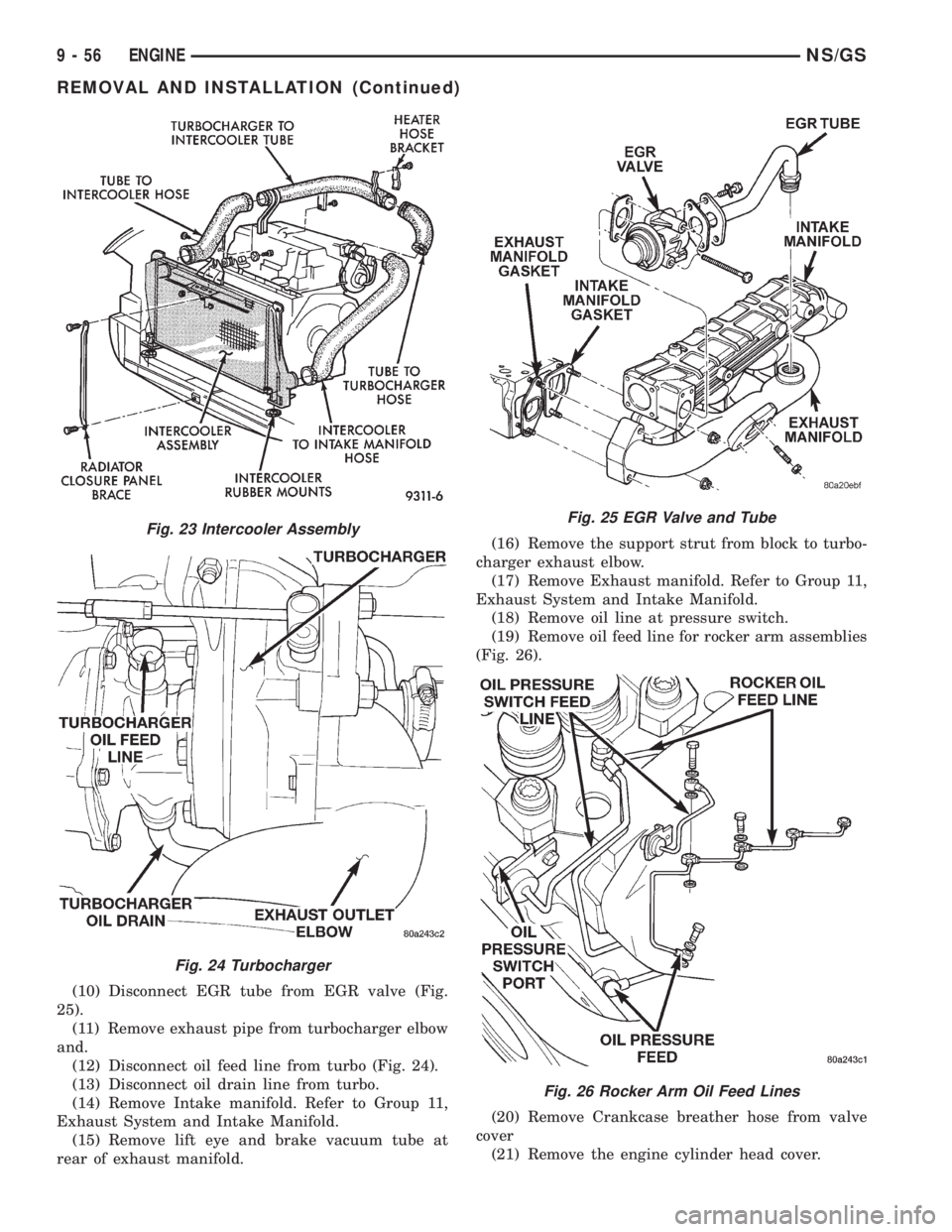
(10) Disconnect EGR tube from EGR valve (Fig.
25).
(11) Remove exhaust pipe from turbocharger elbow
and.
(12) Disconnect oil feed line from turbo (Fig. 24).
(13) Disconnect oil drain line from turbo.
(14) Remove Intake manifold. Refer to Group 11,
Exhaust System and Intake Manifold.
(15) Remove lift eye and brake vacuum tube at
rear of exhaust manifold.(16) Remove the support strut from block to turbo-
charger exhaust elbow.
(17) Remove Exhaust manifold. Refer to Group 11,
Exhaust System and Intake Manifold.
(18) Remove oil line at pressure switch.
(19) Remove oil feed line for rocker arm assemblies
(Fig. 26).
(20) Remove Crankcase breather hose from valve
cover
(21) Remove the engine cylinder head cover.
Fig. 23 Intercooler Assembly
Fig. 24 Turbocharger
Fig. 25 EGR Valve and Tube
Fig. 26 Rocker Arm Oil Feed Lines
9 - 56 ENGINENS/GS
REMOVAL AND INSTALLATION (Continued)
Page 1235 of 1938
(22) Remove the injector sensor wire at the con-
nector, and glow plug Connectors.
NOTE: The attachment point for the injector sensor
wire at the injector is not a connector. The connec-
tor is located in the wire 4 to 6 inches away from
the injector.
(23) Remove injector fuel lines from injectors to
pump.
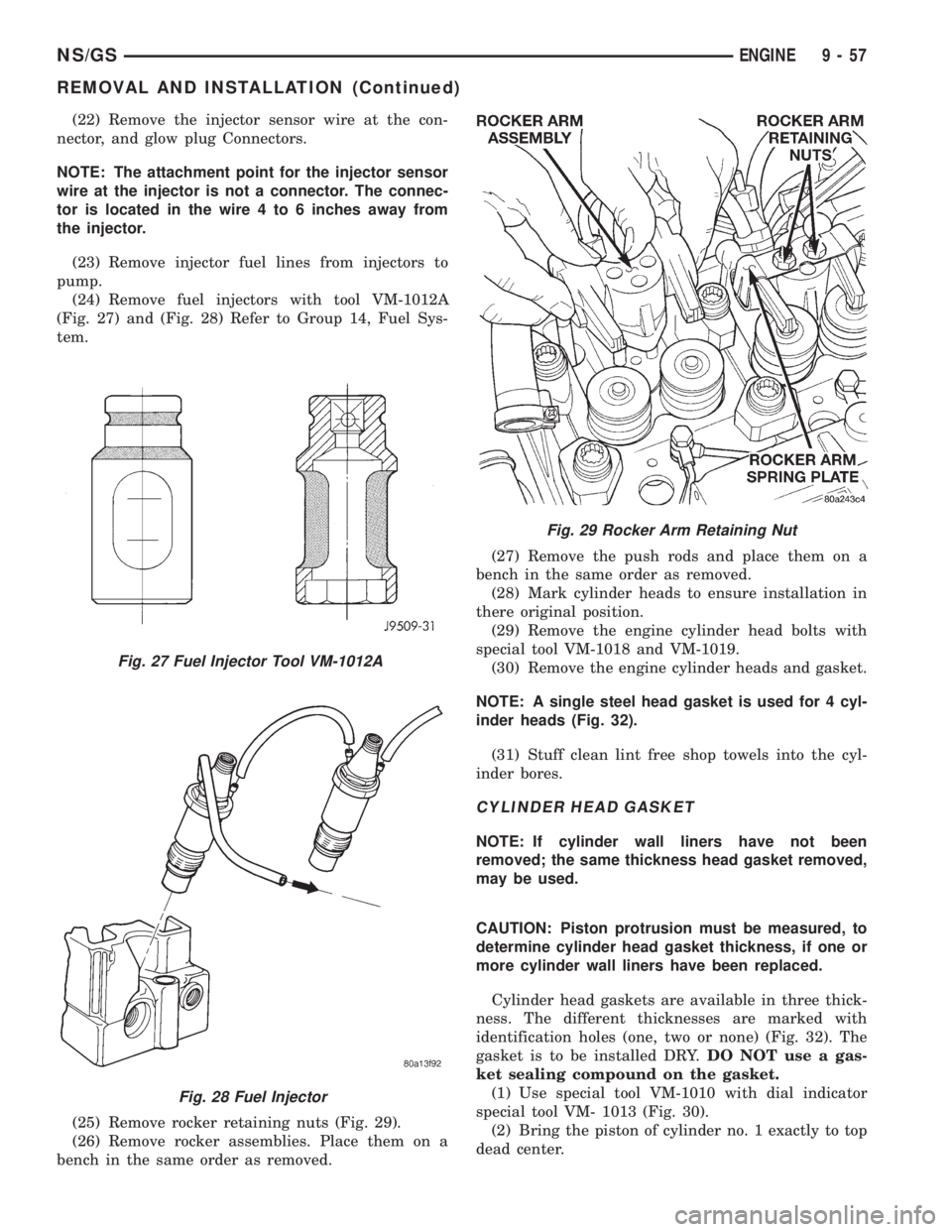
(24) Remove fuel injectors with tool VM-1012A
(Fig. 27) and (Fig. 28) Refer to Group 14, Fuel Sys-
tem.
(25) Remove rocker retaining nuts (Fig. 29).
(26) Remove rocker assemblies. Place them on a
bench in the same order as removed.(27) Remove the push rods and place them on a
bench in the same order as removed.
(28) Mark cylinder heads to ensure installation in
there original position.
(29) Remove the engine cylinder head bolts with
special tool VM-1018 and VM-1019.
(30) Remove the engine cylinder heads and gasket.
NOTE: A single steel head gasket is used for 4 cyl-
inder heads (Fig. 32).
(31) Stuff clean lint free shop towels into the cyl-
inder bores.
CYLINDER HEAD GASKET
NOTE: If cylinder wall liners have not been
removed; the same thickness head gasket removed,
may be used.
CAUTION: Piston protrusion must be measured, to
determine cylinder head gasket thickness, if one or
more cylinder wall liners have been replaced.
Cylinder head gaskets are available in three thick-
ness. The different thicknesses are marked with
identification holes (one, two or none) (Fig. 32). The
gasket is to be installed DRY.DO NOT use a gas-
ket sealing compound on the gasket.
(1) Use special tool VM-1010 with dial indicator
special tool VM- 1013 (Fig. 30).
(2) Bring the piston of cylinder no. 1 exactly to top
dead center.
Fig. 27 Fuel Injector Tool VM-1012A
Fig. 28 Fuel Injector
Fig. 29 Rocker Arm Retaining Nut
NS/GSENGINE 9 - 57
REMOVAL AND INSTALLATION (Continued)