1996 CHRYSLER VOYAGER engine
[x] Cancel search: enginePage 1212 of 1938
CYLINDER BLOCK AND BORE
(1) Clean cylinder block thoroughly and check all
core hole plugs for evidence of leaking.
(2) If new core plugs are installed, Refer to Engine
Core Plugs outlined in this section.
(3) Examine block and cylinder bores for cracks or
fractures.
CYLINDER BORE INSPECTION
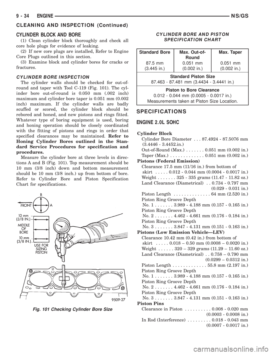
The cylinder walls should be checked for out-of-
round and taper with Tool C-119 (Fig. 101). The cyl-
inder bore out-of-round is 0.050 mm (.002 inch)
maximum and cylinder bore taper is 0.051 mm (0.002
inch) maximum. If the cylinder walls are badly
scuffed or scored, the cylinder block should be
rebored and honed, and new pistons and rings fitted.
Whatever type of boring equipment is used, boring
and honing operation should be closely coordinated
with the fitting of pistons and rings in order that
specified clearances may be maintained.Refer to
Honing Cylinder Bores outlined in the Stan-
dard Service Procedures for specification and
procedures.
Measure the cylinder bore at three levels in direc-
tions A and B (Fig. 101). Top measurement should be
10 mm (3/8 inch) down and bottom measurement
should be 10 mm (3/8 inch.) up from bottom of bore.
Refer to Cylinder Bore and Piston Specification
Chart for specifications.
SPECIFICATIONS
ENGINE 2.0L SOHC
Cylinder Block
Cylinder Bore Diameter . . . 87.4924 - 87.5076 mm
(3.4446 - 3.4452.in.)
Out-of-Round (Max.).......0.051 mm (0.002 in.)
Taper (Max.).............0.051 mm (0.002 in.)
Pistons (Federal Emission)
Clearance 17.5 mm (11/16 in.) from bottom of
skirt.....0.012 - 0.044 mm (0.0004 - 0.0017 in.)
Weight.......325-335grams (11.47 - 11.82 oz.)
Land Clearance (Diametrical) . . 0.734 - 0.797 mm
(0.029 - 0.031 in.)
Piston Length..............64mm(2.520 in.)
Piston Ring Groove Depth
No.1.......3.989 - 4.188 mm (0.157 - 0.165 in.)
Piston Ring Groove Depth
No.2.......4.462 - 4.661 mm (0.176 - 0.184 in.)
Piston Ring Groove Depth
No.3.......3.847 - 4.131 mm (0.151 - 0.163 in.)
Pistons (Low Emission VehicleÐLEV)
Clearance 10.42 mm (0.42 in.) from bottom of
skirt.....0.018 ± 0.50 mm (0.0008 ± 0.0020 in.)
Weight......320±329grams (11.29 ± 11.60 oz.)
Land Clearance (Diametrical) . . 0.758 ± 0.790 mm
(0.0299 ± 0.0312 in.)
Piston Length.............55.8 mm (2.197 in.)
Piston Ring Groove Depth
No.1.......3.989 - 4.188 mm (0.157 - 0.165 in.)
Piston Ring Groove Depth
No.2.......4.462 - 4.661 mm (0.176 - 0.184 in.)
Piston Ring Groove Depth
No.3.......3.847 - 4.131 mm (0.151 - 0.163 in.)
Piston Pins
Clearance in Piston..........0.008 - 0.020 mm
(0.0003 - 0.0008 in.)
In Rod (Interference).........0.018 - 0.043 mm
(0.0007 - 0.0017 in.)
Fig. 101 Checking Cylinder Bore Size
CYLINDER BORE AND PISTON
SPECIFICATION CHART
Standard Bore Max. Out-of-
RoundMax. Taper
87.5 mm
(3.445 in.)0.051 mm
(0.002 in.)0.051 mm
(0.002 in.)
Standard Piston Size
87.463 - 87.481 mm (3.4434 - 3.4441 in.)
Piston to Bore Clearance
0.012 - 0.044 mm (0.0005 - 0.0017 in.)
Measurements taken at Piston Size Location.
9 - 34 ENGINENS/GS
CLEANING AND INSPECTION (Continued)
Page 1213 of 1938
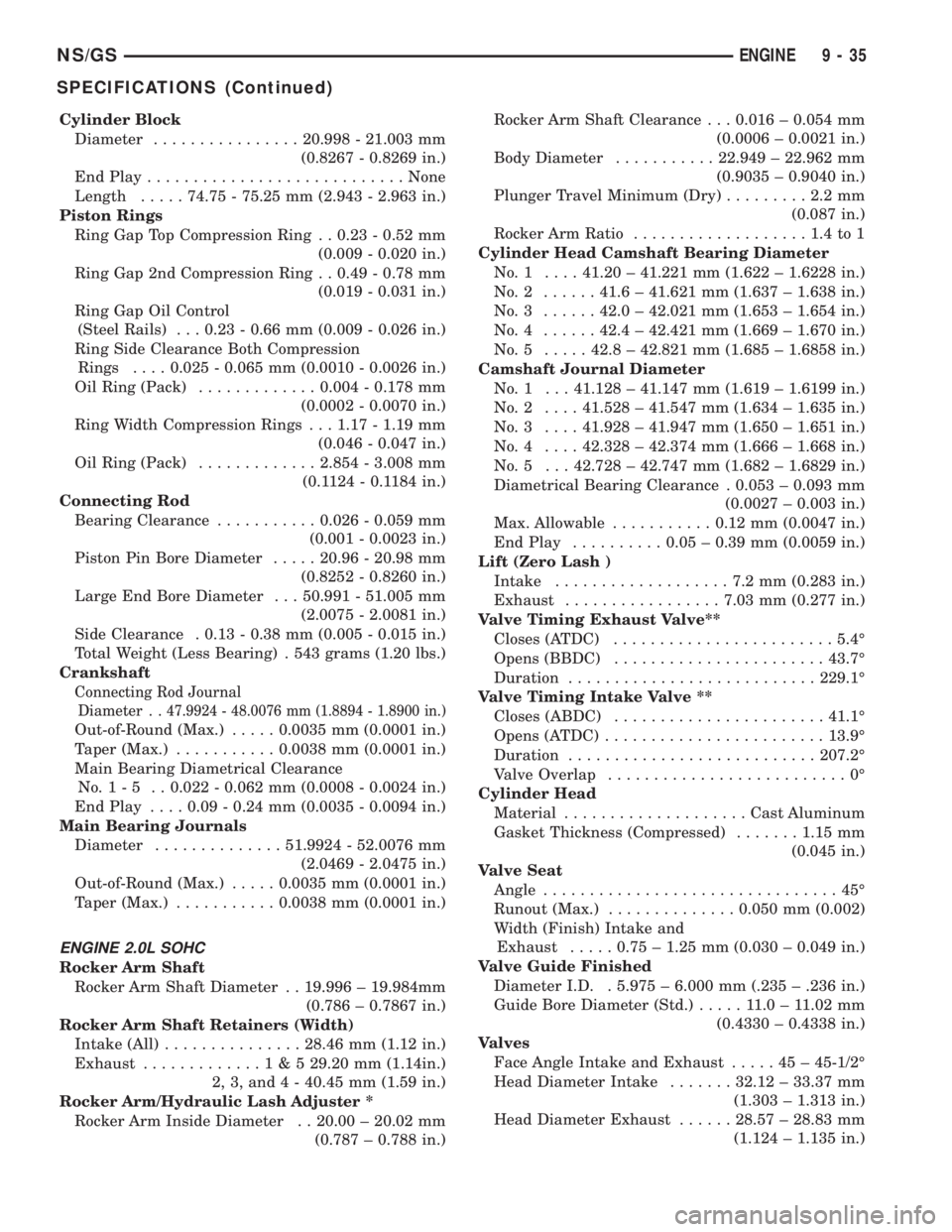
Cylinder Block
Diameter................20.998 - 21.003 mm
(0.8267 - 0.8269 in.)
End Play............................None
Length.....74.75 - 75.25 mm (2.943 - 2.963 in.)
Piston Rings
Ring Gap Top Compression Ring . . 0.23 - 0.52 mm
(0.009 - 0.020 in.)
Ring Gap 2nd Compression Ring . . 0.49 - 0.78 mm
(0.019 - 0.031 in.)
Ring Gap Oil Control
(Steel Rails) . . . 0.23 - 0.66 mm (0.009 - 0.026 in.)
Ring Side Clearance Both Compression
Rings....0.025 - 0.065 mm (0.0010 - 0.0026 in.)
Oil Ring (Pack).............0.004 - 0.178 mm
(0.0002 - 0.0070 in.)
Ring Width Compression Rings . . . 1.17 - 1.19 mm
(0.046 - 0.047 in.)
Oil Ring (Pack).............2.854 - 3.008 mm
(0.1124 - 0.1184 in.)
Connecting Rod
Bearing Clearance...........0.026 - 0.059 mm
(0.001 - 0.0023 in.)
Piston Pin Bore Diameter.....20.96 - 20.98 mm
(0.8252 - 0.8260 in.)
Large End Bore Diameter . . . 50.991 - 51.005 mm
(2.0075 - 2.0081 in.)
Side Clearance . 0.13 - 0.38 mm (0.005 - 0.015 in.)
Total Weight (Less Bearing) . 543 grams (1.20 lbs.)
Crankshaft
Connecting Rod Journal
Diameter . .
47.9924 - 48.0076 mm (1.8894 - 1.8900 in.)
Out-of-Round (Max.).....0.0035 mm (0.0001 in.)
Taper (Max.)...........0.0038 mm (0.0001 in.)
Main Bearing Diametrical Clearance
No.1-5 ..0.022 - 0.062 mm (0.0008 - 0.0024 in.)
End Play....0.09 - 0.24 mm (0.0035 - 0.0094 in.)
Main Bearing Journals
Diameter..............51.9924 - 52.0076 mm
(2.0469 - 2.0475 in.)
Out-of-Round (Max.).....0.0035 mm (0.0001 in.)
Taper (Max.)...........0.0038 mm (0.0001 in.)
ENGINE 2.0L SOHC
Rocker Arm Shaft
Rocker Arm Shaft Diameter . . 19.996 ± 19.984mm
(0.786 ± 0.7867 in.)
Rocker Arm Shaft Retainers (Width)
Intake (All)...............28.46 mm (1.12 in.)
Exhaust.............1&529.20 mm (1.14in.)
2, 3, and 4 - 40.45 mm (1.59 in.)
Rocker Arm/Hydraulic Lash Adjuster *
Rocker Arm Inside Diameter . . 20.00 ± 20.02 mm
(0.787 ± 0.788 in.)Rocker Arm Shaft Clearance . . . 0.016 ± 0.054 mm
(0.0006 ± 0.0021 in.)
Body Diameter...........22.949 ± 22.962 mm
(0.9035 ± 0.9040 in.)
Plunger Travel Minimum (Dry).........2.2mm
(0.087 in.)
Rocker Arm Ratio...................1.4to1
Cylinder Head Camshaft Bearing Diameter
No.1 ....41.20 ± 41.221 mm (1.622 ± 1.6228 in.)
No.2 ......41.6 ± 41.621 mm (1.637 ± 1.638 in.)
No.3 ......42.0 ± 42.021 mm (1.653 ± 1.654 in.)
No.4 ......42.4 ± 42.421 mm (1.669 ± 1.670 in.)
No.5 .....42.8 ± 42.821 mm (1.685 ± 1.6858 in.)
Camshaft Journal Diameter
No. 1 . . . 41.128 ± 41.147 mm (1.619 ± 1.6199 in.)
No.2 ....41.528 ± 41.547 mm (1.634 ± 1.635 in.)
No.3 ....41.928 ± 41.947 mm (1.650 ± 1.651 in.)
No.4 ....42.328 ± 42.374 mm (1.666 ± 1.668 in.)
No. 5 . . . 42.728 ± 42.747 mm (1.682 ± 1.6829 in.)
Diametrical Bearing Clearance . 0.053 ± 0.093 mm
(0.0027 ± 0.003 in.)
Max. Allowable...........0.12 mm (0.0047 in.)
End Play..........0.05 ± 0.39 mm (0.0059 in.)
Lift (Zero Lash )
Intake...................7.2mm(0.283 in.)
Exhaust.................7.03 mm (0.277 in.)
Valve Timing Exhaust Valve**
Closes (ATDC)........................5.4É
Opens (BBDC).......................43.7É
Duration...........................229.1É
Valve Timing Intake Valve **
Closes (ABDC).......................41.1É
Opens (ATDC)........................13.9É
Duration...........................207.2É
Valve Overlap..........................0É
Cylinder Head
Material....................Cast Aluminum
Gasket Thickness (Compressed).......1.15 mm
(0.045 in.)
Valve Seat
Angle................................45É
Runout (Max.)..............0.050 mm (0.002)
Width (Finish) Intake and
Exhaust.....0.75 ± 1.25 mm (0.030 ± 0.049 in.)
Valve Guide Finished
Diameter I.D. . 5.975 ± 6.000 mm (.235 ± .236 in.)
Guide Bore Diameter (Std.).....11.0±11.02 mm
(0.4330 ± 0.4338 in.)
Valves
Face Angle Intake and Exhaust.....45±45-1/2É
Head Diameter Intake.......32.12 ± 33.37 mm
(1.303 ± 1.313 in.)
Head Diameter Exhaust......28.57 ± 28.83 mm
(1.124 ± 1.135 in.)
NS/GSENGINE 9 - 35
SPECIFICATIONS (Continued)
Page 1214 of 1938
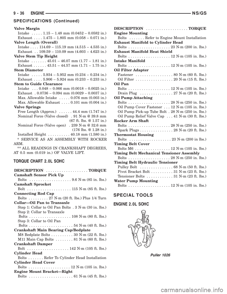
Valve Margin
Intake.....1.15 ± 1.48 mm (0.0452 ± 0.0582 in.)
Exhaust....1.475 ± 1.805 mm (0.058 ± 0.071 in.)
Valve Length (Overall)
Intake....114.69 ± 115.19 mm (4.515 ± 4.535 in.)
Exhaust . . 109.59 ± 110.09 mm (4.603 ± 4.623 in.)
Valve Stem Tip Height
Intake.......45.01 ± 46.07 mm (1.77 ± 1.81 in.)
Exhaust......43.51 ± 44.57 mm (1.71 ± 1.75 in.)
Stem Diameter
Intake.....5.934 ± 5.952 mm (0.234 ± 0.234 in.)
Exhaust....5.906 ± 5.924 mm (0.233 ± 0.233 in.)
Stem to Guide Clearance
Intake . . . 0.048 ± 0.066 mm (0.0018 ± 0.0025 in.)
Exhaust . 0.0736 ± 0.094 mm (0.0029 ± 0.0037 in.)
Max. Allowable Intake.....0.076 mm (0.003 in.)
Max. Allowable Exhaust....0.101 mm (0.004 in.)
Valve Springs
Free Length (Approx.)......44.4 mm (1.747 in.)
Nominal Force (Valve closed) . 91 N´m @ 39.8 mm
(67 ft. lbs. @ 1.57 in.)
Nominal Force (Valve open) . 239 N´m @ 32.6 mm
(176 lbs. @ 1.28 in.)
Installed Height..........40.18 mm (1.580 in.)
* SERVICE AS AN ASSEMBLY WITH ROCKER
ARM.
** ALL READINGS IN CRANKSHAFT DEGREES,
AT 0.5 mm (0.019 in.) OF VALVE LIFT.
TORQUE CHART 2.0L SOHC
DESCRIPTION...................TORQUE
Camshaft Sensor Pick Up
Bolts...................9.6N´m(85in.lbs.)
Camshaft Sprocket
Bolt....................115N´m(85ft.lbs.)
Connecting Rod Cap
Bolts.........27N´m(20ft.lbs.) Plus 1/4 Turn
CollarÐOil Pan to Transaxle
Step 1: Collar to Oil Pan Bolts . 3 N´m (30 in. lbs.)
Step 2: Collar to Transaxle
Bolts...................108N´m(80ft.lbs.)
Step 3: Collar to Oil Pan
Bolts....................54N´m(40ft.lbs.)
Crankshaft Main Bearing Cap/Bedplate
M8 Bedplate Bolts..........30N´m(22ft.lbs.)
M11 Main Cap Bolts........81N´m(60ft.lbs.)
Crankshaft Damper
Bolt...................142N´m(105 ft. lbs.)
Cylinder Head
Bolts.......Refer To Cylinder Head Installation
Cylinder Head Cover
Bolts...................12N´m(105 in. lbs.)
Engine Mount BracketÐRight
Bolts....................61N´m(45ft.lbs.)DESCRIPTION...................TORQUE
Engine Mounting
Bolts.......Refer to Engine Mount Installation
Exhaust Manifold to Cylinder Head
Bolts...................23N´m(200 in. lbs.)
Exhaust Manifold Heat Shield
Bolts...................12N´m(105 in. lbs.)
Intake Manifold
Bolts...................12N´m(105 in. lbs.)
Oil Filter Adapter
Fastener.................80N´m(60ft.lbs.)
Oil Filter.................20N´m(15ft.lbs.)
Oil Pan
Bolts...................12N´m(105 in. lbs.)
Drain Plug...............27N´m(20ft.lbs.)
Oil Pump Attaching
Bolts...................28N´m(250 in. lbs.)
Oil Pump Cover Fastener . . . 12 N´m (105 in. lbs.)
Oil Pump Pick-up Tube Bolt . 28 N´m (250 in. lbs.)
Oil Pump Relief Valve Cap . . . 41 N´m (30 ft. lbs.)
Rocker Arm Shaft
Bolts...................28N´m(250 in. lbs.)
Spark Plugs...............28N´m(20ft.lbs.)
Thermostat Housing
Bolts...................23N´m(200 in lbs.)
Timing Belt Cover
Bolts M6................12N´m(105 in. lbs.)
Timing Belt Mechanical Tensioner Assembly
Bolts...................28N´m(250 in. lbs.)
Timing Belt Hydraulic Tensioner
Pulley Bolt...............68N´m(50ft.lbs.)
Pivot Bracket Bolt..........31N´m(23ft.lbs.)
Tensioner Bolts............31N´m(23ft.lbs.)
Water Pump Mounting
Bolts...................12N´m(105 in. lbs.)
SPECIAL TOOLS
ENGINE 2.0L SOHC
Puller 1026
9 - 36 ENGINENS/GS
SPECIFICATIONS (Continued)
Page 1215 of 1938
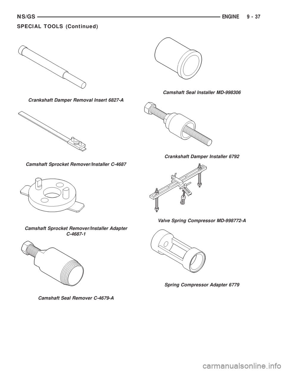
Crankshaft Damper Removal Insert 6827-A
Camshaft Sprocket Remover/Installer C-4687
Camshaft Sprocket Remover/Installer Adapter
C-4687-1
Camshaft Seal Remover C-4679-A
Camshaft Seal Installer MD-998306
Crankshaft Damper Installer 6792
Valve Spring Compressor MD-998772-A
Spring Compressor Adapter 6779
NS/GSENGINE 9 - 37
SPECIAL TOOLS (Continued)
Page 1216 of 1938
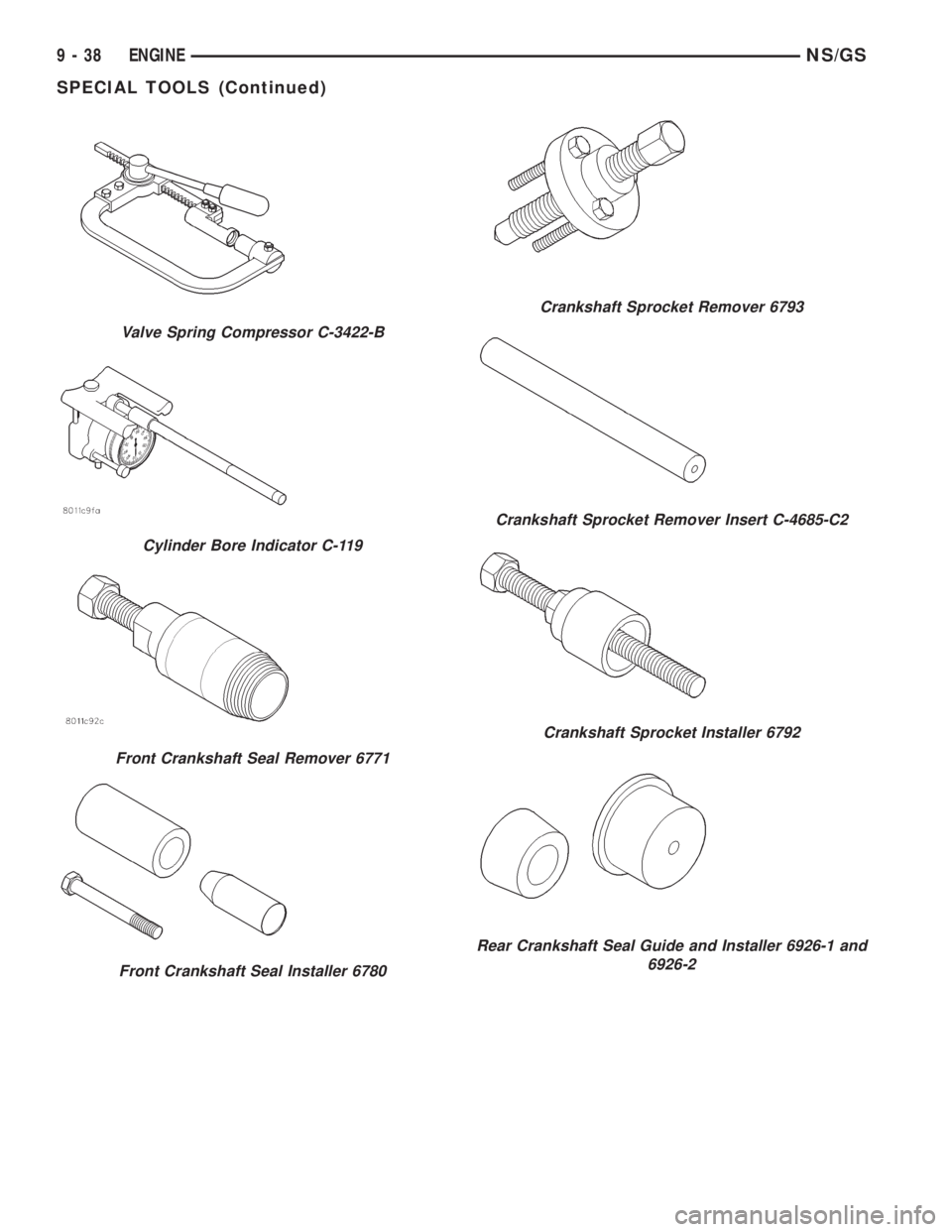
Valve Spring Compressor C-3422-B
Cylinder Bore Indicator C-119
Front Crankshaft Seal Remover 6771
Front Crankshaft Seal Installer 6780
Crankshaft Sprocket Remover 6793
Crankshaft Sprocket Remover Insert C-4685-C2
Crankshaft Sprocket Installer 6792
Rear Crankshaft Seal Guide and Installer 6926-1 and
6926-2
9 - 38 ENGINENS/GS
SPECIAL TOOLS (Continued)
Page 1217 of 1938
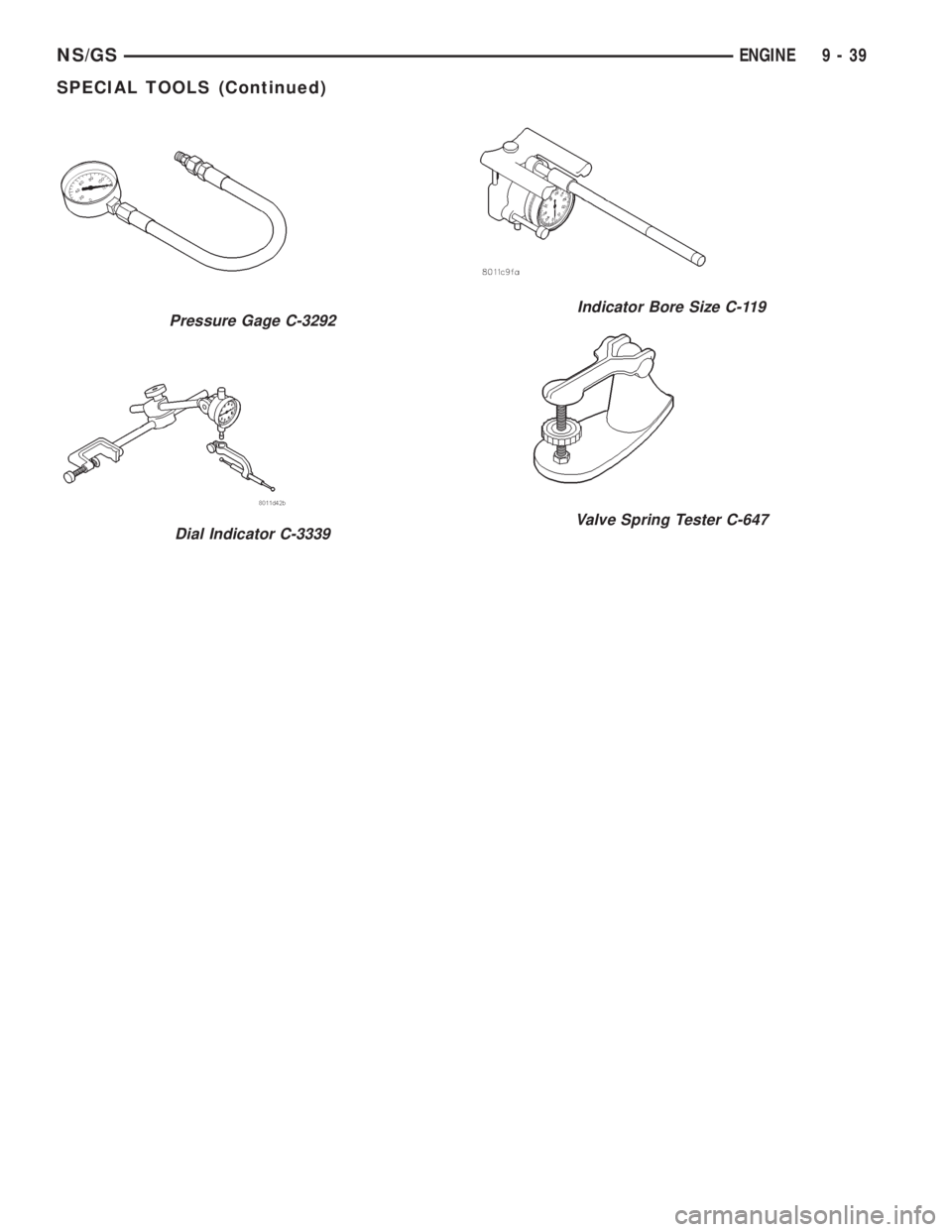
Pressure Gage C-3292
Dial Indicator C-3339
Indicator Bore Size C-119
Valve Spring Tester C-647
NS/GSENGINE 9 - 39
SPECIAL TOOLS (Continued)
Page 1218 of 1938
2.5L VM DIESEL
INDEX
page page
GENERAL INFORMATION
ENGINE IDENTIFICATION................ 41
GENERAL SPECIFICATION............... 40
DESCRIPTION AND OPERATION
LUBRICATION SYSTEM.................. 41
DIAGNOSIS AND TESTING
ENGINE DIAGNOSISÐMECHANICAL....... 44
ENGINE DIAGNOSISÐPERFORMANCE..... 43
HYDRAULIC TAPPETS................... 47
SERVICE PROCEDURES
CHANGING ENGINE OIL AND FILTER....... 47
CHECKING OIL LEVEL................... 47
CRANKSHAFT END PLAY................ 50
FITTING PISTON RING.................. 50
TIMING PROCEDURE................... 49
VALVE AND SEAT REFACING............. 49
REMOVAL AND INSTALLATION
CAMSHAFT........................... 62
CAMSHAFT BEARINGS.................. 63
CRANKSHAFT MAIN BEARINGS........... 63
CRANKSHAFTÐREMOVAL............... 72
CYLINDER HEAD....................... 55
CYLINDER HEAD COVER................ 54
CYLINDER LINER...................... 72
ENGINE ASSEMBLY..................... 53
ENGINE MOUNTÐFRONT................ 51
ENGINE MOUNTÐREAR................. 52
ENGINE MOUNTÐRIGHT................ 51
HYDRAULIC TAPPETS................... 60
INJECTION PUMP...................... 61
MOUNTÐLEFT SIDE.................... 51
OIL FILTER ADAPTER AND OIL COOLER.... 68
OILPAN .............................. 66OIL PUMP............................ 67
OIL PUMP PRESSURE RELIEF VALVE...... 67
PISTONS AND CONNECTING ROD......... 68
REAR CRANKSHAFT OIL SEAL............ 72
ROCKER ARMS AND PUSH RODS......... 54
TIMING GEAR COVER................... 61
TIMING GEAR COVER OIL SEAL........... 61
VACUUM PUMP........................ 68
VALVE SPRINGSÐCYLINDER HEAD NOT
REMOVED.......................... 55
VALVES AND VALVE SPRINGSÐHEAD OFF . . 60
VIBRATION DAMPER.................... 61
DISASSEMBLY AND ASSEMBLY
HYDRAULIC TAPPETS................... 73
CLEANING AND INSPECTION
CRANKSHAFT......................... 77
CRANKSHAFT MAIN BEARING............ 77
CYLINDER HEAD....................... 75
CYLINDER HEAD COVERS............... 74
CYLINDER LINER...................... 78
HYDRAULIC TAPPETS................... 76
OILPAN .............................. 78
OIL PUMP............................ 76
PISTON AND CONNECTING ROD.......... 76
ROCKER ARMS AND PUSH RODS......... 74
TIMING GEAR COVER................... 75
VALVES AND VALVE SPRINGS............ 76
SPECIFICATIONS
2.5L VM DIESEL........................ 78
TORQUE............................. 80
SPECIAL TOOLS
2.5L VM DIESEL........................ 81
GENERAL INFORMATION
GENERAL SPECIFICATION
Type ........................425CLIEE (36B)
Displacement...................2.5L (2499 cc)
Bore.............................92.00 mm
Stroke............................94.00 mm
Compression Ratio....................20.95:1
Vacuum at Idle..........600mm/Hg (23.6 In/Hg)
Thermostat Opening................80ÉC62ÉC
Generator Rating............Bosch 50/120 Amp
Cooling System Capacity..............9.5Liter
Power Steering Capacity.............0.75 LiterType ........................425CLIEE (36B)
Engine Oil Capacity.....6.5Liters With Oil Filter
Change
Timing System . Pushrod Operated Overhead valves,
With Gear-Driven Camshaft.
Air Intake........................DryFilter
Fuel Feed...........Vacuum Pump Incorporated
in Injection Pump.
Fuel System.............Indirect Fuel Injection
(Precombustion Chamber)
Combustion Cycle....................4Stroke
Cooling System..................Water Cooled
Injection Pump.......Rotary Pump Electronically
Controlled.
9 - 40 ENGINENS/GS
Page 1219 of 1938
Type ........................425CLIEE (36B)
Lubrication . Pressure Lubrication by Rotary Pump,
Full-Flow Filtration
Engine Rotation....Clockwise Viewed From Front
Cover
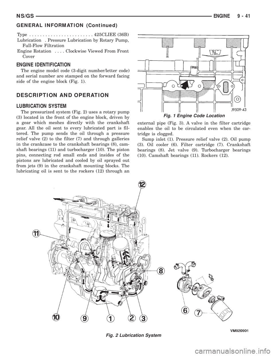
ENGINE IDENTIFICATION
The engine model code (3-digit number/letter code)
and serial number are stamped on the forward facing
side of the engine block (Fig. 1).
DESCRIPTION AND OPERATION
LUBRICATION SYSTEM
The pressurized system (Fig. 2) uses a rotary pump
(3) located in the front of the engine block, driven by
a gear which meshes directly with the crankshaft
gear. All the oil sent to every lubricated part is fil-
tered. The pump sends the oil through a pressure
relief valve (2) to the filter (7) and through galleries
in the crankcase to the crankshaft bearings (8), cam-
shaft bearings (11) and turbocharger (10). The piston
pins, connecting rod small ends and insides of the
pistons are lubricated and cooled by oil sprayed out
from jets (9) in the crankshaft mounting blocks. The
lubricating oil is sent to the rockers (12) through anexternal pipe (Fig. 3). A valve in the filter cartridge
enables the oil to be circulated even when the car-
tridge is clogged.
Sump inlet (1). Pressure relief valve (2). Oil pump
(3). Oil cooler (6). Filter cartridge (7). Crankshaft
bearings (8). Jet valve (9). Turbocharger bearings
(10). Camshaft bearings (11). Rockers (12).
Fig. 2 Lubrication System
Fig. 1 Engine Code Location
NS/GSENGINE 9 - 41
GENERAL INFORMATION (Continued)