Page 1260 of 1938
Crankshaft Remover/Installer Sleeve VM.1004
Torque Angle Gauge VM.1005
Cylinder Head Bolt Wrench VM.1006A
Cylinder Head Guide Studs VM.1009
Cylinder Liner Protrusion Tool VM.1010
Injector Socket Remover/Installer VM.1012A
9 - 82 ENGINENS/GS
SPECIAL TOOLS (Continued)
Page 1261 of 1938
Dial Indicator Gauge VM.1013
Flywheel Locking Tool VM.1014
Timing Cover Oil Seal Installer VM.1015
Cylinder Retainers VM.1016
Cylinder Head Bolt Wrench M12 VM.1018
NS/GSENGINE 9 - 83
SPECIAL TOOLS (Continued)
Page 1262 of 1938
Adapter Cylinder Leakage Tester VM.1021
Cylinder Head Bolt Wrench M14 VM.1019
Support Brackets Engine Removal/Installation
VM.1026
9 - 84 ENGINENS/GS
SPECIAL TOOLS (Continued)
Page 1263 of 1938
EXHAUST SYSTEM AND INTAKE MANIFOLD
CONTENTS
page page
GENERAL INFORMATION
CATALYTIC CONVERTERS................. 1
EXHAUST FLEX-JOINT COUPLING........... 2
EXHAUST GAS RECIRCULATION (EGR)....... 2
EXHAUST SYSTEM....................... 1
HEAT SHIELDS.......................... 2
DESCRIPTION AND OPERATION
INTAKE/EXHAUST MANIFOLDÐ2.4L ENGINE . . 3
INTAKE/EXHAUST MANIFOLDÐ3.0L ENGINE . . 3
INTAKE/EXHAUST MANIFOLDÐ3.3/3.8L
ENGINES............................. 3
DIAGNOSIS AND TESTING
EXHAUST SYSTEM....................... 3REMOVAL AND INSTALLATION
EXHAUST MANIFOLDÐ2.4L ENGINE........ 8
EXHAUST MANIFOLDÐ3.0L ENGINE....... 11
EXHAUST MANIFOLDSÐ3.3/3.8L ENGINE . . . 16
EXHAUST PIPES, MUFFLERS AND TAILPIPES . 4
INTAKE MANIFOLD LOWERÐ2.4L ENGINE.... 6
INTAKE MANIFOLDÐ3.0L ENGINE.......... 8
INTAKE MANIFOLDÐ3.3/3.8L ENGINE...... 12
UPPER INTAKE MANIFOLDÐ2.4L ENGINE.... 4
CLEANING AND INSPECTION
EXHAUST MANIFOLD.................... 17
INTAKE MANIFOLD...................... 17
SPECIFICATIONS
TORQUE CHART........................ 18
GENERAL INFORMATION
EXHAUST SYSTEM
The exhaust systems are produced in several con-
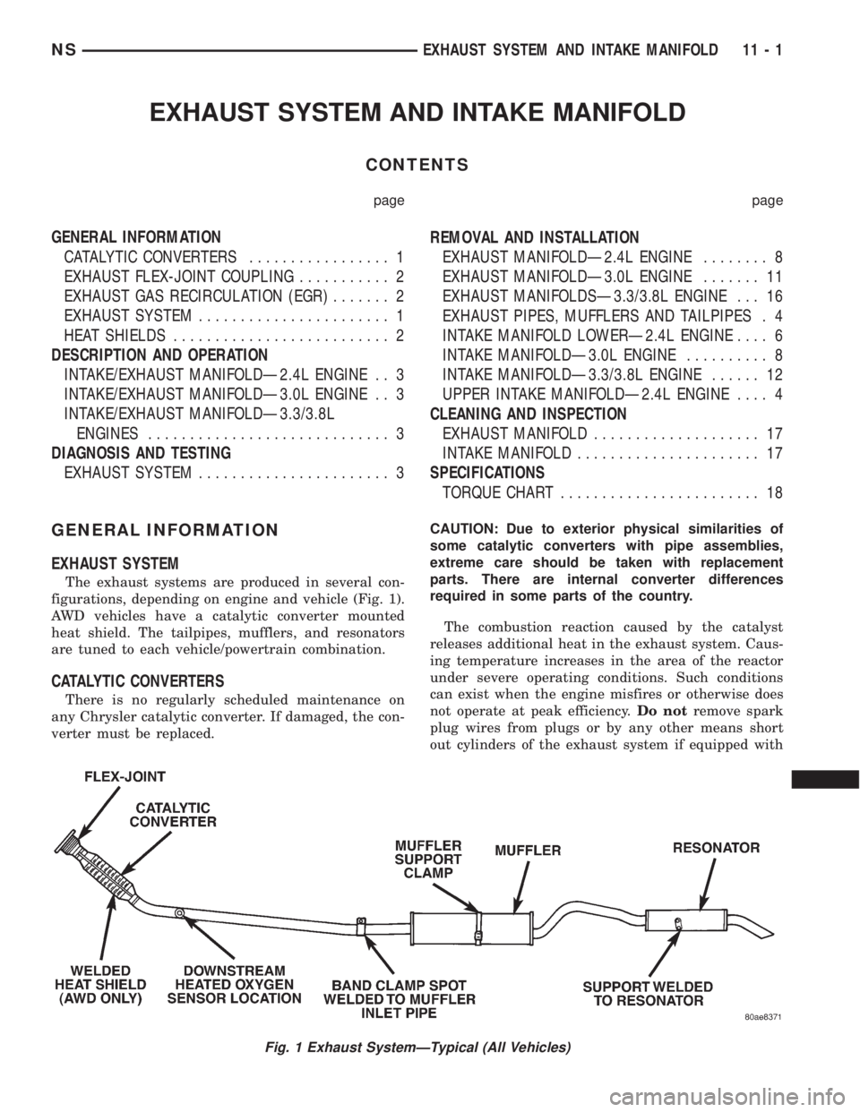
figurations, depending on engine and vehicle (Fig. 1).
AWD vehicles have a catalytic converter mounted
heat shield. The tailpipes, mufflers, and resonators
are tuned to each vehicle/powertrain combination.
CATALYTIC CONVERTERS
There is no regularly scheduled maintenance on
any Chrysler catalytic converter. If damaged, the con-
verter must be replaced.CAUTION: Due to exterior physical similarities of
some catalytic converters with pipe assemblies,
extreme care should be taken with replacement
parts. There are internal converter differences
required in some parts of the country.
The combustion reaction caused by the catalyst
releases additional heat in the exhaust system. Caus-
ing temperature increases in the area of the reactor
under severe operating conditions. Such conditions
can exist when the engine misfires or otherwise does
not operate at peak efficiency.Do notremove spark
plug wires from plugs or by any other means short
out cylinders of the exhaust system if equipped with
Fig. 1 Exhaust SystemÐTypical (All Vehicles)
NSEXHAUST SYSTEM AND INTAKE MANIFOLD 11 - 1
Page 1264 of 1938
a catalytic converter. Failure of the catalytic con-
verter can occur due to temperature increases caused
by unburned fuel igniting when passing through the
converter.
The use of the catalysts also involves some non-au-
tomotive problems. Unleaded gasoline must be used
to avoid poisoning the catalyst core. Do not allow
engine to operate at fast idle for extended periods
(over 5 minutes). This condition may result in exces-
sive exhaust system and floor pan temperatures.
EXHAUST GAS RECIRCULATION (EGR)
To assist in the control of oxides of nitrogen (NOx)
in engine exhaust, all engines are equipped with an
exhaust gas recirculation system. The use of exhaust
gas to dilute incoming air/fuel mixtures lowers peak
flame temperatures during combustion, thus limiting
the formation of NOx.
Exhaust gases are taken from opening in the
exhaust manifold passage to the intake manifold.
REFER TO SECTION 25 FOR A COMPLETE
DESCRIPTION, DIAGNOSIS AND SERVICE PRO-
CEDURES ON THE EXHAUST GAS RECIRCULA-
TION SYSTEM AND COMPONENTS.
HEAT SHIELDS
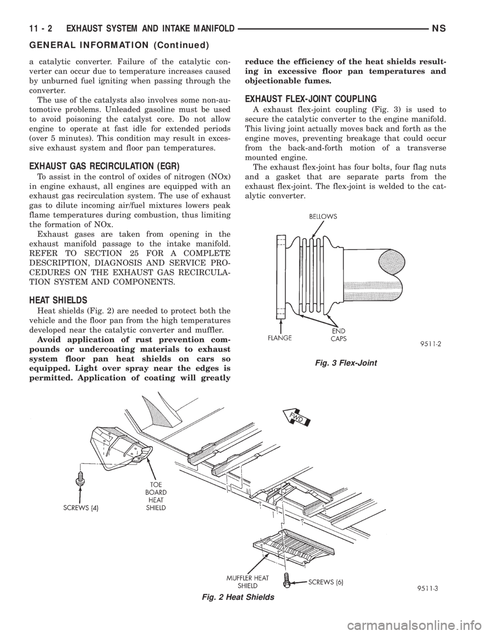
Heat shields (Fig. 2) are needed to protect both the
vehicle and the floor pan from the high temperatures
developed near the catalytic converter and muffler.
Avoid application of rust prevention com-
pounds or undercoating materials to exhaust
system floor pan heat shields on cars so
equipped. Light over spray near the edges is
permitted. Application of coating will greatlyreduce the efficiency of the heat shields result-
ing in excessive floor pan temperatures and
objectionable fumes.
EXHAUST FLEX-JOINT COUPLING
A exhaust flex-joint coupling (Fig. 3) is used to
secure the catalytic converter to the engine manifold.
This living joint actually moves back and forth as the
engine moves, preventing breakage that could occur
from the back-and-forth motion of a transverse
mounted engine.
The exhaust flex-joint has four bolts, four flag nuts
and a gasket that are separate parts from the
exhaust flex-joint. The flex-joint is welded to the cat-
alytic converter.
Fig. 2 Heat Shields
Fig. 3 Flex-Joint
11 - 2 EXHAUST SYSTEM AND INTAKE MANIFOLDNS
GENERAL INFORMATION (Continued)
Page 1265 of 1938
CAUTION: When servicing, care must be exercised
not to dent or bend the bellows of the flex-joint.
Should this occur, the flex-joint will eventually fail
and require the catalytic converter be replaced.
DESCRIPTION AND OPERATION
INTAKE/EXHAUST MANIFOLDÐ2.4L ENGINE
The intake manifold is a tuned two-piece alumi-
num casting with individual primary runners leading
from a plenum to the cylinders. The manifold is
designed to boost torque which is desired for excel-
lent engine response and usable power output.
The exhaust manifold is made of nodular cast iron
for strength and high temperatures.
INTAKE/EXHAUST MANIFOLDÐ3.0L ENGINE
The aluminum alloy manifold is a cross type with
long runners to improve air flow. The runners,
attaching below at the cylinder head, also attach
above and support an air plenum. The air plenum
chamber absorbs air pulsations created during the
suction phase of each cylinder.Both exhaust manifolds are a log style made of
ductile cast iron. Exhaust gasses, collected from the
front cylinder bank, leave the front manifold through
an end outlet and are fed through an upper crossover
tube to the rear manifold. The collected exhaust from
both manifolds are combined at the exhaust outlet, to
the exhaust pipe.
INTAKE/EXHAUST MANIFOLDÐ3.3/3.8L ENGINES
The intake manifold is a tuned two-piece semi-per-
manent mold aluminum casting with individual pri-
mary runners leading from a plenum to the
cylinders. The manifold is designed to boost torque in
the 3600 rpm range and contributes to the engine's
broad, flat torque curve, which was desired for excel-
lent engine tractability, response and usable power
output.
The intake manifold is also cored with upper level
EGR passages for balanced cylinder to cylinder EGR
distribution.
The exhaust manifolds are log type with a cross-
over and are attached directly to the cylinder heads.
They are made from nodular cast iron.
DIAGNOSIS AND TESTING
EXHAUST SYSTEM
CONDITION POSSIBLE CAUSES CORRECTION
EXCESSIVE EXHAUST
NOISE (UNDER HOOD)1. Exhaust manifold cracked or broken. 1. Replace manifold.
2. Manifold to cylinder head leak. 2. Tighten manifold and/or replace gasket.
3. EGR Valve to manifold gasket leakage. 3. Tighten fasteners or replace gasket.
4. EGR Valve to EGR tube gasket
leakage.4. Tighten fasteners or replace gasket.
5. EGR tube to manifold tube leakage. 5. Tighten tube nut.
6. Exhaust flex-joint to manifold leak. 6. Tighten joint fasteners and/or replace
gasket.
7. Exhaust flex-joint. 7. Replace catalytic converter assembly.
8. Pipe and shell noise from front exhaust
pipe.8. Characteristic of single wall pipe.
EXCESSIVE EXHAUST
NOISE1. Leak at exhaust pipe joints. 1. Tighten clamps at leaking joints.
2. Burned or rusted out muffler assembly
or exhaust pipe.2. Replace muffler resonator tailpipe
assembly or exhaust pipe with catalytic
converter assembly.
3. Burned or rusted out resonator. 3. Replace muffler resonator tailpipe
assembly.
4. Restriction in exhaust system. 4. Remove restriction, if possible, or
replace as necessary.
5. Converter material in muffler. 5. Replace muffler and converter
assemblies. Check fuel injection and
ignition systems for proper operation.
NSEXHAUST SYSTEM AND INTAKE MANIFOLD 11 - 3
GENERAL INFORMATION (Continued)
Page 1266 of 1938
REMOVAL AND INSTALLATION
EXHAUST PIPES, MUFFLERS AND TAILPIPES
REMOVAL
(1) Raise vehicle on hoist and apply penetrating
oil to clamp bolts and nuts of component being
removed.
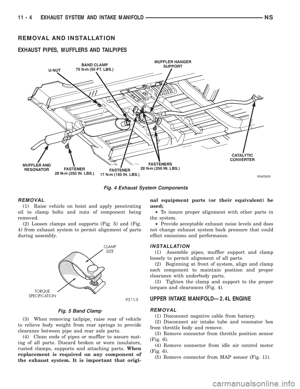
(2) Loosen clamps and supports (Fig. 5) and (Fig.
4) from exhaust system to permit alignment of parts
during assembly.
(3) When removing tailpipe, raise rear of vehicle
to relieve body weight from rear springs to provide
clearance between pipe and rear axle parts.
(4) Clean ends of pipes or muffler to assure mat-
ing of all parts. Discard broken or worn insulators,
rusted clamps, supports and attaching parts.When
replacement is required on any component of
the exhaust system. It is important that origi-nal equipment parts (or their equivalent) be
used;
²To insure proper alignment with other parts in
the system.
²Provide acceptable exhaust noise levels and does
not change exhaust system back pressure that could
effect emissions and performance.
INSTALLATION
(1) Assemble pipes, muffler support and clamp
loosely to permit alignment of all parts.
(2) Beginning at front of system, align and clamp
each component to maintain position and proper
clearance with underbody parts.
(3) Tighten the clamp and support to the proper
torques and clearances (Fig. 4).
UPPER INTAKE MANIFOLDÐ2.4L ENGINE
REMOVAL
(1) Disconnect negative cable from battery.
(2) Disconnect air intake tube and resonator box
from throttle body and remove.
(3) Remove connector from throttle position sensor
(Fig. 6).
(4) Remove connector from idle air control motor
(Fig. 6).
(5) Remove connector from MAP sensor (Fig. 11).
Fig. 4 Exhaust System Components
Fig. 5 Band Clamp
11 - 4 EXHAUST SYSTEM AND INTAKE MANIFOLDNS
Page 1267 of 1938
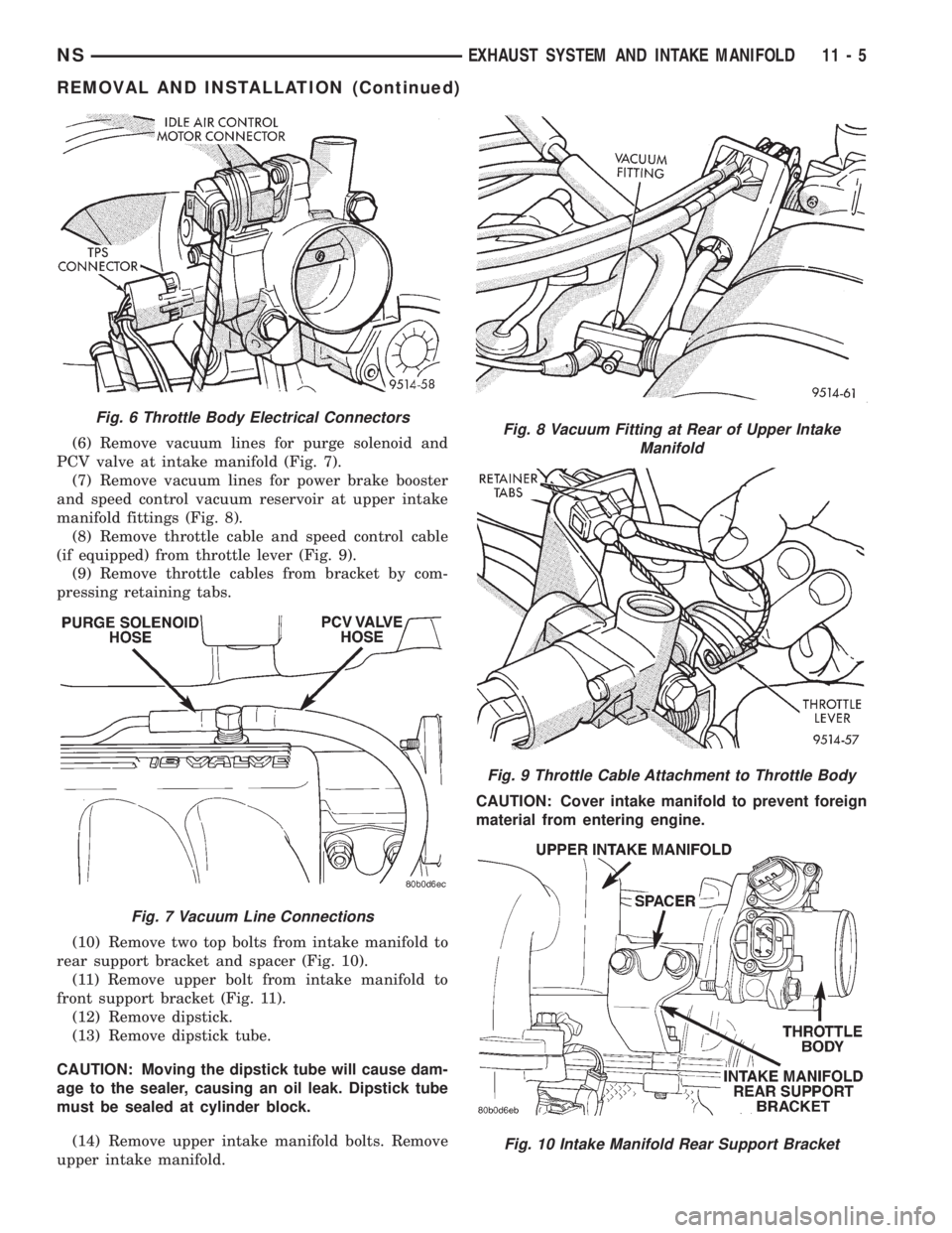
(6) Remove vacuum lines for purge solenoid and
PCV valve at intake manifold (Fig. 7).
(7) Remove vacuum lines for power brake booster
and speed control vacuum reservoir at upper intake
manifold fittings (Fig. 8).
(8) Remove throttle cable and speed control cable
(if equipped) from throttle lever (Fig. 9).
(9) Remove throttle cables from bracket by com-
pressing retaining tabs.
(10) Remove two top bolts from intake manifold to
rear support bracket and spacer (Fig. 10).
(11) Remove upper bolt from intake manifold to
front support bracket (Fig. 11).
(12) Remove dipstick.
(13) Remove dipstick tube.
CAUTION: Moving the dipstick tube will cause dam-
age to the sealer, causing an oil leak. Dipstick tube
must be sealed at cylinder block.
(14) Remove upper intake manifold bolts. Remove
upper intake manifold.CAUTION: Cover intake manifold to prevent foreign
material from entering engine.
Fig. 6 Throttle Body Electrical Connectors
Fig. 7 Vacuum Line Connections
Fig. 8 Vacuum Fitting at Rear of Upper Intake
Manifold
Fig. 9 Throttle Cable Attachment to Throttle Body
Fig. 10 Intake Manifold Rear Support Bracket
NSEXHAUST SYSTEM AND INTAKE MANIFOLD 11 - 5
REMOVAL AND INSTALLATION (Continued)