1996 CHRYSLER VOYAGER engine
[x] Cancel search: enginePage 1277 of 1938
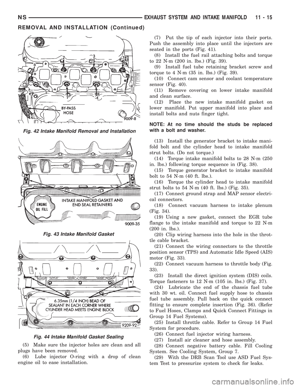
(5) Make sure the injector holes are clean and all
plugs have been removed.
(6) Lube injector O-ring with a drop of clean
engine oil to ease installation.(7) Put the tip of each injector into their ports.
Push the assembly into place until the injectors are
seated in the ports (Fig. 41).
(8) Install the fuel rail attaching bolts and torque
to 22 N´m (200 in. lbs.) (Fig. 39).
(9) Install fuel tube retaining bracket screw and
torque to 4 N´m (35 in. lbs.) (Fig. 39).
(10) Connect cam sensor and coolant temperature
sensor (Fig. 40).
(11) Remove covering on lower intake manifold
and clean surface.
(12) Place the new intake manifold gasket on
lower manifold. Put upper manifold into place and
install bolts and nuts finger tight.
NOTE: At no time should the studs be replaced
with a bolt and washer.
(13) Install the generator bracket to intake mani-
fold bolt and the cylinder head to intake manifold
strut bolts. (Do not torque.)
(14) Torque intake manifold bolts to 28 N´m (250
in. lbs.) following torque sequence in (Fig. 38).
(15) Torque generator bracket to intake manifold
bolt to 54 N´m (40 ft. lbs.).
(16) Torque the cylinder head to intake manifold
strut bolts to 54 N´m (40 ft. lbs.) (Fig. 35).
(17) Connect ground strap and MAP sensor electri-
cal connectors.
(18) Connect vacuum harness to intake plenum
(Fig. 34).
(19) Using a new gasket, connect the EGR tube
flange to the intake manifold and torque to 22 N´m
(200 in. lbs.).
(20) Clip wiring harness into the hole in the throt-
tle cable bracket.
(21) Connect the wiring connectors to the throttle
position sensor (TPS) and Automatic Idle Speed (AIS)
motor (Fig. 33).
(22) Connect vacuum harness to throttle body (Fig.
33).
(23) Install the direct ignition system (DIS) coils.
Torque fasteners to 12 N´m (105 in. lbs.) (Fig. 37).
(24) Lubricate the end of the chassis fuel tube
with 30 wt. oil. Connect fuel supply hose to chassis
fuel tube assembly. Pull back on the quick connect
fitting to ensure complete insertion (Fig. 36). (Refer
to Fuel Hoses, Clamps and Quick Connect Fittings in
Group 14 Fuel Systems).
(25) Install throttle cable. Refer to Group 14 Fuel
System for procedure.
(26) Connect fuel injector wiring harness.
(27) Install air cleaner and hose assembly.
(28) Connect negative battery cable. Fill Cooling
System. See Cooling System, Group 7.
(29) With the DRB Scan Tool use ASD Fuel Sys-
tem Test to pressurize system to check for leaks.
Fig. 42 Intake Manifold Removal and Installation
Fig. 43 Intake Manifold Gasket
Fig. 44 Intake Manifold Gasket Sealing
NSEXHAUST SYSTEM AND INTAKE MANIFOLD 11 - 15
REMOVAL AND INSTALLATION (Continued)
Page 1278 of 1938

CAUTION: When using the ASD Fuel System Test,
The Auto Shutdown (ASD) Relay will remain ener-
gized for 7 minutes or until the ignition switch is
turned to the OFF position, or Stop All Test is
selected.
EXHAUST MANIFOLDSÐ3.3/3.8L ENGINE
REMOVAL
(1) Disconnect battery negative cable.
(2) Remove accessory drive belt. Refer to Accessory
Drive section located in Group 7 Cooling System for
procedure.
(3) Remove generator.
(4) Raise vehicle and disconnect exhaust pipe
from rear (cowl side) exhaust manifold at flex-joint.
(5) Disconnect down stream oxygen sensor connec-
tor.
(6) Lower exhaust system to gain access to rear
manifold.
(7) Separate EGR tube from rear manifold and
disconnect Heated Oxygen Sensor lead wire (Fig. 45).
(8) Remove heat shield from rear engine mount.
(9) Remove Generator/Power Steering Support
Strut (Fig. 45).
(10) Remove bolts attaching crossover pipe to
manifold (Fig. 45).
(11) Disconnect up stream oxygen sensor connec-
tor.
(12) Remove bolts attaching rear manifold to cyl-
inder head and remove manifold.
(13) Lower vehicle and remove screws attaching
front heat shield to front manifold (Fig. 46).
(14) Remove bolts fastening crossover pipe to
front exhaust manifold and nuts fastening manifold
to cylinder head. Remove assemblies (Fig. 47).
(15) Inspect and clean manifold. Refer to Cleaning
and Inspection outlined in this section for proce-
dures.
INSTALLATION
(1) Install rear exhaust manifold and tighten
attaching bolts to 23 N´m (200 in. lbs.).
(2) Install generator.
NOTE: Inspect crossover pipe fasteners for dam-
age from heat and corrosion. Replace if necessary.
(3) Using new gasket attach crossover pipe to
exhaust manifold and tighten bolts to 54 N´m (40 ft.
lbs.) and connect oxygen sensor lead (Fig. 45).
(4) Install EGR Tube and Generator/Power Steer-
ing Strut (Fig. 45).
(5) Using new gaskets install front exhaust mani-
fold and tighten attaching bolts to 23 N´m (200 in.
lbs.).(6) Attach exhaust crossover with a new gasket
and tighten fasteners to 54 N´m (40 ft. lbs.) (Fig. 47).
(7) Connect up stream oxygen sensor connector.
(8) Install exhaust system.
Fig. 45 EGR Tube, Heated Oxygen Sensor and
Generator/Power Steering Strut
Fig. 46 Heat ShieldÐFront
Fig. 47 Crossover Pipe
11 - 16 EXHAUST SYSTEM AND INTAKE MANIFOLDNS
REMOVAL AND INSTALLATION (Continued)
Page 1283 of 1938
FRAME
INDEX
page page
REMOVAL AND INSTALLATION
FRONT CROSSMEMBER MOUNT BUSHINGS . . . 5
FRONT CROSSMEMBER................... 3SPECIFICATIONS
FRAME AND BODY OPENING DIMENSIONS.... 5
REMOVAL AND INSTALLATION
FRONT CROSSMEMBER
The front suspension crossmember must be
installed in the design location to achieve proper
front end suspension alignment. If the crossmember
is removed without applying reference marks on the
frame rails, align the crossmember according to the
dimensions provided in this group.
NOTE: If the caged nuts in the frame rails become
damaged and cannot be reused, a replacement nut
can be obtained through a MoparTParts supplier.
REMOVAL
(1) Disconnect battery negative cable.
(2) Remove steering column lower cover from
instrument panel. Refer to Group 8E, Instrument
Panel and Systems.
(3) Remove knee blocker reinforcement. Refer to
Group 8E, Instrument Panel and Systems.
(4) Position steering so front wheels are straight
ahead.
CAUTION: Do not rotate steering wheel after disen-
gaging lower coupling from steering gear, damage
to airbag clock spring can result.
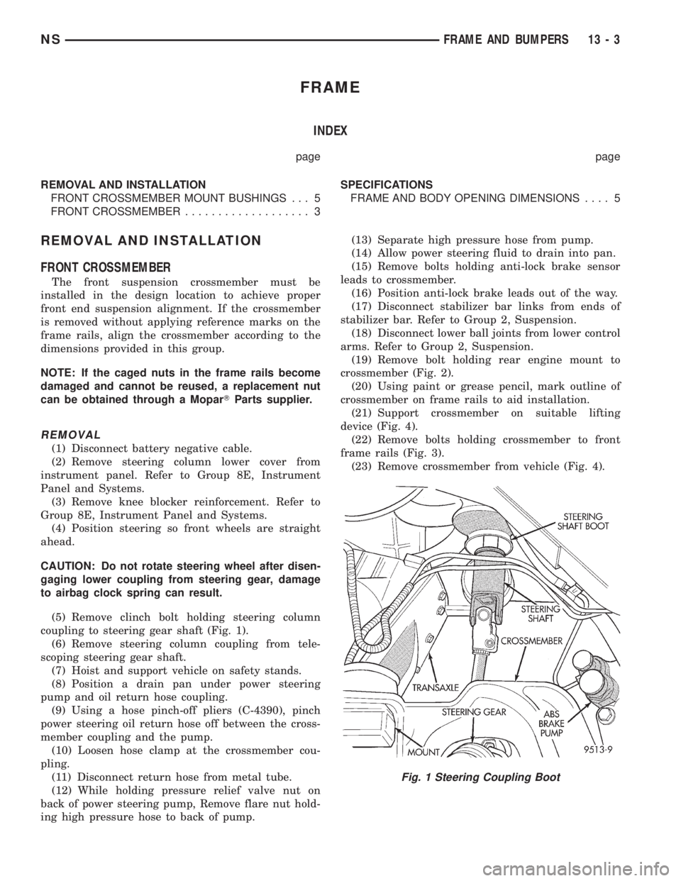
(5) Remove clinch bolt holding steering column
coupling to steering gear shaft (Fig. 1).
(6) Remove steering column coupling from tele-
scoping steering gear shaft.
(7) Hoist and support vehicle on safety stands.
(8) Position a drain pan under power steering
pump and oil return hose coupling.
(9) Using a hose pinch-off pliers (C-4390), pinch
power steering oil return hose off between the cross-
member coupling and the pump.
(10) Loosen hose clamp at the crossmember cou-
pling.
(11) Disconnect return hose from metal tube.
(12) While holding pressure relief valve nut on
back of power steering pump, Remove flare nut hold-
ing high pressure hose to back of pump.(13) Separate high pressure hose from pump.
(14) Allow power steering fluid to drain into pan.
(15) Remove bolts holding anti-lock brake sensor
leads to crossmember.
(16) Position anti-lock brake leads out of the way.
(17) Disconnect stabilizer bar links from ends of
stabilizer bar. Refer to Group 2, Suspension.
(18) Disconnect lower ball joints from lower control
arms. Refer to Group 2, Suspension.
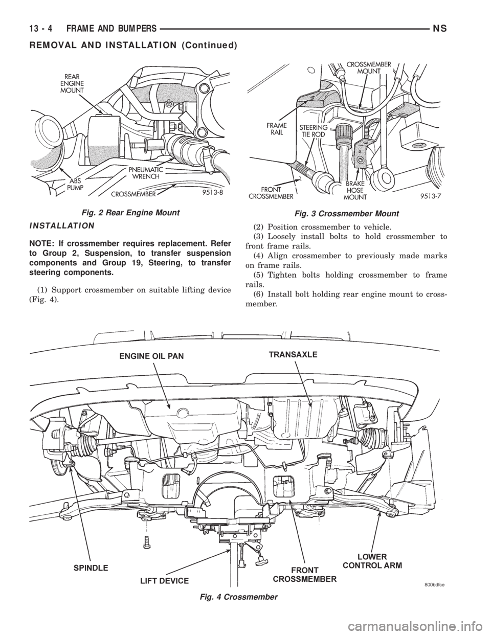
(19) Remove bolt holding rear engine mount to
crossmember (Fig. 2).
(20) Using paint or grease pencil, mark outline of
crossmember on frame rails to aid installation.
(21) Support crossmember on suitable lifting
device (Fig. 4).
(22) Remove bolts holding crossmember to front
frame rails (Fig. 3).
(23) Remove crossmember from vehicle (Fig. 4).
Fig. 1 Steering Coupling Boot
NSFRAME AND BUMPERS 13 - 3
Page 1284 of 1938
INSTALLATION
NOTE: If crossmember requires replacement. Refer
to Group 2, Suspension, to transfer suspension
components and Group 19, Steering, to transfer
steering components.
(1) Support crossmember on suitable lifting device
(Fig. 4).(2) Position crossmember to vehicle.
(3) Loosely install bolts to hold crossmember to
front frame rails.
(4) Align crossmember to previously made marks
on frame rails.
(5) Tighten bolts holding crossmember to frame
rails.
(6) Install bolt holding rear engine mount to cross-
member.
Fig. 4 Crossmember
Fig. 2 Rear Engine MountFig. 3 Crossmember Mount
13 - 4 FRAME AND BUMPERSNS
REMOVAL AND INSTALLATION (Continued)
Page 1287 of 1938
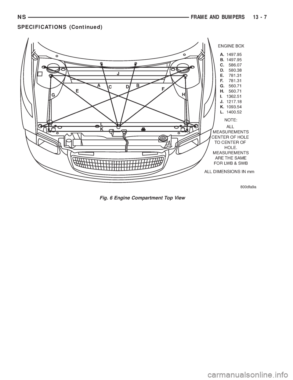
Fig. 6 Engine Compartment Top View
NSFRAME AND BUMPERS 13 - 7
SPECIFICATIONS (Continued)
Page 1288 of 1938
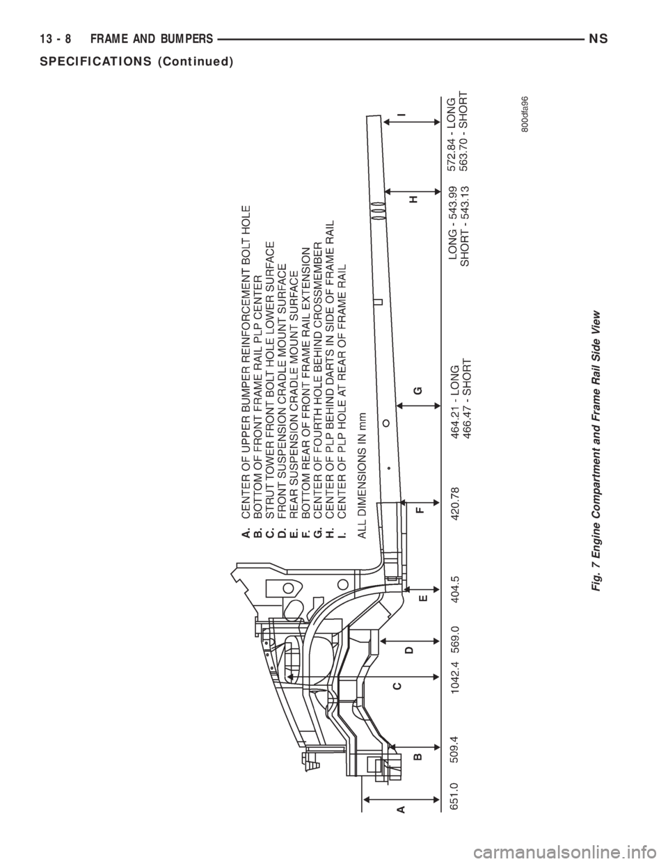
Fig. 7 Engine Compartment and Frame Rail Side View
13 - 8 FRAME AND BUMPERSNS
SPECIFICATIONS (Continued)
Page 1293 of 1938
FRAME AND BUMPERS
CONTENTS
page
FRAME................................ 1
FRAME
INDEX
page page
REMOVAL AND INSTALLATION
FRONT TOW HOOK BRACKET............. 1REAR TOW HOOK BRACKET.............. 1
REMOVAL AND INSTALLATION
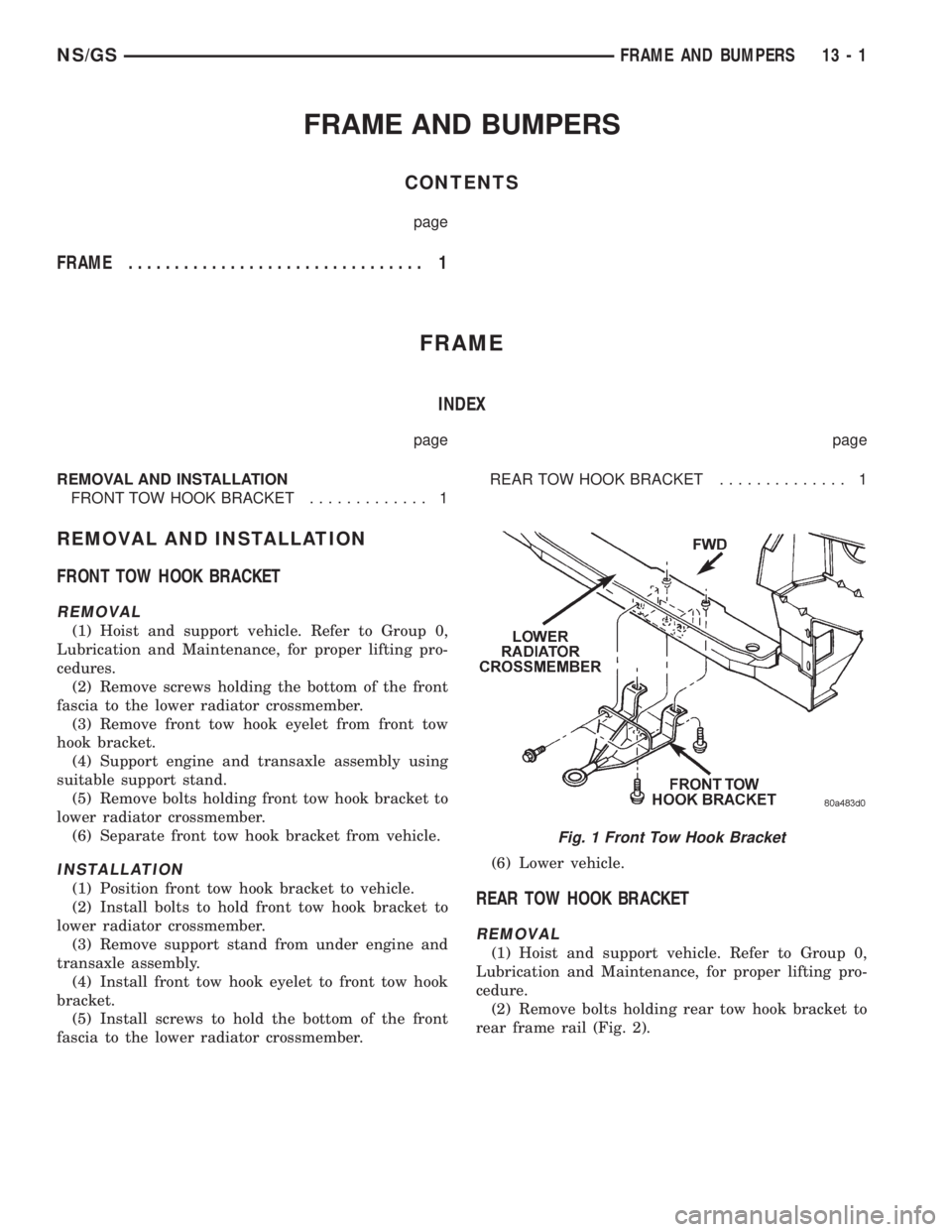
FRONT TOW HOOK BRACKET
REMOVAL
(1) Hoist and support vehicle. Refer to Group 0,
Lubrication and Maintenance, for proper lifting pro-
cedures.
(2) Remove screws holding the bottom of the front
fascia to the lower radiator crossmember.
(3) Remove front tow hook eyelet from front tow
hook bracket.
(4) Support engine and transaxle assembly using
suitable support stand.
(5) Remove bolts holding front tow hook bracket to
lower radiator crossmember.
(6) Separate front tow hook bracket from vehicle.
INSTALLATION
(1) Position front tow hook bracket to vehicle.
(2) Install bolts to hold front tow hook bracket to
lower radiator crossmember.
(3) Remove support stand from under engine and
transaxle assembly.
(4) Install front tow hook eyelet to front tow hook
bracket.
(5) Install screws to hold the bottom of the front
fascia to the lower radiator crossmember.(6) Lower vehicle.REAR TOW HOOK BRACKET
REMOVAL
(1) Hoist and support vehicle. Refer to Group 0,
Lubrication and Maintenance, for proper lifting pro-
cedure.
(2) Remove bolts holding rear tow hook bracket to
rear frame rail (Fig. 2).
Fig. 1 Front Tow Hook Bracket
NS/GSFRAME AND BUMPERS 13 - 1
Page 1295 of 1938
FUEL SYSTEM
CONTENTS
page page
FUEL DELIVERY SYSTEM................... 4
FUEL INJECTION SYSTEM................. 29GENERAL INFORMATION................... 1
GENERAL INFORMATION
INDEX
page page
GENERAL INFORMATION
CRUISING RANGE........................ 3
E-85 GENERAL INFORMATION.............. 2
ETHANOL FUEL (E-85).................... 2
FUEL REQUIREMENTS.................... 1
FUEL REQUIREMENTS.................... 2GASOLINE/OXYGENATE BLENDS............ 2
INTRODUCTION......................... 1
PCM REPLACEMENT..................... 1
REPLACEMENT PARTS.................... 3
STARTING.............................. 2
GENERAL INFORMATION
INTRODUCTION
Throughout this group, references may be made to
a particular vehicle by letter or number designation.
A chart showing the breakdown of these designations
is included in the Introduction Section at the front of
this service manual.
The Evaporation Control System, is also considered
part of the fuel system. The system reduces the emis-
sion of fuel vapor into the atmosphere.
The description and function of the Evaporation
Control System is found in Group 25 of this manual.
PCM REPLACEMENT
USE THE DRB SCAN TOOL TO REPROGRAM
THE NEW PCM WITH THE VEHICLES ORIGI-
NAL IDENTIFICATION NUMBER (VIN) AND
THE VEHICLES ORIGINAL MILEAGE. IF THIS
STEP IS NOT DONE A DIAGNOSTIC TROUBLE
CODE (DTC) MAY BE SET.
FUEL REQUIREMENTS
Your vehicle was designed to meet all emission reg-
ulations and provide excellent fuel economy when
using high quality unleaded gasoline.
Use unleaded gasolines having a minimum posted
octane of 87.
If your vehicle develops occasional light spark
knock (ping) at low engine speeds this is not harm-
ful. However; continued heavy knock at high speeds
can cause damage and should be reported to your
dealer immediately. Engine damage as a result of
heavy knock operation may not be covered by the
new vehicle warranty.
In addition to using unleaded gasoline with the
proper octane rating, those that contain detergents,
corrosion and stability additives are recommended.
Using gasolines that have these additives will help
improve fuel economy, reduce emissions, and main-
tain vehicle performance.
Poor quality gasoline can cause problems such as
hard starting, stalling, and stumble. If you experi-
ence these problems, try another brand of gasoline
before considering service for the vehicle.
NSFUEL SYSTEM 14 - 1