1996 CHRYSLER VOYAGER engine
[x] Cancel search: enginePage 1268 of 1938
INSTALLATION
(1) Install new upper intake manifold gasket.
NOTE: Center outboard fastener is a double stud.
(2) Tighten upper intake manifold fasteners start-
ing at center and progressing outward in both direc-
tions. Tighten bolts to 28 N´m (250 in. lbs.). Repeat
this procedures until all fasteners are at specified
torque.
(3) Install dipstick tube. Seal tube to cylinder
block using MopartStud N' Bearing Mount Adhe-
sive. Tighten dipstick tube fastener to 12 N´m (105
in. lbs.)
(4) Install dipstick.
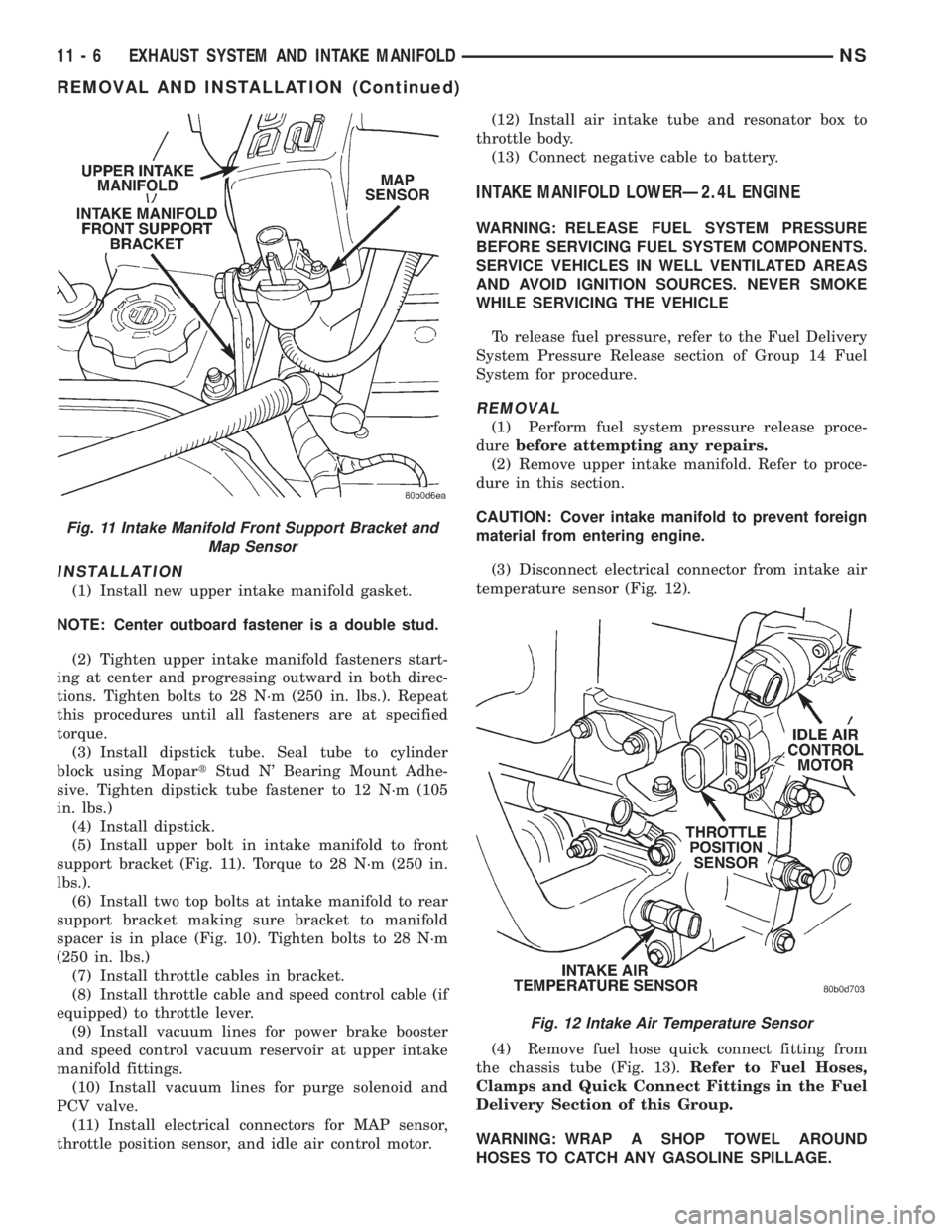
(5) Install upper bolt in intake manifold to front
support bracket (Fig. 11). Torque to 28 N´m (250 in.
lbs.).
(6) Install two top bolts at intake manifold to rear
support bracket making sure bracket to manifold
spacer is in place (Fig. 10). Tighten bolts to 28 N´m
(250 in. lbs.)
(7) Install throttle cables in bracket.
(8) Install throttle cable and speed control cable (if
equipped) to throttle lever.
(9) Install vacuum lines for power brake booster
and speed control vacuum reservoir at upper intake
manifold fittings.
(10) Install vacuum lines for purge solenoid and
PCV valve.
(11) Install electrical connectors for MAP sensor,
throttle position sensor, and idle air control motor.(12) Install air intake tube and resonator box to
throttle body.
(13) Connect negative cable to battery.
INTAKE MANIFOLD LOWERÐ2.4L ENGINE
WARNING: RELEASE FUEL SYSTEM PRESSURE
BEFORE SERVICING FUEL SYSTEM COMPONENTS.
SERVICE VEHICLES IN WELL VENTILATED AREAS
AND AVOID IGNITION SOURCES. NEVER SMOKE
WHILE SERVICING THE VEHICLE
To release fuel pressure, refer to the Fuel Delivery
System Pressure Release section of Group 14 Fuel
System for procedure.
REMOVAL
(1) Perform fuel system pressure release proce-
durebefore attempting any repairs.
(2) Remove upper intake manifold. Refer to proce-
dure in this section.
CAUTION: Cover intake manifold to prevent foreign
material from entering engine.
(3) Disconnect electrical connector from intake air
temperature sensor (Fig. 12).
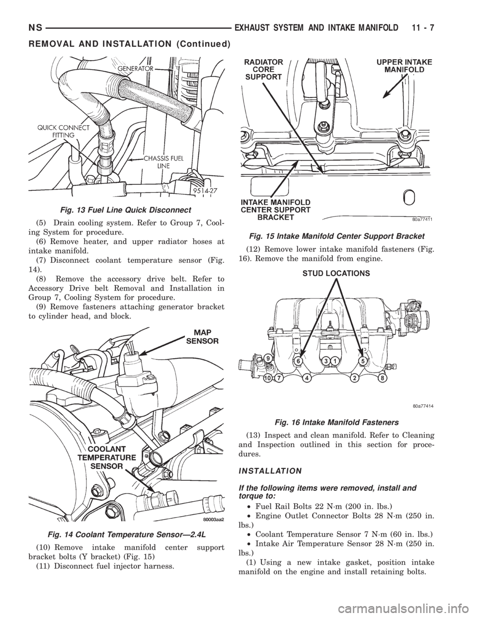
(4) Remove fuel hose quick connect fitting from
the chassis tube (Fig. 13).Refer to Fuel Hoses,
Clamps and Quick Connect Fittings in the Fuel
Delivery Section of this Group.
WARNING: WRAP A SHOP TOWEL AROUND
HOSES TO CATCH ANY GASOLINE SPILLAGE.
Fig. 11 Intake Manifold Front Support Bracket and
Map Sensor
Fig. 12 Intake Air Temperature Sensor
11 - 6 EXHAUST SYSTEM AND INTAKE MANIFOLDNS
REMOVAL AND INSTALLATION (Continued)
Page 1269 of 1938
(5) Drain cooling system. Refer to Group 7, Cool-
ing System for procedure.
(6) Remove heater, and upper radiator hoses at
intake manifold.
(7) Disconnect coolant temperature sensor (Fig.
14).
(8) Remove the accessory drive belt. Refer to
Accessory Drive belt Removal and Installation in
Group 7, Cooling System for procedure.
(9) Remove fasteners attaching generator bracket
to cylinder head, and block.
(10) Remove intake manifold center support
bracket bolts (Y bracket) (Fig. 15)
(11) Disconnect fuel injector harness.(12) Remove lower intake manifold fasteners (Fig.
16). Remove the manifold from engine.
(13) Inspect and clean manifold. Refer to Cleaning
and Inspection outlined in this section for proce-
dures.
INSTALLATION
If the following items were removed, install and
torque to:
²Fuel Rail Bolts 22 N´m (200 in. lbs.)
²Engine Outlet Connector Bolts 28 N´m (250 in.
lbs.)
²Coolant Temperature Sensor 7 N´m (60 in. lbs.)
²Intake Air Temperature Sensor 28 N´m (250 in.
lbs.)
(1) Using a new intake gasket, position intake
manifold on the engine and install retaining bolts.
Fig. 13 Fuel Line Quick Disconnect
Fig. 14 Coolant Temperature SensorÐ2.4L
Fig. 15 Intake Manifold Center Support Bracket
Fig. 16 Intake Manifold Fasteners
NSEXHAUST SYSTEM AND INTAKE MANIFOLD 11 - 7
REMOVAL AND INSTALLATION (Continued)
Page 1270 of 1938
(2) Tighten intake manifold fasteners in the fol-
lowing sequence (Fig. 16). Torque to 23 N´m (200 in.
lbs.). Repeat this procedure until all bolts are at
specified torque.
(3) Install intake manifold center support bracket
bolts (Y bracket):
²Fastener to block 54 N´m (40 ft. lbs.)
²Fastener to intake 28 N´m (250 in. lbs.)
(4) Install fuel hose quick connector fitting to
chassis tubes.Refer to Fuel Hoses, Clamps and
Quick Connect Fittings in Group 14, Fuel Deliv-
ery.Push the fitting onto the chassis tube until it
clicks into place. Pull on the fitting to ensure com-
plete insertion.
(5) Reverse removal procedures 2 through 12 for
installation.
CAUTION: When using the ASD Fuel System Test,
the ASD relay and fuel pump relay remain energized
for 7 minutes or until the test is stopped, or until
the ignition switch is turned to the Off position.
(6) With the ignition key in ON position, access
the DRB scan tool ASD Fuel System Test to pressur-
ize the fuel system. Check for leaks.
EXHAUST MANIFOLDÐ2.4L ENGINE
REMOVAL
(1) Raise vehicle and disconnect exhaust pipe from
the exhaust manifold at the flex-joint.
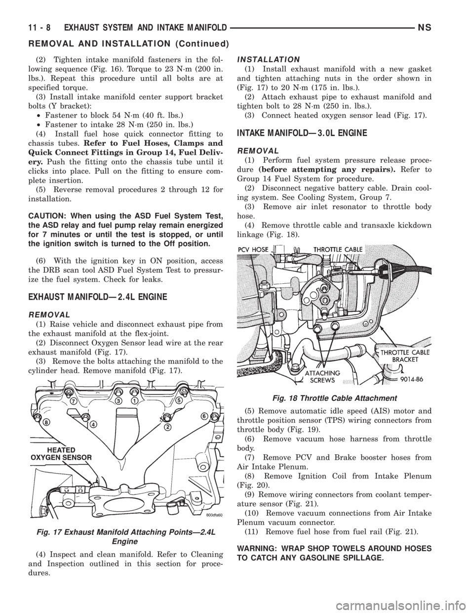
(2) Disconnect Oxygen Sensor lead wire at the rear
exhaust manifold (Fig. 17).
(3) Remove the bolts attaching the manifold to the
cylinder head. Remove manifold (Fig. 17).
(4) Inspect and clean manifold. Refer to Cleaning
and Inspection outlined in this section for proce-
dures.
INSTALLATION
(1) Install exhaust manifold with a new gasket
and tighten attaching nuts in the order shown in
(Fig. 17) to 20 N´m (175 in. lbs.).
(2) Attach exhaust pipe to exhaust manifold and
tighten bolt to 28 N´m (250 in. lbs.).
(3) Connect heated oxygen sensor lead (Fig. 17).
INTAKE MANIFOLDÐ3.0L ENGINE
REMOVAL
(1) Perform fuel system pressure release proce-
dure(before attempting any repairs).Refer to
Group 14 Fuel System for procedure.
(2) Disconnect negative battery cable. Drain cool-
ing system. See Cooling System, Group 7.
(3) Remove air inlet resonator to throttle body
hose.
(4) Remove throttle cable and transaxle kickdown
linkage (Fig. 18).
(5) Remove automatic idle speed (AIS) motor and
throttle position sensor (TPS) wiring connectors from
throttle body (Fig. 19).
(6) Remove vacuum hose harness from throttle
body.
(7) Remove PCV and Brake booster hoses from
Air Intake Plenum.
(8) Remove Ignition Coil from Intake Plenum
(Fig. 20).
(9) Remove wiring connectors from coolant temper-
ature sensor (Fig. 21).
(10) Remove vacuum connections from Air Intake
Plenum vacuum connector.
(11) Remove fuel hose from fuel rail (Fig. 21).
WARNING: WRAP SHOP TOWELS AROUND HOSES
TO CATCH ANY GASOLINE SPILLAGE.
Fig. 17 Exhaust Manifold Attaching PointsÐ2.4L
Engine
Fig. 18 Throttle Cable Attachment
11 - 8 EXHAUST SYSTEM AND INTAKE MANIFOLDNS
REMOVAL AND INSTALLATION (Continued)
Page 1271 of 1938
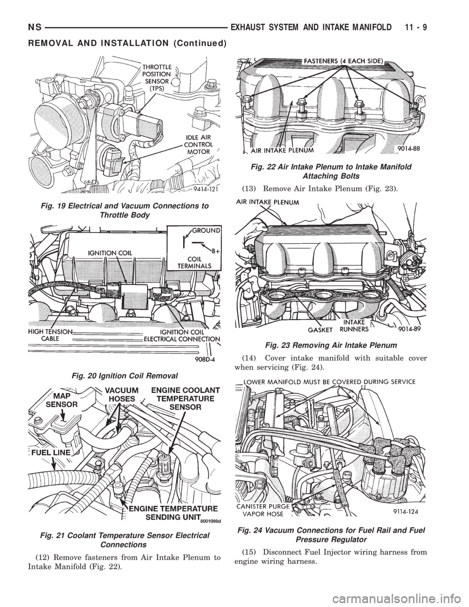
(12) Remove fasteners from Air Intake Plenum to
Intake Manifold (Fig. 22).(13) Remove Air Intake Plenum (Fig. 23).
(14) Cover intake manifold with suitable cover
when servicing (Fig. 24).
(15) Disconnect Fuel Injector wiring harness from
engine wiring harness.
Fig. 19 Electrical and Vacuum Connections to
Throttle Body
Fig. 20 Ignition Coil Removal
Fig. 21 Coolant Temperature Sensor Electrical
Connections
Fig. 22 Air Intake Plenum to Intake Manifold
Attaching Bolts
Fig. 23 Removing Air Intake Plenum
Fig. 24 Vacuum Connections for Fuel Rail and Fuel
Pressure Regulator
NSEXHAUST SYSTEM AND INTAKE MANIFOLD 11 - 9
REMOVAL AND INSTALLATION (Continued)
Page 1272 of 1938
(16) Remove fuel rail attaching bolts and lift fuel
rail assembly from intake manifold.
(17) Separate radiator hose from thermostat hous-
ing and heater hose from heater pipe.
(18) Remove nut and washer assemblies and
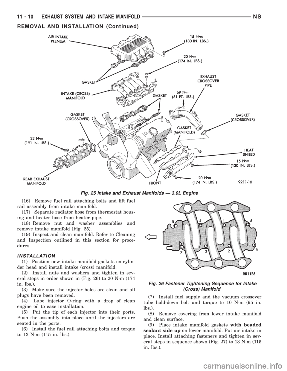
remove intake manifold (Fig. 25).
(19) Inspect and clean manifold. Refer to Cleaning
and Inspection outlined in this section for proce-
dures.
INSTALLATION
(1) Position new intake manifold gaskets on cylin-
der head and install intake (cross) manifold.
(2) Install nuts and washers and tighten in sev-
eral steps in order shown in (Fig. 26) to 20 N´m (174
in. lbs.).
(3) Make sure the injector holes are clean and all
plugs have been removed.
(4) Lube injector O-ring with a drop of clean
engine oil to ease installation.
(5) Put the tip of each injector into their ports.
Push the assembly into place until the injectors are
seated in the ports.
(6) Install the fuel rail attaching bolts and torque
to 13 N´m (115 in. lbs.).(7) Install fuel supply and the vacuum crossover
tube hold-down bolt and torque to 10 N´m (95 in.
lbs.).
(8) Remove covering from lower intake manifold
and clean surface.
(9) Place intake manifold gasketswith beaded
sealant side upon lower manifold. Put air intake in
place. Install attaching fasteners and tighten in sev-
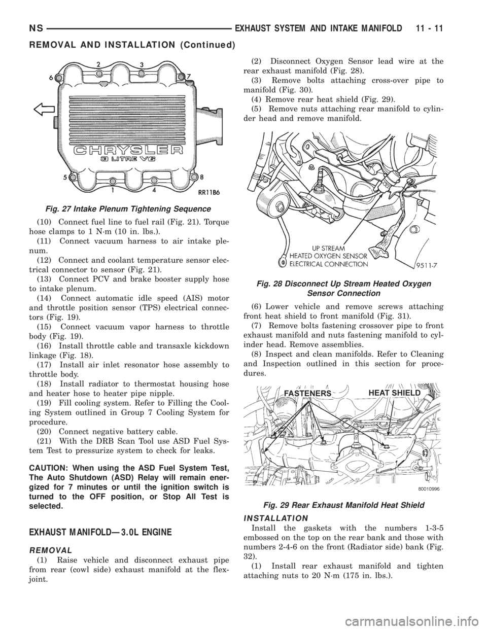
eral steps in sequence shown (Fig. 27) to 13 N´m (115
in. lbs.).
Fig. 25 Intake and Exhaust Manifolds Ð 3.0L Engine
Fig. 26 Fastener Tightening Sequence for Intake
(Cross) Manifold
11 - 10 EXHAUST SYSTEM AND INTAKE MANIFOLDNS
REMOVAL AND INSTALLATION (Continued)
Page 1273 of 1938
(10) Connect fuel line to fuel rail (Fig. 21). Torque
hose clamps to 1 N´m (10 in. lbs.).
(11) Connect vacuum harness to air intake ple-
num.
(12) Connect and coolant temperature sensor elec-
trical connector to sensor (Fig. 21).
(13) Connect PCV and brake booster supply hose
to intake plenum.
(14) Connect automatic idle speed (AIS) motor
and throttle position sensor (TPS) electrical connec-
tors (Fig. 19).
(15) Connect vacuum vapor harness to throttle
body (Fig. 19).
(16) Install throttle cable and transaxle kickdown
linkage (Fig. 18).
(17) Install air inlet resonator hose assembly to
throttle body.
(18) Install radiator to thermostat housing hose
and heater hose to heater pipe nipple.
(19) Fill cooling system. Refer to Filling the Cool-
ing System outlined in Group 7 Cooling System for
procedure.
(20) Connect negative battery cable.
(21) With the DRB Scan Tool use ASD Fuel Sys-
tem Test to pressurize system to check for leaks.
CAUTION: When using the ASD Fuel System Test,
The Auto Shutdown (ASD) Relay will remain ener-
gized for 7 minutes or until the ignition switch is
turned to the OFF position, or Stop All Test is
selected.
EXHAUST MANIFOLDÐ3.0L ENGINE
REMOVAL
(1) Raise vehicle and disconnect exhaust pipe
from rear (cowl side) exhaust manifold at the flex-
joint.(2) Disconnect Oxygen Sensor lead wire at the
rear exhaust manifold (Fig. 28).
(3) Remove bolts attaching cross-over pipe to
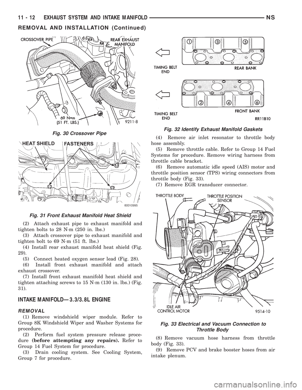
manifold (Fig. 30).
(4) Remove rear heat shield (Fig. 29).
(5) Remove nuts attaching rear manifold to cylin-
der head and remove manifold.
(6) Lower vehicle and remove screws attaching
front heat shield to front manifold (Fig. 31).
(7) Remove bolts fastening crossover pipe to front
exhaust manifold and nuts fastening manifold to cyl-
inder head. Remove assemblies.
(8) Inspect and clean manifolds. Refer to Cleaning
and Inspection outlined in this section for proce-
dures.
INSTALLATION
Install the gaskets with the numbers 1-3-5
embossed on the top on the rear bank and those with
numbers 2-4-6 on the front (Radiator side) bank (Fig.
32).
(1) Install rear exhaust manifold and tighten
attaching nuts to 20 N´m (175 in. lbs.).
Fig. 27 Intake Plenum Tightening Sequence
Fig. 28 Disconnect Up Stream Heated Oxygen
Sensor Connection
Fig. 29 Rear Exhaust Manifold Heat Shield
NSEXHAUST SYSTEM AND INTAKE MANIFOLD 11 - 11
REMOVAL AND INSTALLATION (Continued)
Page 1274 of 1938
(2) Attach exhaust pipe to exhaust manifold and
tighten bolts to 28 N´m (250 in. lbs.)
(3) Attach crossover pipe to exhaust manifold and
tighten bolt to 69 N´m (51 ft. lbs.)
(4) Install rear exhaust manifold heat shield (Fig.
29).
(5) Connect heated oxygen sensor lead (Fig. 28).
(6) Install front exhaust manifold and attach
exhaust crossover.
(7) Install front exhaust manifold heat shield and
tighten attaching screws to 15 N´m (130 in. lbs.) (Fig.
31).
INTAKE MANIFOLDÐ3.3/3.8L ENGINE
REMOVAL
(1) Remove windshield wiper module. Refer to
Group 8K Windshield Wiper and Washer Systems for
procedure.
(2) Perform fuel system pressure release proce-
dure(before attempting any repairs).Refer to
Group 14 Fuel System for procedure.
(3) Drain cooling system. See Cooling System,
Group 7 for procedure.(4) Remove air inlet resonator to throttle body
hose assembly.
(5) Remove throttle cable. Refer to Group 14 Fuel
Systems for procedure. Remove wiring harness from
throttle cable bracket.
(6) Remove automatic idle speed (AIS) motor and
throttle position sensor (TPS) wiring connectors from
throttle body (Fig. 33).
(7) Remove EGR transducer connector.
(8) Remove vacuum hose harness from throttle
body (Fig. 33).
(9) Remove PCV and brake booster hoses from air
intake plenum.
Fig. 30 Crossover Pipe
Fig. 31 Front Exhaust Manifold Heat Shield
Fig. 32 Identify Exhaust Manifold Gaskets
Fig. 33 Electrical and Vacuum Connection to
Throttle Body
11 - 12 EXHAUST SYSTEM AND INTAKE MANIFOLDNS
REMOVAL AND INSTALLATION (Continued)
Page 1275 of 1938
(10) Disconnect MAP Sensor electrical connection
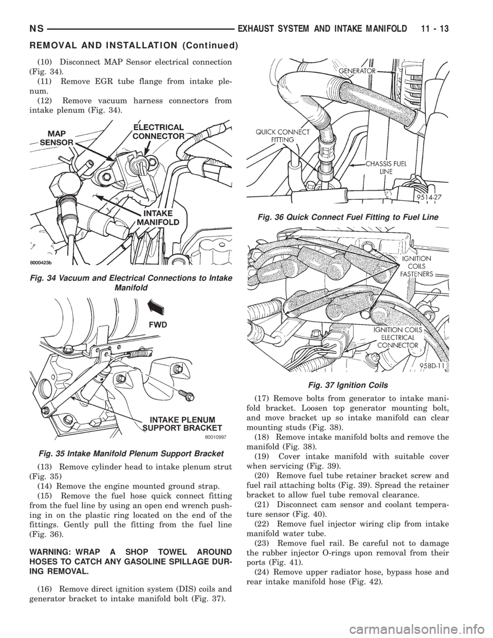
(Fig. 34).
(11) Remove EGR tube flange from intake ple-
num.
(12) Remove vacuum harness connectors from
intake plenum (Fig. 34).
(13) Remove cylinder head to intake plenum strut
(Fig. 35)
(14) Remove the engine mounted ground strap.
(15) Remove the fuel hose quick connect fitting
from the fuel line by using an open end wrench push-
ing in on the plastic ring located on the end of the
fittings. Gently pull the fitting from the fuel line
(Fig. 36).
WARNING: WRAP A SHOP TOWEL AROUND
HOSES TO CATCH ANY GASOLINE SPILLAGE DUR-
ING REMOVAL.
(16) Remove direct ignition system (DIS) coils and
generator bracket to intake manifold bolt (Fig. 37).(17) Remove bolts from generator to intake mani-
fold bracket. Loosen top generator mounting bolt,
and move bracket up so intake manifold can clear
mounting studs (Fig. 38).
(18) Remove intake manifold bolts and remove the
manifold (Fig. 38).
(19) Cover intake manifold with suitable cover
when servicing (Fig. 39).
(20) Remove fuel tube retainer bracket screw and
fuel rail attaching bolts (Fig. 39). Spread the retainer
bracket to allow fuel tube removal clearance.
(21) Disconnect cam sensor and coolant tempera-
ture sensor (Fig. 40).
(22) Remove fuel injector wiring clip from intake
manifold water tube.
(23) Remove fuel rail. Be careful not to damage
the rubber injector O-rings upon removal from their
ports (Fig. 41).
(24) Remove upper radiator hose, bypass hose and
rear intake manifold hose (Fig. 42).
Fig. 34 Vacuum and Electrical Connections to Intake
Manifold
Fig. 35 Intake Manifold Plenum Support Bracket
Fig. 36 Quick Connect Fuel Fitting to Fuel Line
Fig. 37 Ignition Coils
NSEXHAUST SYSTEM AND INTAKE MANIFOLD 11 - 13
REMOVAL AND INSTALLATION (Continued)