1996 CHRYSLER VOYAGER Exhaust gas return
[x] Cancel search: Exhaust gas returnPage 1181 of 1938
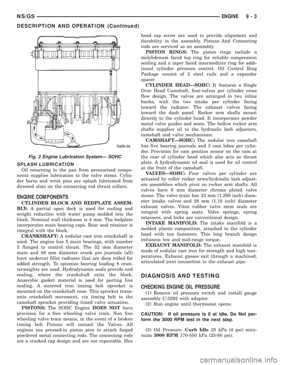
SPLASH LUBRICATION
Oil returning to the pan from pressurized compo-
nents supplies lubrication to the valve stems. Cylin-
der bores and wrist pins are splash lubricated from
directed slots on the connecting rod thrust collars.
ENGINE COMPONENTS
CYLINDER BLOCK AND BEDPLATE ASSEM-
B LY:A partial open deck is used for cooling and
weight reduction with water pump molded into the
block. Nominal wall thickness is 4 mm. The bedplate
incorporates main bearing caps. Rear seal retainer is
integral with the block.
CRANKSHAFT:A nodular cast iron crankshaft is
used. The engine has 5 main bearings, with number
3 flanged to control thrust. The 52 mm diameter
main and 48 mm diameter crank pin journals (all)
have undercut fillet radiuses that are deep rolled for
added strength. To optimize bearing loading 8 coun-
terweights are used. Hydrodynamic seals provide end
sealing, where the crankshaft exits the block.
Anaerobic gasket material is used for parting line
sealing. A sintered iron timing belt sprocket is
mounted on the crankshaft nose. This sprocket trans-
mits crankshaft movement, via timing belt to the
camshaft sprocket providing timed valve actuation.
PISTONS:The SOHC EngineDOES NOThave
provision for a free wheeling valve train. Non free
wheeling valve train means, in the event of a broken
timing belt Pistons will contact the Valves. All
engines use pressed-in piston pins to attach forged
powdered metal connecting rods. The connecting rods
are a cracked cap design and are not repairable. Hexhead cap screw are used to provide alignment and
durability in the assembly. Pistons And Connecting
rods are serviced as an assembly.
PISTON RINGS:The piston rings include a
molybdenum faced top ring for reliable compression
sealing and a taper faced intermediate ring for addi-
tional cylinder pressure control. Oil Control Ring
Package consist of 2 steel rails and a expander
spacer.
CYLINDER HEADÐSOHC:It features a Single
Over Head Camshaft, four-valves per cylinder cross
flow design. The valves are arranged in two inline
banks, with the two intake per cylinder facing
toward the radiator. The exhaust valves facing
toward the dash panel. Rocker arm shafts mount
directly to the cylinder head. It incorporates powder
metal valve guides and seats. The hollow rocker arm
shafts supplies oil to the hydraulic lash adjusters,
camshaft and valve mechanisms.
CAMSHAFTÐSOHC:The nodular iron camshaft
has five bearing journals and 3 cam lobes per cylin-
der. Provision for cam position sensor on the cam at
the rear of cylinder head which also acts as thrust
plate. A hydrodynamic oil seal is used for oil control
at the front of the camshaft.
VALVESÐSOHC:Four valves per cylinder are
actuated by roller rocker arms/hydraulic lash adjust-
ers assemblies which pivot on rocker arm shafts. All
valves have 6 mm diameter chrome plated valve
stems. The valve train has 33 mm (1.299 inch) diam-
eter intake valves and 28 mm (1.10 inch) diameter
exhaust valves. Viton rubber valve stem seals are
integral with spring seats. Valve springs, spring
retainers, and locks are conventional design.
INTAKE MANIFOLD:The intake manifold is a
molded plastic composition, attached to the cylinder
head with ten fasteners. This long branch design
enhances low and mid-range torque.
EXHAUST MANIFOLD:The exhaust manifold is
made of nodular cast iron for strength and high tem-
peratures. Exhaust gasses exit through a machined,
articulated joint connection to the exhaust pipe.
DIAGNOSIS AND TESTING
CHECKING ENGINE OIL PRESSURE
(1) Remove oil pressure switch and install gauge
assembly C-3292 with adaptor.
(2) Run engine until thermostat opens.
CAUTION: If oil pressure is 0 at idle, Do Not per-
form the 3000 RPM test in the next step.
(3) Oil Pressure:Curb Idle25 kPa (4 psi) mini-
mum3000 RPM170-550 kPa (25-80 psi).
Fig. 2 Engine Lubrication SystemÐ SOHC
NS/GSENGINE 9 - 3
DESCRIPTION AND OPERATION (Continued)
Page 1374 of 1938
Actual electric fuel timing (amount of advance) is
accomplished by the fuel timing solenoid mounted to
the bottom of the injection pump (Fig. 5). Fuel timing
will be adjusted by the PCM, which controls the fuel
timing solenoid.
An overflow valve is attached into the fuel return
line at the rear of the fuel injection pump (Fig. 4).
This valve serves two purposes. One is to ensure that
a certain amount of residual pressure is maintained
within the pump when the engine is switched off.
This will prevent the fuel timing mechanism within
the injection pump from returning to its zero posi-
tion. The other purpose is to allow excess fuel to be
returned to the fuel tank through the fuel return
line. The pressure values within this valve are preset
and can not be adjusted.
The fuel injection pump supplies high±pressure
fuel of approximately 45,000 kPa (6526 psi) to each
injector in precise metered amounts at the correct
time.
For mechanical injection pump timing, refer to
Fuel Injection Pump Timing in the Service Proce-
dures section of this group.
FUEL INJECTORS
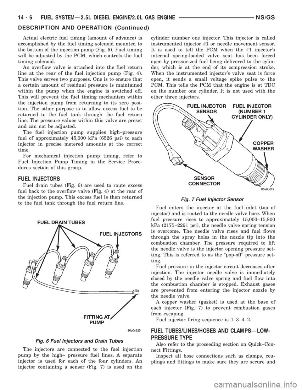
Fuel drain tubes (Fig. 6) are used to route excess
fuel back to the overflow valve (Fig. 4) at the rear of
the injection pump. This excess fuel is then returned
to the fuel tank through the fuel return line.
The injectors are connected to the fuel injection
pump by the high± pressure fuel lines. A separate
injector is used for each of the four cylinders. An
injector containing a sensor (Fig. 7) is used on thecylinder number one injector. This injector is called
instrumented injector #1 or needle movement sensor.
It is used to tell the PCM when the #1 injector's
internal spring-loaded valve seat has been forced
open by pressurized fuel being delivered to the cylin-
der, which is at the end of its compression stroke.
When the instrumented injector's valve seat is force
open, it sends a small voltage spike pulse to the
PCM. This tells the PCM that the engine is at TDC
on the number one cylinder. It is not used with the
other three injectors.
Fuel enters the injector at the fuel inlet (top of
injector) and is routed to the needle valve bore. When
fuel pressure rises to approximately 15,000±15,800
kPa (2175±2291 psi), the needle valve spring tension
is overcome. The needle valve rises and fuel flows
through the spray holes in the nozzle tip into the
combustion chamber. The pressure required to lift
the needle valve is the injector opening pressure set-
ting. This is referred to as the ªpop-offº pressure set-
ting.
Fuel pressure in the injector circuit decreases after
injection. The injector needle valve is immediately
closed by the needle valve spring and fuel flow into
the combustion chamber is stopped. Exhaust gases
are prevented from entering the injector nozzle by
the needle valve.
A copper washer (gasket) is used at the base of
each injector (Fig. 7) to prevent combustion gases
from escaping.
Fuel injector firing sequence is 1±3±4±2.
FUEL TUBES/LINES/HOSES AND CLAMPSÐLOW-
PRESSURE TYPE
Also refer to the proceeding section on Quick±Con-
nect Fittings.
Inspect all hose connections such as clamps, cou-
plings and fittings to make sure they are secure andFig. 6 Fuel Injectors and Drain Tubes
Fig. 7 Fuel Injector Sensor
14 - 6 FUEL SYSTEMÐ2.5L DIESEL ENGINE/2.0L GAS ENGINENS/GS
DESCRIPTION AND OPERATION (Continued)
Page 1378 of 1938
(7) Inspect the starter motor and starter solenoid
connections for tightness and corrosion.
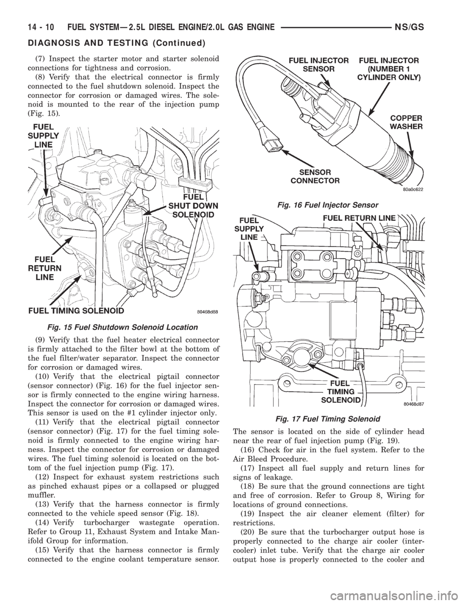
(8) Verify that the electrical connector is firmly
connected to the fuel shutdown solenoid. Inspect the
connector for corrosion or damaged wires. The sole-
noid is mounted to the rear of the injection pump
(Fig. 15).
(9) Verify that the fuel heater electrical connector
is firmly attached to the filter bowl at the bottom of
the fuel filter/water separator. Inspect the connector
for corrosion or damaged wires.
(10) Verify that the electrical pigtail connector
(sensor connector) (Fig. 16) for the fuel injector sen-
sor is firmly connected to the engine wiring harness.
Inspect the connector for corrosion or damaged wires.
This sensor is used on the #1 cylinder injector only.
(11) Verify that the electrical pigtail connector
(sensor connector) (Fig. 17) for the fuel timing sole-
noid is firmly connected to the engine wiring har-
ness. Inspect the connector for corrosion or damaged
wires. The fuel timing solenoid is located on the bot-
tom of the fuel injection pump (Fig. 17).
(12) Inspect for exhaust system restrictions such
as pinched exhaust pipes or a collapsed or plugged
muffler.
(13) Verify that the harness connector is firmly
connected to the vehicle speed sensor (Fig. 18).
(14) Verify turbocharger wastegate operation.
Refer to Group 11, Exhaust System and Intake Man-
ifold Group for information.
(15) Verify that the harness connector is firmly
connected to the engine coolant temperature sensor.The sensor is located on the side of cylinder head
near the rear of fuel injection pump (Fig. 19).
(16) Check for air in the fuel system. Refer to the
Air Bleed Procedure.
(17) Inspect all fuel supply and return lines for
signs of leakage.
(18) Be sure that the ground connections are tight
and free of corrosion. Refer to Group 8, Wiring for
locations of ground connections.
(19) Inspect the air cleaner element (filter) for
restrictions.
(20) Be sure that the turbocharger output hose is
properly connected to the charge air cooler (inter-
cooler) inlet tube. Verify that the charge air cooler
output hose is properly connected to the cooler and
Fig. 15 Fuel Shutdown Solenoid Location
Fig. 16 Fuel Injector Sensor
Fig. 17 Fuel Timing Solenoid
14 - 10 FUEL SYSTEMÐ2.5L DIESEL ENGINE/2.0L GAS ENGINENS/GS
DIAGNOSIS AND TESTING (Continued)
Page 1411 of 1938
FUEL INJECTION SYSTEMÐ2.5L DIESEL ENGINE
INDEX
page page
GENERAL INFORMATION
INTRODUCTION....................... 43
DESCRIPTION AND OPERATION
AIR CONDITIONING (A/C) CONTROLSÐ
PCM INPUTS........................ 47
AIR CONDITIONING RELAYÐPCM OUTPUT . . 48
BATTERY VOLTAGEÐPCM INPUT.......... 45
BOOST PRESSURE SENSOR............. 45
BRAKE SWITCHÐPCM INPUT............. 47
DATA LINK CONNECTORÐ
PCM INPUT AND OUTPUT.............. 47
DIESEL PCM RELAYÐPCM INPUT......... 48
ENGINE COOLANT GAUGEÐPCM OUTPUT . . 48
ENGINE COOLANT TEMPERATURE SENSORÐ
PCM INPUT......................... 46
ENGINE OIL PRESSURE GAUGEÐ
PCM OUTPUT........................ 48
ENGINE SPEED SENSORÐPCM INPUT..... 46
EXHAUST GAS RECIRCULATION (EGR)
SOLENOIDÐPCM OUTPUT............. 50
FIVE VOLT POWERÐPCM OUTPUT........ 48
FUEL INJECTOR SENSORÐGROUND...... 46
FUEL TIMING SOLENOIDÐPCM OUTPUT.... 48
GLOW PLUG LAMPÐPCM OUTPUT........ 48
GLOW PLUG RELAYÐPCM OUTPUT....... 49
GLOW PLUGS......................... 49
IGNITION CIRCUIT SENSEÐPCM INPUT.... 45
NEEDLE MOVEMENT OR INSTRUMENTED
FIRST INJECTORÐPCM INPUT.......... 45
POWER GROUND...................... 45
POWERTRAIN CONTROL MODULE (PCM) . . . 44
SENSOR RETURNÐPCM INPUT (ANALOG
GROUND)........................... 45SIGNAL GROUNDÐPCM INPUT........... 45
SPEED CONTROLÐPCM INPUTS.......... 48
SPEED CONTROLÐPCM OUTPUTS........ 48
START SIGNALÐPCM INPUT............. 45
TACHOMETERÐPCM OUTPUT............ 49
VEHICLE SPEED SENSORÐPCM INPUT.... 47
VEHICLE THEFT ALARM................. 45
DIAGNOSIS AND TESTING
BOOST PRESSURE SENSOR............. 53
DIAGNOSTIC TROUBLE CODES........... 53
DIESEL DIAGNOSTICS.................. 50
DIESEL PCM RELAY TEST............... 50
ENGINE COOLANT TEMPERATURE
SENSOR TEST....................... 50
ENGINE SPEED SENSOR TEST........... 50
GLOW PLUG RELAY TEST............... 51
GLOW PLUG TEST..................... 51
RELAYSÐOPERATION/TESTING........... 52
VEHICLE SPEED SENSOR TEST........... 53
REMOVAL AND INSTALLATION
A/C CLUTCH RELAY.................... 53
DIESEL PCM RELAY.................... 53
ENGINE COOLANT TEMPERATURE
SENSOR............................ 54
ENGINE SPEED SENSOR................ 53
GLOW PLUG RELAY.................... 55
GLOW PLUGS......................... 54
POWERTRAIN CONTROL MODULE (PCM) . . . 55
VEHICLE SPEED SENSOR............... 55
SPECIFICATIONS
GLOW PLUG CURRENT DRAW............ 56
TORQUE CHARTÐ2.5L DIESEL............ 57
GENERAL INFORMATION
INTRODUCTION
This section will cover components either regulated
or controlled by the Powertrain Control Module
(PCM). The fuel heater relay, fuel heater and fuel
gauge are not operated by the PCM. These compo-
nents are controlled by the ignition (key) switch. All
other fuel system electrical components necessary to
operate the engine are controlled or regulated by the
PCM. Refer to the following PCM description for
more information.
Certain fuel system component failures may cause
a no start, or prevent the engine from running. It is
important to know that the PCM has a featurewhere, if possible, it will ignore the failed sensor, set
a code related to the sensor, and operate the engine
in a ªLimp Homeº mode. When the PCM is operating
in a ªLimp Homeº mode, the Diesel Glow Plug lamp
on the instrument panel will be constantly illumi-
nated, and the engine will most likely have a notice-
able loss of performance. An example of this would be
an Accelerator Pedal Position Sensor failure, and in
that situation, the engine would run at a constant
1100 RPM, regardless of the actual position of the
pedal. This is the most extreme of the three ªLimp
Homeº modes.
In addition to indicating that the glow plugs are
hot enough to start combustion, the Glow Plug Lamp
is also used in the diagnosis of the PCM, and when
NS/GSFUEL SYSTEMÐ2.5L DIESEL ENGINE/2.0L GAS ENGINE 14 - 43
Page 1412 of 1938
illuminated constantly, it usually indicates a problem
has been detected somewhere within the fuel system.
The DRBIII scan tool is the best method for commu-
nicating with the PCM to diagnose faults within the
system.
DESCRIPTION AND OPERATION
POWERTRAIN CONTROL MODULE (PCM)
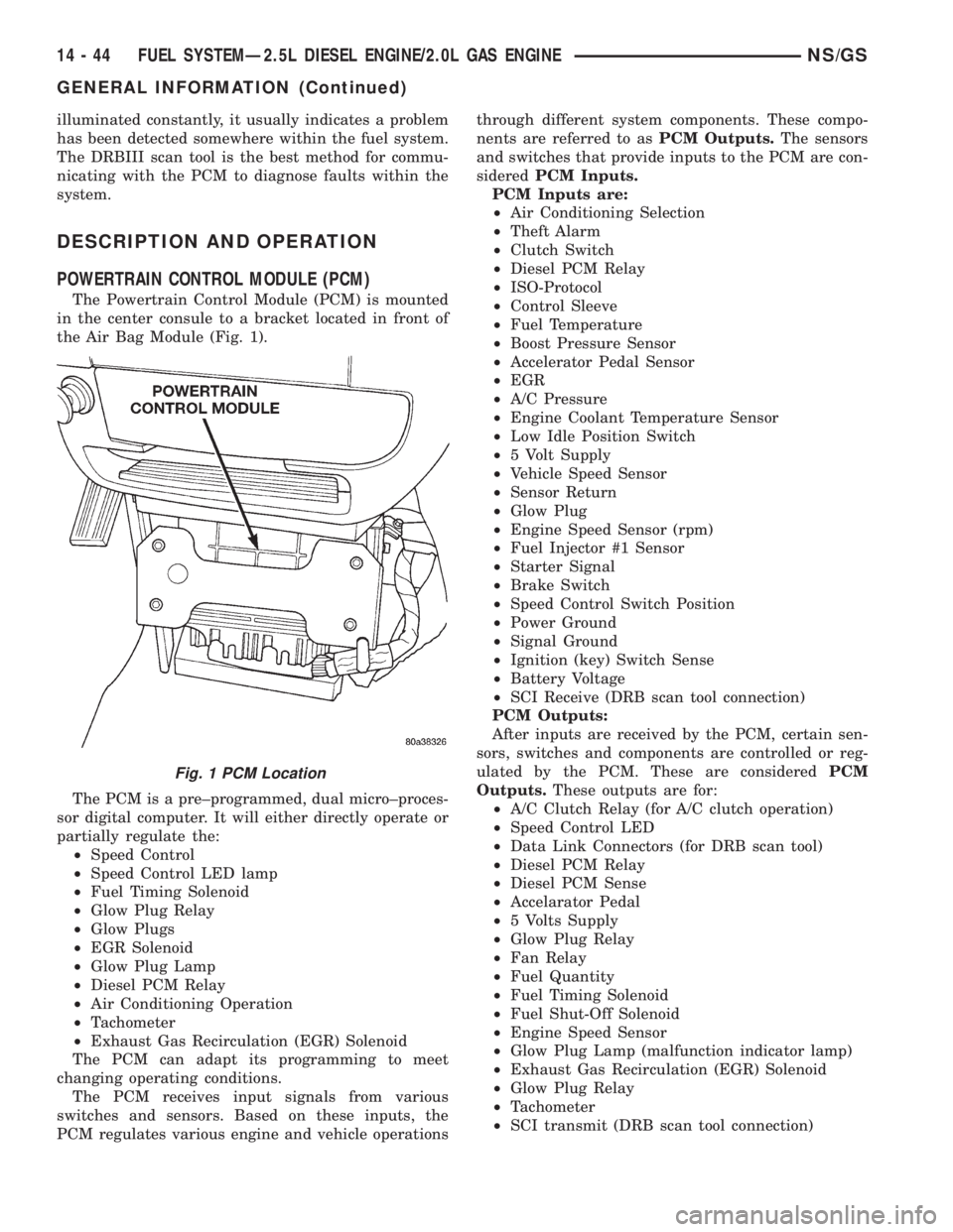
The Powertrain Control Module (PCM) is mounted
in the center consule to a bracket located in front of
the Air Bag Module (Fig. 1).
The PCM is a pre±programmed, dual micro±proces-
sor digital computer. It will either directly operate or
partially regulate the:
²Speed Control
²Speed Control LED lamp
²Fuel Timing Solenoid
²Glow Plug Relay
²Glow Plugs
²EGR Solenoid
²Glow Plug Lamp
²Diesel PCM Relay
²Air Conditioning Operation
²Tachometer
²Exhaust Gas Recirculation (EGR) Solenoid
The PCM can adapt its programming to meet
changing operating conditions.
The PCM receives input signals from various
switches and sensors. Based on these inputs, the
PCM regulates various engine and vehicle operationsthrough different system components. These compo-
nents are referred to asPCM Outputs.The sensors
and switches that provide inputs to the PCM are con-
sideredPCM Inputs.
PCM Inputs are:
²Air Conditioning Selection
²Theft Alarm
²Clutch Switch
²Diesel PCM Relay
²ISO-Protocol
²Control Sleeve
²Fuel Temperature
²Boost Pressure Sensor
²Accelerator Pedal Sensor
²EGR
²A/C Pressure
²Engine Coolant Temperature Sensor
²Low Idle Position Switch
²5 Volt Supply
²Vehicle Speed Sensor
²Sensor Return
²Glow Plug
²Engine Speed Sensor (rpm)
²Fuel Injector #1 Sensor
²Starter Signal
²Brake Switch
²Speed Control Switch Position
²Power Ground
²Signal Ground
²Ignition (key) Switch Sense
²Battery Voltage
²SCI Receive (DRB scan tool connection)
PCM Outputs:
After inputs are received by the PCM, certain sen-
sors, switches and components are controlled or reg-
ulated by the PCM. These are consideredPCM
Outputs.These outputs are for:
²A/C Clutch Relay (for A/C clutch operation)
²Speed Control LED
²Data Link Connectors (for DRB scan tool)
²Diesel PCM Relay
²Diesel PCM Sense
²Accelarator Pedal
²5 Volts Supply
²Glow Plug Relay
²Fan Relay
²Fuel Quantity
²Fuel Timing Solenoid
²Fuel Shut-Off Solenoid
²Engine Speed Sensor
²Glow Plug Lamp (malfunction indicator lamp)
²Exhaust Gas Recirculation (EGR) Solenoid
²Glow Plug Relay
²Tachometer
²SCI transmit (DRB scan tool connection)
Fig. 1 PCM Location
14 - 44 FUEL SYSTEMÐ2.5L DIESEL ENGINE/2.0L GAS ENGINENS/GS
GENERAL INFORMATION (Continued)