1996 CHRYSLER VOYAGER engine
[x] Cancel search: enginePage 1172 of 1938
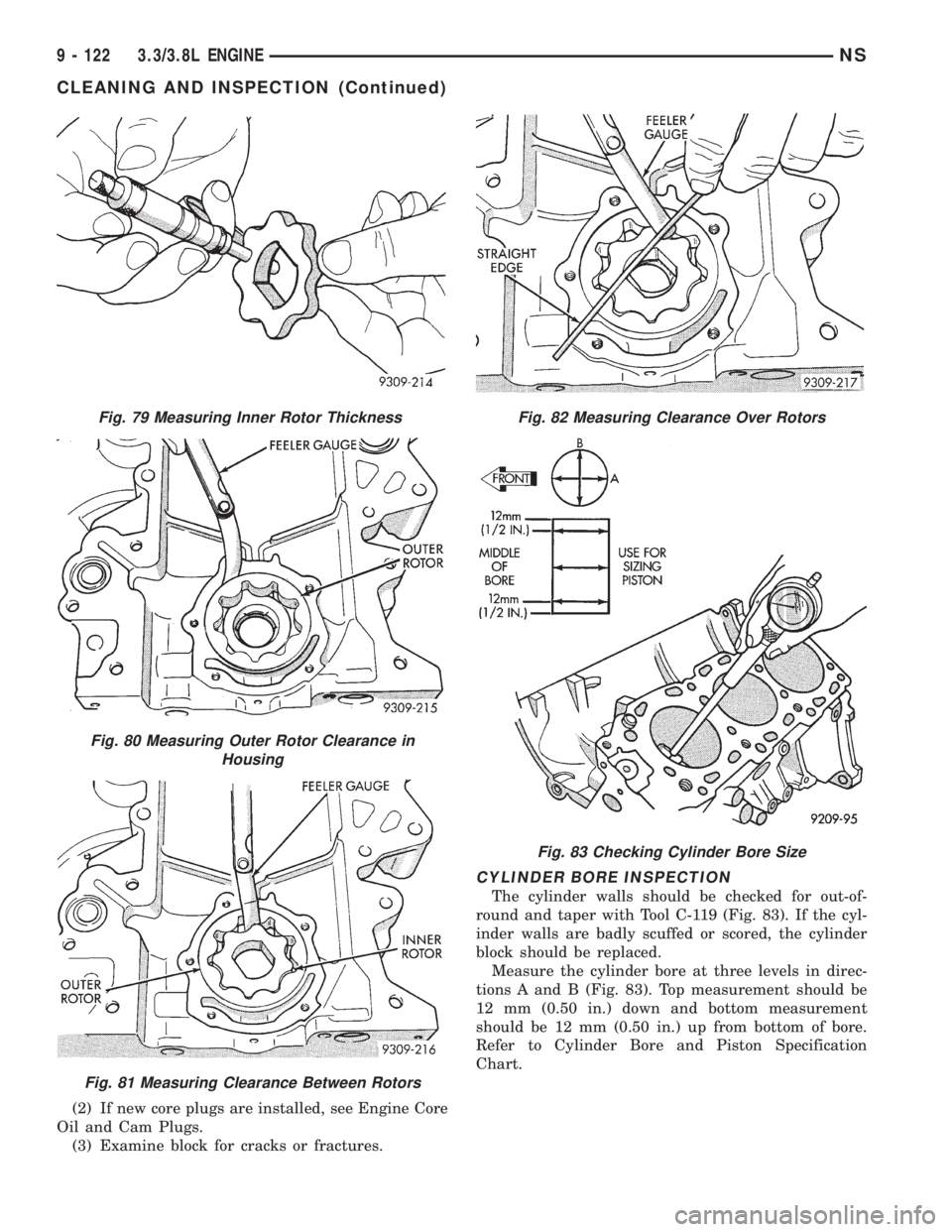
(2) If new core plugs are installed, see Engine Core
Oil and Cam Plugs.
(3) Examine block for cracks or fractures.
CYLINDER BORE INSPECTION
The cylinder walls should be checked for out-of-
round and taper with Tool C-119 (Fig. 83). If the cyl-
inder walls are badly scuffed or scored, the cylinder
block should be replaced.
Measure the cylinder bore at three levels in direc-
tions A and B (Fig. 83). Top measurement should be
12 mm (0.50 in.) down and bottom measurement
should be 12 mm (0.50 in.) up from bottom of bore.
Refer to Cylinder Bore and Piston Specification
Chart.
Fig. 79 Measuring Inner Rotor Thickness
Fig. 80 Measuring Outer Rotor Clearance in
Housing
Fig. 81 Measuring Clearance Between Rotors
Fig. 82 Measuring Clearance Over Rotors
Fig. 83 Checking Cylinder Bore Size
9 - 122 3.3/3.8L ENGINENS
CLEANING AND INSPECTION (Continued)
Page 1173 of 1938
ADJUSTMENTS
ENGINE MOUNTS
ENGINE MOUNT INSULATOR ADJUSTMENT
(1) Remove the load on the engine motor mounts
by carefully supporting the engine and transmission
assembly with a floor jack.
(2) Loosen the right engine mount insulator verti-
cal fastener and the fore and aft fasteners, and the
front engine mount bracket to front crossmember
screws.
(3) Pry the engine right or left as required to
achieve the proper drive shaft assembly length. Refer
to Group 2, Suspension and Driveshafts for drive-
shaft identification and related assembly length mea-
suring.
(4) Tighten engine mounts and fasteners in the
following order:
(a) Right engine mount insulator vertical bolts
to 102 N´m (75 ft. lbs.) and the fore and aft bolts to
150 N´m (110 ft. lbs.).
(b) Front engine mount screws to 54 N´m (40 ft.
lbs.) the clearance between the snubbers and the
engine should be 2 mm (0.078 inch.) each side.
(c) Left engine mount through bolt to 75 N´m (55
ft. lbs.).
(5) Recheck driveshaft length.
SPECIFICATIONS
3.3/3.8L ENGINE
Type.........................60É V-6 Engine
Bore±3.3L..................93.0 mm (3.66 in.)
Bore±3.8L.................96.0 mm (3.779 in.)
Stroke±3.3L...............81.0 mm (3.188 in.)
Stroke±3.8L...............87.0 mm (3.425 in.)
Compression Ratio±3.3L.................8.9:1
Compression Ratio±3.8L.................9.6:1
Displacement±3.3L..........3.3L (201 Cubic in.)
Displacement±3.8L..........3.8L (231 Cubic in.)
Brake Horsepower±3.3L........158 @ 4850 RPM
Brake Horsepower±3.8L........180 @ 4400 RPM
Torque±3.3L............203 lb. ft. @ 3600 RPM
Torque±3.8L............240 lb. ft. @ 3600 RPM
Firing Order....................1±2±3±4±5±6
Compression Pressure.Refer to Engine Performance
in Standard Service Procedures.
Cylinder Number (Front to Rear)
Front Bank...........................2,4,6
Rear Bank............................1,3,6
Cylinder Block
Cylinder Bore (Standard)±3.3L.........93.0 mm
(3.66 in.)
Cylinder Bore (Standard)±3.8L.........96.0 mm
(3.779 in.)
Out-of-Round (Max.)........0.076 mm (0.003 in.)
Taper (Max.)..............0.051 mm (0.002 in.)
Cylinder Bore Oversize (Max.).........0.508 mm
(0.020 in.)
Tappet Bore Diameter.....22.9896 - 23.0099 mm
(0.9051 - 0.9059 in.)
Pistons
Type Material.......Aluminum Alloy Tin Coated
Clearance at Size Location......0.025 - 0.057 mm
(0.001 - 0.0022 in.)
Weight (Standard Only)±3.3L......38165 grams
(13.439460.1764 oz.)
Weight (Standard Only)±3.8L......43865 grams
(15.450160.1764 oz.)
Pistons for Service..............Standard Only
Piston Pins
Type .......................Press Fit in Rod
(Serviced as an Assembly)
Diameter.........................22.88 mm
(0.9009 - 0.9007 in.)
Length±3.3L................67.25 - 67.75 mm
(2.648 - 2.667 in.)
Lenth±3.8L.................71.25 - 71.75 mm
(2.805 - 2.824 in.)
Clearance in Piston @ 70É......0.006 - 0.019 mm
(0.0002 - 0.0007 in.)
Clearance in Rod................(Interference)
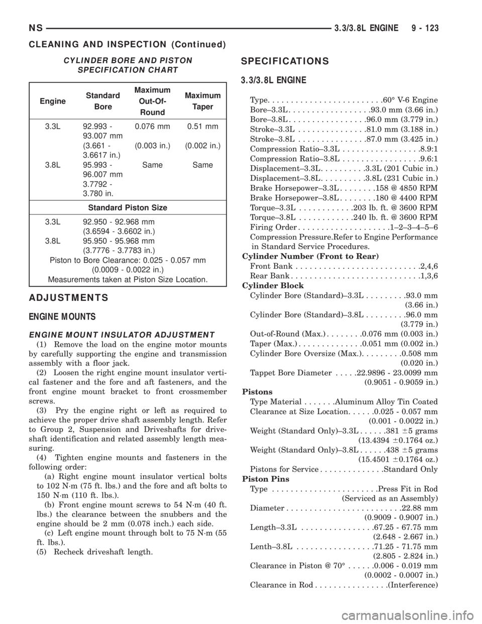
CYLINDER BORE AND PISTON
SPECIFICATION CHART
EngineStandard
BoreMaximum
Out-Of-
RoundMaximum
Taper
3.3L 92.993 -
93.007 mm0.076 mm 0.51 mm
(3.661 -
3.6617 in.)(0.003 in.) (0.002 in.)
3.8L 95.993 -
96.007 mmSame Same
3.7792 -
3.780 in.
Standard Piston Size
3.3L 92.950 - 92.968 mm
(3.6594 - 3.6602 in.)
3.8L 95.950 - 95.968 mm
(3.7776 - 3.7783 in.)
Piston to Bore Clearance: 0.025 - 0.057 mm
(0.0009 - 0.0022 in.)
Measurements taken at Piston Size Location.
NS3.3/3.8L ENGINE 9 - 123
CLEANING AND INSPECTION (Continued)
Page 1174 of 1938
Piston Rings
Number of Rings..........................3
Compression.............................2
Oil Control..............................1
Oil Ring Type . . .3±Piece, Steel Rail, Chrome Face
Piston Ring Gap
Top & 2nd Compression ing.......0.30 - 0.55 mm
(0.0118 - 0.0217 in.)
Oil Control (Steel Rails).........0.25 - 1.00 mm
(0.0098 - 0.0394 in.)
Service Rings
Ring Gap±Compression........0.300 - 0.550 mm
(0.0118 - 0.0217 in.)
Ring Gap±Oil Control..........0.250 - 1.00 mm
(0.0098 - 0.0394 in.)
Piston Ring Side Clearance
Top & 2nd Compression Rings . . .0.030 - 0.095 mm
(0.0012 - 0.0037 in.)
Oil Ring (Steel Rails)..........0.014 - 0.226 mm
(0.0005 - 0.0089 in.)
Piston Ring Width
Compression Rings.............1.46 - 1.50 mm
(0.0575 - 0.0591 in.)
Oil Ring (Steel Rails)................0.510 mm
(0.0201 in.)
Connecting Rods
Bearing Type.........Aluminum Lead (Bimetal)
Bearing Clearance............0.019 - 0.065 mm
(0.00075 - 0.0026 in.)
Max. Allowable..........0.076 mm (0.003 in.)
Side Clearance..............0.127 - 0.381 mm
(0.005 - 0.015 in.)
Crankshaft
Type......................Cast Nodular Iron
Bearing Type.........Aluminum Lead (Bimetal)
Thrust Location.................No. 2 Bearing
Connecting Rod
Journal Diameter..........53.950 - 53.975 mm
(2.124 - 2.125 in.)
Main Bearing Diametrical
Clearance No. 1- 4............0.011 - 0.059 mm
(0.0043 - 0.0023 in.)
Max. Allowable..........0.102 mm (0.004 in.)
End Play.....0.09 - 0.24 mm (0.0036 - 0.0095 in.)
Max. Allowable..........0.381 mm (0.015 in.)
Main Bearing Journals
Diameter.................64.013 - 63.993 mm
(2.5202 - 2.5195 in.)
Out-of-Round (Max.)........0.025 mm (0.001 in.)
Taper (Max.)..............0.025 mm (0.001 in.)
Connecting Rod Journals
Diameter.................58.005 - 57.979 mm
(2.2837 - 2.2827 in.)
Out-of-Round (Max.)........0.025 mm (0.001 in.)
Taper (Max.)..............0.025 mm (0.001 in.)Camshaft
Drive...............................Chain
Bearings.................Steel Backed Babbitt
Number.................................4
Diametrical Clearance.........0.025 - 0.101 mm
(0.001 - 0.004 in.)
Max. Allowable..........0.127 mm (0.005 in.)
Thrust Taken By.................Thrust Plate
End Play...................0.127 - 0.304 mm
(0.005 - 0.012 in.)
Max. Allowable..........0.304 mm (0.012 in.)
Camshaft Journals
Bearing Journal
Diameter No. 1............50.724 - 50.775 mm
(1.997 - 1.999 in.)
Bearing Journal
Diameter No. 2............50.317 - 50.368 mm
(1.9809 - 1.9829 in.)
Bearing Journal
Diameter No. 3............49.936 - 49.987 mm
(1.9659 - 1.9679 in.)
Bearing Journal
Diameter No. 4............49.530 - 49.581 mm
(1.9499 - 1.9520 in.)
Camshaft Bearings
Diameter No. 1.............50.825 - 50.800 mm
(2.0009 - 1.9999 in.)
Diameter No. 2.............50.419 - 50.393 mm
(1.9849 - 1.9839 in.)
Diameter No. 3.............50.038 - 50.013 mm
(1.9699 - 1.9690 in.)
Diameter No. 4.............49.632 - 49.606 mm
(1.954 - 1.9529 in.)
Oil Clearance..............0.0254 - 0.0762 mm
(0.001 - 0.003 in.)
Valve Timing Exhaust Valve
Closes (ATC)...........................12É
Opens (BBC)...........................48É
Duration.............................240É
Valve Timing Intake Valve
Closes (BTDC)..........................58É
Opens.................................2É
Duration.............................240É
Valve Overlap..........................14É
Timing Chain
Number of Links.........................64
Pitch............................0.375 inch
Width...........................0.750 inch
Hydraulic Tappets
Type .......................Roller Hydraulic
Body Diameter...............22.95 - 22.96 mm
(0.9035 - 0.9040 in.)
Clearance in Block..............0.02 - 0.06 mm
(0.0007 - 0.0024 in.)
9 - 124 3.3/3.8L ENGINENS
SPECIFICATIONS (Continued)
Page 1175 of 1938
Service Tappets Available........Std., 0.025 mm
(0.001), 0.20 mm (0.008 in.),
0.762 mm (0.030 in.)
Cylinder Head
Gasket Thickness (Compressed)........1.78 mm
(0.070 in.)
Cylinder Head Valve Seat
Angle±Intake and Exhaust...........45-45.5É
Runout (Max)............0.0762 mm (0.003 in.)
Width (Finish)±Intake...........1.75 - 2.25 mm
(0.069 - 0.088 in.)
Width (Finish)±Exhaust.........1.50 - 2.00 mm
(0.057 - 0.078 in.)
Valve Guides
Type..................Powdered Metal Inserts
Guide Bore Diameter...........7.975 - 8.00 mm
(0.314 - 0.315 in.)
ValvesÐIntake
Face Angle...........................44.5É
Head Diameter..............45.5 mm (1.79 in.)
Length (Overall)..........127.005 - 128.036 mm
(5.000 - 5.041 in.)
Minimum Valve Length
After Tip Grinding...................124.892
(4.916 in.)
Lift (Zero Lash)...........10.16 mm (0.400 in.)
Stem Diameter (Standard)......7.935 - 7.953 mm
(0.312 - 0.313 in.)
Valve Tip Height (From
Cylinder Head Surface)......49.541 - 51.271 mm
(1.950 - 2.018 in.)
Stem-to-Guide Clearance.......0.025 - 0.095 mm
(0.001 - 0.003 in.)
Max. Allowable (Rocking Method). . . .0.247 mm
(0.010 in.)
Valves for Service
(Oversize Stem Diameters).......Std., 0.015 mm
(0.005 in.), 0.40 mm (0.015 in.),
0.80 mm (0.030 in.)
ValvesÐExhaust
Face Angle.............................45É
Head Diameter.............37.5 mm (1.476 in.)
Length Overall..............127.825 - 128.465
(5.032 - 5.058 in.)
Minimum Valve Length
After Tip Grinding.......125.512 mm (4.941 in.)
Lift (Zero Lash)............10.16 mm (0.40 in.)
Valve Tip Height (From
Cylinder Head Surface)......49.541 - 51.271 mm
(1.950 - 2.018 in.)
Stem Diameter (Standar).......7.906 - 7.924 mm
(0.3112 - 0.3119 in.)
Stem to Guide Clearance.......0.051 - 0.175 mm
(0.002 - 0.006 in.)Max. Allowable (Rocking Method)......0.414 mm
(0.016 in.)
Valves for Service (Oversize
Stem Diameters)......Std., 0.015 mm (0.005 in.),
0.40 mm (0.015 in.), 0.80 mm (0.030 in.)
Valve Springs
Free Length (Approx.).......48.5 mm (1.909 in.)
Wire Diameter.............4.75 mm (0.187 in.)
Number of Coils.........................6.8
Spring Tension (Valve Closed).......95-100lbs.
@ 1.57 in.
Spring Tension (Valve Open).......207 - 229 lbs.
@ 1.169 in.
Installed Height (Spring
Seat to Bottom of Retainer)......41.2 - 42.7 mm
(1.622 - 1.681 in.)
Oil Pump
Pump Type...............Rotary Full Pressure
Clearance Over Rotors
(Inner & Outer Max.)........0.10 mm (0.004 in.)
Cover Out-of-Flat (Max.).....0.025 mm (0.001 in.)
Inner Rotor Thickness (Min.) . .7.64 mm (0.301 in.)
Outer Rotor Thickness (Min.) . .7.64 mm (0.301 in.)
Outer Rotor Diameter (Min.) .79.95 mm (3.148 in.)
Outer Rotor Clearance.......0.39 mm (0.015 in.)
Tip Clearance Between Rotors (Max.). . . .0.20 mm
(0.008 in.)
Oil Pressure
Minimum Pressure at Idle (Engine
Fully Warmed Up)*...........34.47 kPa (5 psi)
At 3000 rpm.........205 - 551 kPa (30 - 80 psi)
Oil Filter Bypass Valve Setting......62-103kPa
(9 - 15 psi)
Oil Filter Type.....................Full Flow
Oil Pressure Switch Actuating
Pressure (Min.)...........14-28kPa(2 - 4 psi)
CAUTION: * If pressure is ZERO at curb Idle, DO
NOT run engine at 3,000 rpm.
NS3.3/3.8L ENGINE 9 - 125
SPECIFICATIONS (Continued)
Page 1176 of 1938
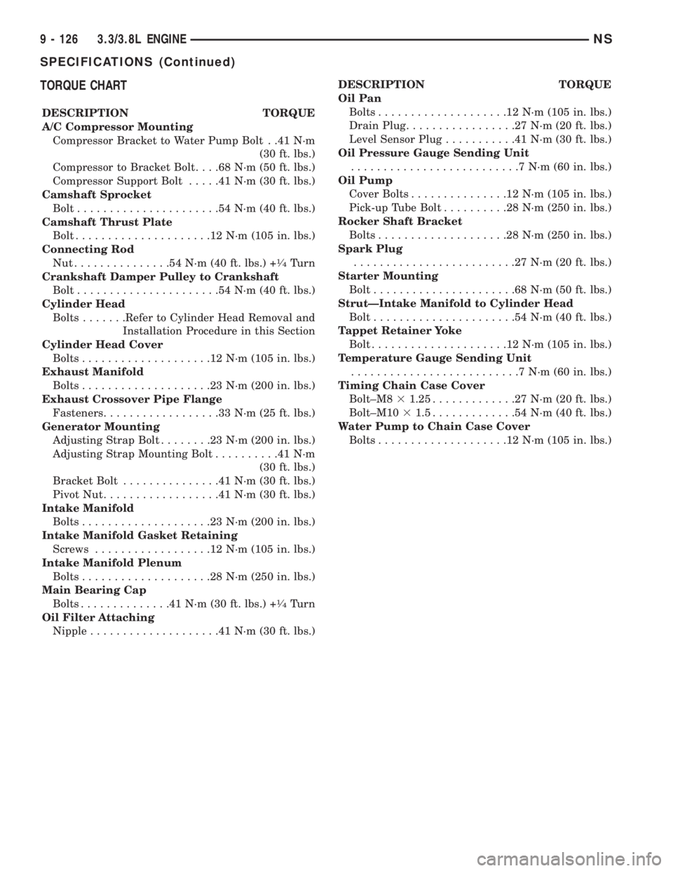
TORQUE CHART
DESCRIPTION TORQUE
A/C Compressor Mounting
Compressor Bracket to Water Pump Bolt . .41 N´m
(30 ft. lbs.)
Compressor to Bracket Bolt. . . .68 N´m (50 ft. lbs.)
Compressor Support Bolt.....41N´m(30ft.lbs.)
Camshaft Sprocket
Bolt......................54N´m(40ft.lbs.)
Camshaft Thrust Plate
Bolt.....................12N´m(105 in. lbs.)
Connecting Rod
Nut...............54N´m(40ft.lbs.) +
1¤4Turn
Crankshaft Damper Pulley to Crankshaft
Bolt......................54N´m(40ft.lbs.)
Cylinder Head
Bolts.......Refer to Cylinder Head Removal and
Installation Procedure in this Section
Cylinder Head Cover
Bolts....................12N´m(105 in. lbs.)
Exhaust Manifold
Bolts....................23N´m(200 in. lbs.)
Exhaust Crossover Pipe Flange
Fasteners..................33N´m(25ft.lbs.)
Generator Mounting
Adjusting Strap Bolt........23N´m(200 in. lbs.)
Adjusting Strap Mounting Bolt..........41N´m
(30 ft. lbs.)
Bracket Bolt...............41N´m(30ft.lbs.)
Pivot Nut..................41N´m(30ft.lbs.)
Intake Manifold
Bolts....................23N´m(200 in. lbs.)
Intake Manifold Gasket Retaining
Screws..................12N´m(105 in. lbs.)
Intake Manifold Plenum
Bolts....................28N´m(250 in. lbs.)
Main Bearing Cap
Bolts..............41N´m(30ft.lbs.) +
1¤4Turn
Oil Filter Attaching
Nipple....................41N´m(30ft.lbs.)DESCRIPTION TORQUE
Oil Pan
Bolts....................12N´m(105 in. lbs.)
Drain Plug.................27N´m(20ft.lbs.)
Level Sensor Plug...........41N´m(30ft.lbs.)
Oil Pressure Gauge Sending Unit
..........................7N´m(60in.lbs.)
Oil Pump
Cover Bolts...............12N´m(105 in. lbs.)
Pick-up Tube Bolt..........28N´m(250 in. lbs.)
Rocker Shaft Bracket
Bolts....................28N´m(250 in. lbs.)
Spark Plug
.........................27N´m(20ft.lbs.)
Starter Mounting
Bolt......................68N´m(50ft.lbs.)
StrutÐIntake Manifold to Cylinder Head
Bolt......................54N´m(40ft.lbs.)
Tappet Retainer Yoke
Bolt.....................12N´m(105 in. lbs.)
Temperature Gauge Sending Unit
..........................7N´m(60in.lbs.)
Timing Chain Case Cover
Bolt±M831.25.............27N´m(20ft.lbs.)
Bolt±M1031.5.............54N´m(40ft.lbs.)
Water Pump to Chain Case Cover
Bolts....................12N´m(105 in. lbs.)
9 - 126 3.3/3.8L ENGINENS
SPECIFICATIONS (Continued)
Page 1177 of 1938
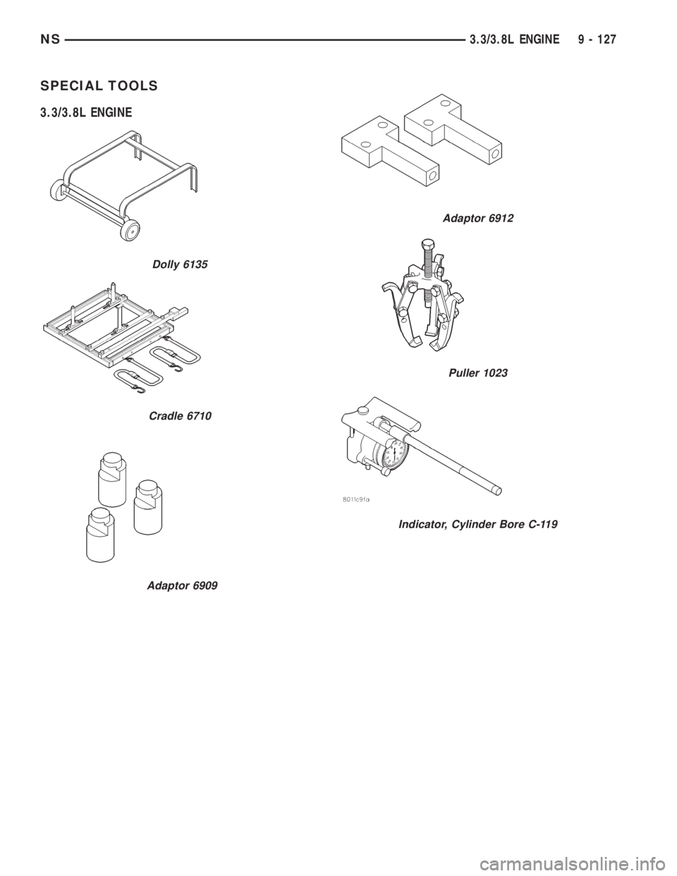
SPECIAL TOOLS
3.3/3.8L ENGINE
Adaptor 6909
Dolly 6135
Cradle 6710
Adaptor 6912
Puller 1023
Indicator, Cylinder Bore C-119
NS3.3/3.8L ENGINE 9 - 127
Page 1178 of 1938
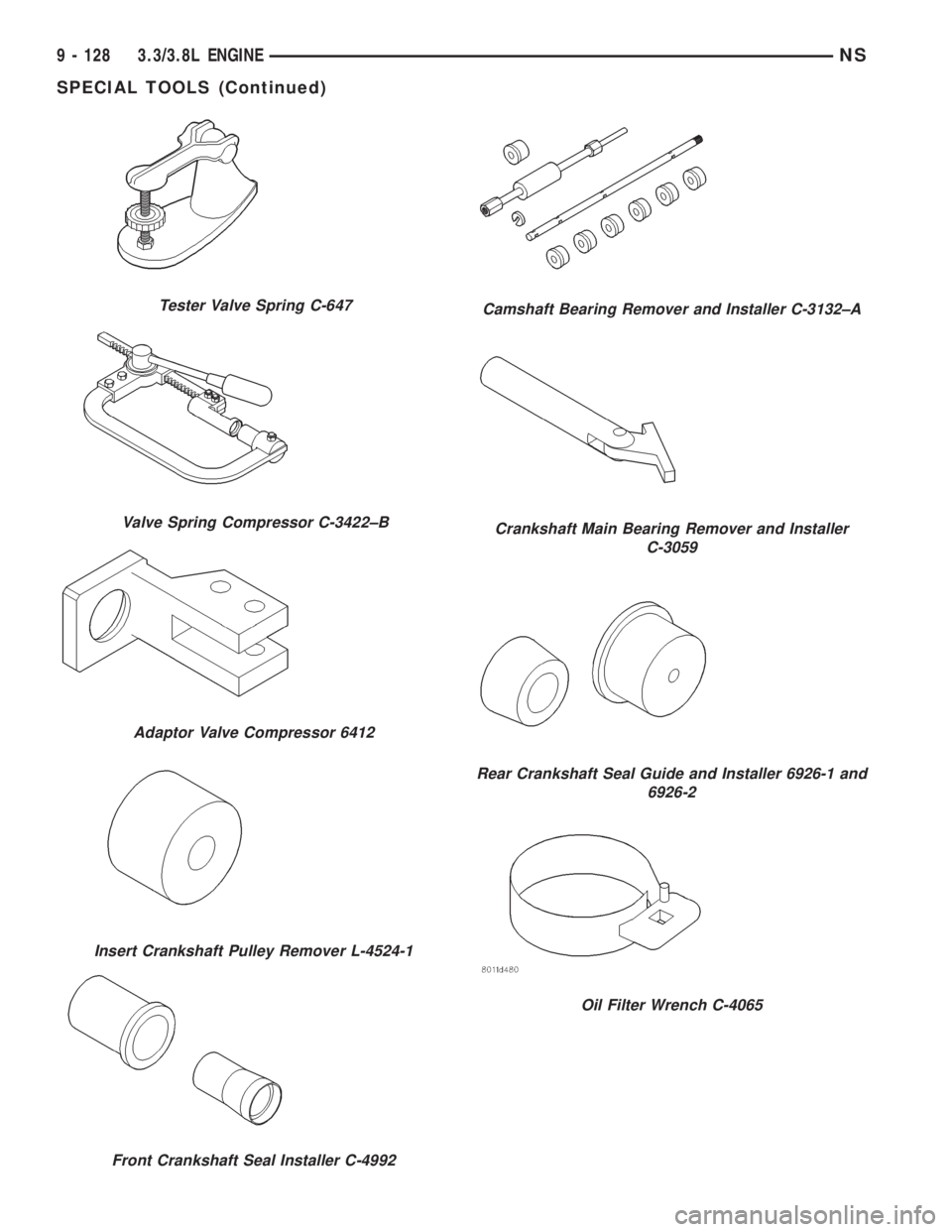
Tester Valve Spring C-647
Valve Spring Compressor C-3422±B
Adaptor Valve Compressor 6412
Insert Crankshaft Pulley Remover L-4524-1
Front Crankshaft Seal Installer C-4992
Camshaft Bearing Remover and Installer C-3132±A
Crankshaft Main Bearing Remover and Installer
C-3059
Rear Crankshaft Seal Guide and Installer 6926-1 and
6926-2
Oil Filter Wrench C-4065
9 - 128 3.3/3.8L ENGINENS
SPECIAL TOOLS (Continued)
Page 1179 of 1938
ENGINE
CONTENTS
page page
2.0L SOHC ENGINE...................... 12.5L VM DIESEL....................... 40
2.0L SOHC ENGINE
INDEX
page page
DESCRIPTION AND OPERATION
ENGINE COMPONENTS.................. 3
ENGINE IDENTIFICATION................. 1
ENGINE LUBRICATION SYSTEM............ 2
GENERAL SPECIFICATION................ 2
DIAGNOSIS AND TESTING
CHECKING ENGINE OIL PRESSURE........ 3
SERVICE PROCEDURES
CRANKSHAFT END PLAY................. 6
CYLINDER BORE AND PISTON SIZING....... 4
FITTING CONNECTING RODS.............. 5
FITTING CRANKSHAFT BEARINGS.......... 6
FITTING PISTON RINGS.................. 4
REMOVAL AND INSTALLATION
CAMSHAFT OIL SEAL................... 12
CAMSHAFT............................ 7
CRANKSHAFT OIL SEALÐREAR........... 20
CRANKSHAFT......................... 21
CYLINDER HEAD COVER................. 6
CYLINDER HEAD....................... 10
FRONT CRANKSHAFT OIL SEAL........... 18
OILFILTER ........................... 24
OIL FILTER ADAPTER................... 24OILPAN .............................. 17
OIL PUMP............................ 25
PISTON AND CONNECTING ROD.......... 25
ROCKER ARM/HYDRAULIC LASH ADJUSTER . . 8
SPARK PLUG TUBE...................... 7
TIMING BELT COVER................... 11
TIMING BELT SYSTEM.................. 13
VALVE SEALS AND SPRINGS IN VEHICLE . . . 10
VIBRATION DAMPER.................... 28
DISASSEMBLY AND ASSEMBLY
OIL PUMP............................ 29
VALVE SERVICE WITH THE CYLINDER HEAD
REMOVED.......................... 29
CLEANING AND INSPECTION
CYLINDER BLOCK AND BORE............ 34
CYLINDER HEAD AND CAMSHAFT
JOURNALS.......................... 32
OIL PUMP............................ 32
SPECIFICATIONS
ENGINE 2.0L SOHC..................... 34
TORQUE CHART 2.0L SOHC.............. 36
SPECIAL TOOLS
ENGINE 2.0L SOHC..................... 36
DESCRIPTION AND OPERATION
ENGINE IDENTIFICATION
The engine identification number is located on the
left rear of the cylinder block behind starter (Fig. 1).
Fig. 1 Engine Identification SOHC
NS/GSENGINE 9 - 1