1996 CHRYSLER VOYAGER engine
[x] Cancel search: enginePage 1156 of 1938
CRANKSHAFT DAMPER
REMOVAL
(1) Disconnect negative cable from battery.
(2) Raise vehicle on hoist.
(3) Remove right wheel and inner splash shield.
(4) Remove drive belt. Refer to Group 7, Cooling
System for procedure.
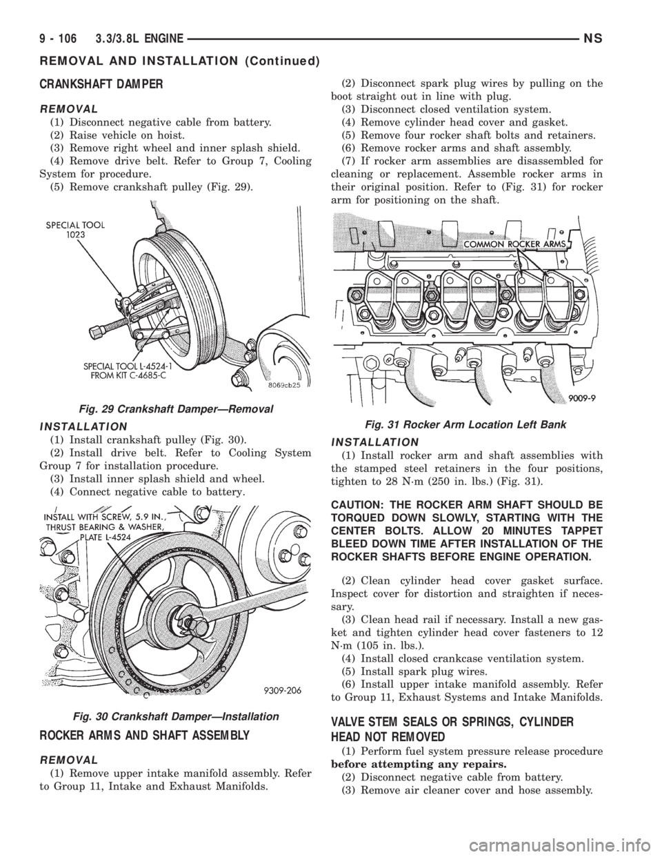
(5) Remove crankshaft pulley (Fig. 29).
INSTALLATION
(1) Install crankshaft pulley (Fig. 30).
(2) Install drive belt. Refer to Cooling System
Group 7 for installation procedure.
(3) Install inner splash shield and wheel.
(4) Connect negative cable to battery.
ROCKER ARMS AND SHAFT ASSEMBLY
REMOVAL
(1) Remove upper intake manifold assembly. Refer
to Group 11, Intake and Exhaust Manifolds.(2) Disconnect spark plug wires by pulling on the
boot straight out in line with plug.
(3) Disconnect closed ventilation system.
(4) Remove cylinder head cover and gasket.
(5) Remove four rocker shaft bolts and retainers.
(6) Remove rocker arms and shaft assembly.
(7) If rocker arm assemblies are disassembled for
cleaning or replacement. Assemble rocker arms in
their original position. Refer to (Fig. 31) for rocker
arm for positioning on the shaft.
INSTALLATION
(1) Install rocker arm and shaft assemblies with
the stamped steel retainers in the four positions,
tighten to 28 N´m (250 in. lbs.) (Fig. 31).
CAUTION: THE ROCKER ARM SHAFT SHOULD BE
TORQUED DOWN SLOWLY, STARTING WITH THE
CENTER BOLTS. ALLOW 20 MINUTES TAPPET
BLEED DOWN TIME AFTER INSTALLATION OF THE
ROCKER SHAFTS BEFORE ENGINE OPERATION.
(2) Clean cylinder head cover gasket surface.
Inspect cover for distortion and straighten if neces-
sary.
(3) Clean head rail if necessary. Install a new gas-
ket and tighten cylinder head cover fasteners to 12
N´m (105 in. lbs.).
(4) Install closed crankcase ventilation system.
(5) Install spark plug wires.
(6) Install upper intake manifold assembly. Refer
to Group 11, Exhaust Systems and Intake Manifolds.
VALVE STEM SEALS OR SPRINGS, CYLINDER
HEAD NOT REMOVED
(1) Perform fuel system pressure release procedure
before attempting any repairs.
(2) Disconnect negative cable from battery.
(3) Remove air cleaner cover and hose assembly.
Fig. 29 Crankshaft DamperÐRemoval
Fig. 30 Crankshaft DamperÐInstallation
Fig. 31 Rocker Arm Location Left Bank
9 - 106 3.3/3.8L ENGINENS
REMOVAL AND INSTALLATION (Continued)
Page 1157 of 1938
(4) Remove upper intake manifold. Refer to Group
11, Exhaust System and Intake Manifolds for proce-
dure.
(5) Remove cylinder head covers and spark plugs.
(6) Remove electrical connector from ignition coils.
(7) Using suitable socket and flex handle at crank-
shaft pulley retaining screw, turn engine so the num-
ber 1 piston is at Top Dead Center on the
compression stroke.
(8) Remove rocker arms with rocker shaft and
install a dummy shaft. The rocker arms should not
be disturbed and left on shaft.
(9) With air hose attached to spark plug adapter
installed in number 1 spark plug hole, apply 90 to
100 psi air pressure (620.5 to 689 kPa). This is to
hold valves in place while servicing components.
(10) Using Tool C-4682 or equivalent, compress
valve spring and remove retainer valve locks and
valve spring.
(11) The intake valve stem seals should be pushed
firmly and squarely over the valve guide using the
valve stem as guide.Do Not Forceseal against top
of guide. When installing the valve retainer locks,
compress the springonly enoughto install the
locks.
CAUTION: Do not pinch seal between retainer and
top of valve guide.
(12) Follow the same procedure on the remaining 5
cylinders using the firing sequence 1-2-3-4-5-6.Make
sure piston in cylinder is at TDC on the valve
spring that is being covered.
(13) Remove spark plug adapter tool.
(14) Remove dummy shaft and install rocker shaft
assembly and tighten screws to 28 N´m (250 in. lbs.).
(15) Install cylinder head covers tighten screws to
14 N´m (120 in. lbs.) and electrical connector to igni-
tion coils.
(16) Install Intake Manifold. Refer to Group 11,
Exhaust System and Intake Manifold for procedure.
(17) Connect negative cable to battery.
CYLINDER HEAD COVER
REMOVAL
NOTE: The cylinder head cover can be either an
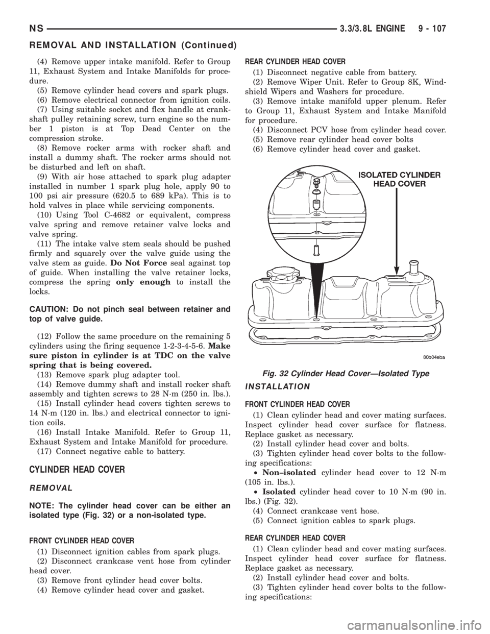
isolated type (Fig. 32) or a non-isolated type.
FRONT CYLINDER HEAD COVER
(1) Disconnect ignition cables from spark plugs.
(2) Disconnect crankcase vent hose from cylinder
head cover.
(3) Remove front cylinder head cover bolts.
(4) Remove cylinder head cover and gasket.REAR CYLINDER HEAD COVER
(1) Disconnect negative cable from battery.
(2) Remove Wiper Unit. Refer to Group 8K, Wind-
shield Wipers and Washers for procedure.
(3) Remove intake manifold upper plenum. Refer
to Group 11, Exhaust System and Intake Manifold
for procedure.
(4) Disconnect PCV hose from cylinder head cover.
(5) Remove rear cylinder head cover bolts
(6) Remove cylinder head cover and gasket.
INSTALLATION
FRONT CYLINDER HEAD COVER
(1) Clean cylinder head and cover mating surfaces.
Inspect cylinder head cover surface for flatness.
Replace gasket as necessary.
(2) Install cylinder head cover and bolts.
(3) Tighten cylinder head cover bolts to the follow-
ing specifications:
²Non±isolatedcylinder head cover to 12 N´m
(105 in. lbs.).
²Isolatedcylinder head cover to 10 N´m (90 in.
lbs.) (Fig. 32).
(4) Connect crankcase vent hose.
(5) Connect ignition cables to spark plugs.
REAR CYLINDER HEAD COVER
(1) Clean cylinder head and cover mating surfaces.
Inspect cylinder head cover surface for flatness.
Replace gasket as necessary.
(2) Install cylinder head cover and bolts.
(3) Tighten cylinder head cover bolts to the follow-
ing specifications:
Fig. 32 Cylinder Head CoverÐIsolated Type
NS3.3/3.8L ENGINE 9 - 107
REMOVAL AND INSTALLATION (Continued)
Page 1158 of 1938
²Non±isolatedcylinder head cover to 12 N´m
(105 in. lbs.).
²Isolatedcylinder head cover to 10 N´m (90 in.
lbs.) (Fig. 32).
(4) Connect PCV hose from cylinder head cover.
(5) Install intake manifold upper plenum. Refer to
Group 11, Exhaust System and Intake Manifold for
procedure.
(6) Install Wiper Unit. Refer to Group 8K, Wind-
shield Wipers and Washers for procedure.
(7) Connect negative cable to battery.
CYLINDER HEAD
REMOVAL
(1) Drain cooling system. Refer to Group 7, Cooling
System for procedure and disconnect negative cable
from battery.
(2) Remove upper and lower intake manifolds.
Refer to Group 11, Exhaust System and Intake Man-
ifold.
WARNING: INTAKE MANIFOLD GASKET IS MADE
OF VERY THIN METAL AND MAY CAUSE PER-
SONAL INJURY, HANDLE WITH CARE.
(3) Disconnect coil wires, sending unit wire, heater
hoses and bypass hose.
(4) Remove PCV system hoses, evaporation control
system hose and cylinder head covers.
(5) Remove exhaust manifolds.
(6) Remove rocker arm and shaft assemblies.
Remove push rods andmark positions to ensure
installation in original locations.
(7) Remove the 9 head bolts from each cylinder
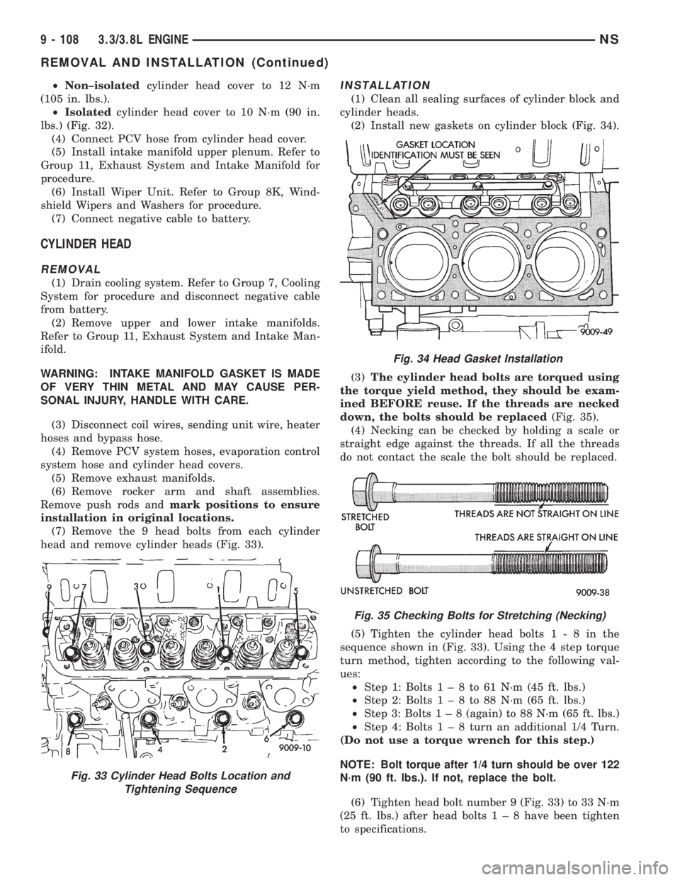
head and remove cylinder heads (Fig. 33).
INSTALLATION
(1) Clean all sealing surfaces of cylinder block and
cylinder heads.
(2) Install new gaskets on cylinder block (Fig. 34).
(3)The cylinder head bolts are torqued using
the torque yield method, they should be exam-
ined BEFORE reuse. If the threads are necked
down, the bolts should be replaced(Fig. 35).
(4) Necking can be checked by holding a scale or
straight edge against the threads. If all the threads
do not contact the scale the bolt should be replaced.
(5) Tighten the cylinder head bolts1-8inthe
sequence shown in (Fig. 33). Using the 4 step torque
turn method, tighten according to the following val-
ues:
²Step 1: Bolts1±8to61N´m(45ft.lbs.)
²Step 2: Bolts1±8to88N´m(65ft.lbs.)
²Step 3: Bolts1±8(again) to 88 N´m (65 ft. lbs.)
²Step 4: Bolts1±8turn an additional 1/4 Turn.
(Do not use a torque wrench for this step.)
NOTE: Bolt torque after 1/4 turn should be over 122
N´m (90 ft. lbs.). If not, replace the bolt.
(6) Tighten head bolt number 9 (Fig. 33) to 33 N´m
(25 ft. lbs.) after head bolts1±8have been tighten
to specifications.
Fig. 33 Cylinder Head Bolts Location and
Tightening Sequence
Fig. 34 Head Gasket Installation
Fig. 35 Checking Bolts for Stretching (Necking)
9 - 108 3.3/3.8L ENGINENS
REMOVAL AND INSTALLATION (Continued)
Page 1159 of 1938
(7) Inspect push rods and replace worn or bent
rods.
(8) Install push rods, rocker arm and shaft assem-
blies with the stamped steel retainers in the four
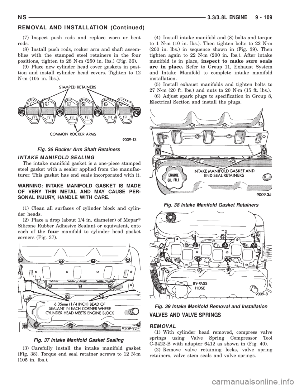
positions, tighten to 28 N´m (250 in. lbs.) (Fig. 36).
(9) Place new cylinder head cover gaskets in posi-
tion and install cylinder head covers. Tighten to 12
N´m (105 in. lbs.).
INTAKE MANIFOLD SEALING
The intake manifold gasket is a one-piece stamped
steel gasket with a sealer applied from the manufac-
turer. This gasket has end seals incorporated with it.
WARNING: INTAKE MANIFOLD GASKET IS MADE
OF VERY THIN METAL AND MAY CAUSE PER-
SONAL INJURY, HANDLE WITH CARE.
(1) Clean all surfaces of cylinder block and cylin-
der heads.
(2) Place a drop (about 1/4 in. diameter) of Mopart
Silicone Rubber Adhesive Sealant or equivalent, onto
each of thefourmanifold to cylinder head gasket
corners (Fig. 37).
(3) Carefully install the intake manifold gasket
(Fig. 38). Torque end seal retainer screws to 12 N´m
(105 in. lbs.).(4) Install intake manifold and (8) bolts and torque
to 1 N´m (10 in. lbs.). Then tighten bolts to 22 N´m
(200 in. lbs.) in sequence shown in (Fig. 39). Then
tighten again to 22 N´m (200 in. lbs.). After intake
manifold is in place,inspect to make sure seals
are in place.Refer to Group 11, Exhaust System
and Intake Manifold to complete intake manifold
installation.
(5) Install exhaust manifolds and tighten bolts to
27 N´m (20 ft. lbs.) and nuts to 20 N´m (15 ft. lbs.).
(6) Adjust spark plugs to specification in Group 8,
Electrical Section and install the plugs.
VALVES AND VALVE SPRINGS
REMOVAL
(1) With cylinder head removed, compress valve
springs using Valve Spring Compressor Tool
C-3422-B with adapter 6412 as shown in (Fig. 40).
(2) Remove valve retaining locks, valve spring
retainers, valve stem seals and valve springs.
Fig. 36 Rocker Arm Shaft Retainers
Fig. 37 Intake Manifold Gasket Sealing
Fig. 38 Intake Manifold Gasket Retainers
Fig. 39 Intake Manifold Removal and Installation
NS3.3/3.8L ENGINE 9 - 109
REMOVAL AND INSTALLATION (Continued)
Page 1160 of 1938
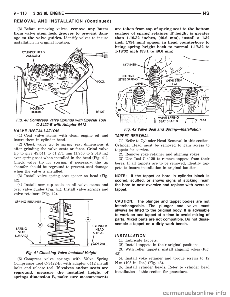
(3) Before removing valves,remove any burrs
from valve stem lock grooves to prevent dam-
age to the valve guides.Identify valves to insure
installation in original location.
VALVE INSTALLATION
(1) Coat valve stems with clean engine oil and
insert them in cylinder head.
(2) Check valve tip to spring seat dimensions A
after grinding the valve seats or faces. Grind valve
tip to give 49.541 to 51.271 mm (1.950 to 2.018 in.)
over spring seat when installed in the head (Fig. 41).
Check valve tip for scoring, if necessary, the tip
chamfer should be reground to prevent seal damage
when the valve is installed.
(3) Install valve spring seat spacer on head (Fig.
42).
(4) Install new cup seals on all valve stems and
over valve guides (Fig. 41). Install valve springs and
valve retainers (Fig. 42).
(5) Compress valve springs with Valve Spring
Compressor Tool C-3422-B, with adapter 6412 install
locks and release tool.If valves and/or seats are
reground, measure the installed height of
springs dimension B, make sure measurementsare taken from top of spring seat to the bottom
surface of spring retainer. If height is greater
than 1-19/32 inches, (40.6 mm), install a 1/32
inch (.794 mm) spacer in head counterbore to
bring spring height back to normal 1-17/32 to
1-19/32 inch (39.1 to 40.6 mm).TAPPET REMOVAL
(1) Refer to Cylinder Head Removal in this section.
Cylinder Head must be removed to gain access to
tappets for service.
(2) Remove yoke retainer and aligning yokes.
(3) Use Tool C-4129 to remove tappets from their
bores. If all tappets are to be removed, identify tap-
pets to insure installation in original location.
NOTE: If the tappet or bore in cylinder block is
scored, scuffed, or shows signs of sticking, ream
the bore to next oversize and replace with oversize
tappet.
CAUTION: The plunger and tappet bodies are not
interchangeable. The plunger and valve must
always be fitted to the original body. It is advisable
to work on one tappet at a time to avoid mixing of
parts. Mixed parts are not compatible. Do not disas-
semble a tappet on a dirty work bench.
INSTALLATION
(1) Lubricate tappets.
(2) Install tappets in their original positions.
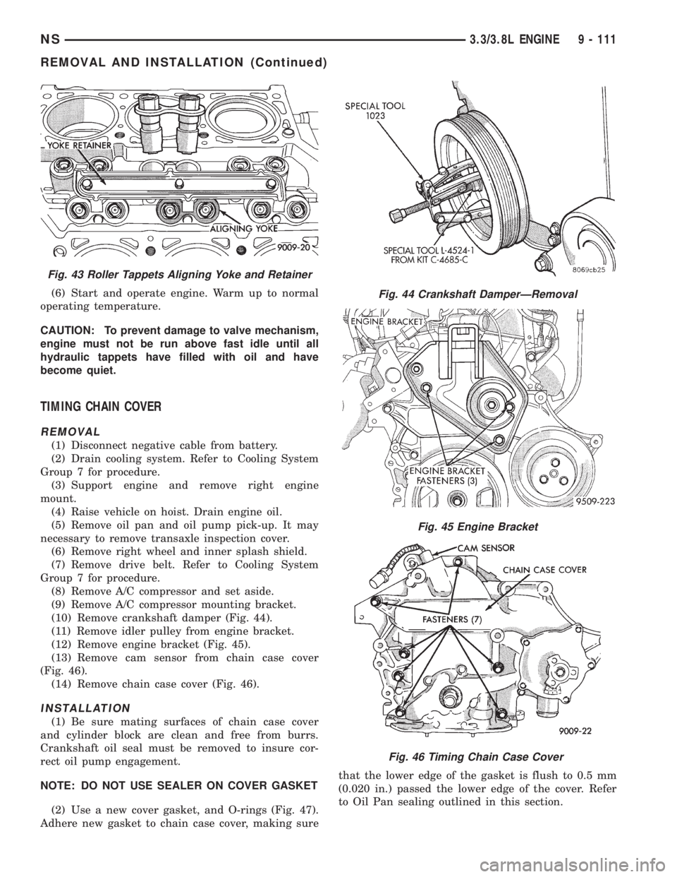
(3) With roller tappets, install aligning yokes (Fig.
43).
(4) Install yoke retainer and torque screws to 12
N´m (105 in. lbs.) (Fig. 43).
(5) Install cylinder heads. Refer to cylinder head
installation of this section for procedure.
Fig. 40 Compress Valve Springs with Special Tool
C-3422-B with Adapter 6412
Fig. 41 Checking Valve Installed Height
Fig. 42 Valve Seal and SpringÐInstallation
9 - 110 3.3/3.8L ENGINENS
REMOVAL AND INSTALLATION (Continued)
Page 1161 of 1938
(6) Start and operate engine. Warm up to normal
operating temperature.
CAUTION: To prevent damage to valve mechanism,
engine must not be run above fast idle until all
hydraulic tappets have filled with oil and have
become quiet.
TIMING CHAIN COVER
REMOVAL
(1) Disconnect negative cable from battery.
(2) Drain cooling system. Refer to Cooling System
Group 7 for procedure.
(3) Support engine and remove right engine
mount.
(4) Raise vehicle on hoist. Drain engine oil.
(5) Remove oil pan and oil pump pick-up. It may
necessary to remove transaxle inspection cover.
(6) Remove right wheel and inner splash shield.
(7) Remove drive belt. Refer to Cooling System
Group 7 for procedure.
(8) Remove A/C compressor and set aside.
(9) Remove A/C compressor mounting bracket.
(10) Remove crankshaft damper (Fig. 44).
(11) Remove idler pulley from engine bracket.
(12) Remove engine bracket (Fig. 45).
(13) Remove cam sensor from chain case cover
(Fig. 46).
(14) Remove chain case cover (Fig. 46).
INSTALLATION
(1) Be sure mating surfaces of chain case cover
and cylinder block are clean and free from burrs.
Crankshaft oil seal must be removed to insure cor-
rect oil pump engagement.
NOTE: DO NOT USE SEALER ON COVER GASKET
(2) Use a new cover gasket, and O-rings (Fig. 47).
Adhere new gasket to chain case cover, making surethat the lower edge of the gasket is flush to 0.5 mm
(0.020 in.) passed the lower edge of the cover. Refer
to Oil Pan sealing outlined in this section.
Fig. 43 Roller Tappets Aligning Yoke and Retainer
Fig. 44 Crankshaft DamperÐRemoval
Fig. 45 Engine Bracket
Fig. 46 Timing Chain Case Cover
NS3.3/3.8L ENGINE 9 - 111
REMOVAL AND INSTALLATION (Continued)
Page 1162 of 1938
(3) Rotate crankshaft so that the oil pump drive
flats are vertical.
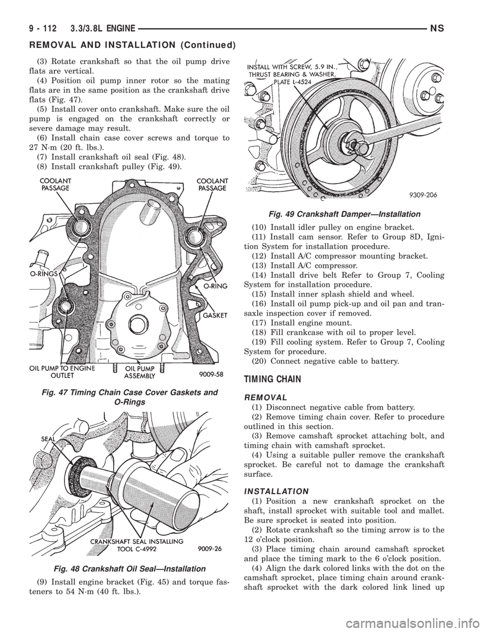
(4) Position oil pump inner rotor so the mating
flats are in the same position as the crankshaft drive
flats (Fig. 47).
(5) Install cover onto crankshaft. Make sure the oil
pump is engaged on the crankshaft correctly or
severe damage may result.
(6) Install chain case cover screws and torque to
27 N´m (20 ft. lbs.).
(7) Install crankshaft oil seal (Fig. 48).
(8) Install crankshaft pulley (Fig. 49).
(9) Install engine bracket (Fig. 45) and torque fas-
teners to 54 N´m (40 ft. lbs.).(10) Install idler pulley on engine bracket.
(11) Install cam sensor. Refer to Group 8D, Igni-
tion System for installation procedure.
(12) Install A/C compressor mounting bracket.
(13) Install A/C compressor.
(14) Install drive belt Refer to Group 7, Cooling
System for installation procedure.
(15) Install inner splash shield and wheel.
(16) Install oil pump pick-up and oil pan and tran-
saxle inspection cover if removed.
(17) Install engine mount.
(18) Fill crankcase with oil to proper level.
(19) Fill cooling system. Refer to Group 7, Cooling
System for procedure.
(20) Connect negative cable to battery.
TIMING CHAIN
REMOVAL
(1) Disconnect negative cable from battery.
(2) Remove timing chain cover. Refer to procedure
outlined in this section.
(3) Remove camshaft sprocket attaching bolt, and
timing chain with camshaft sprocket.
(4) Using a suitable puller remove the crankshaft
sprocket. Be careful not to damage the crankshaft
surface.
INSTALLATION
(1) Position a new crankshaft sprocket on the
shaft, install sprocket with suitable tool and mallet.
Be sure sprocket is seated into position.
(2) Rotate crankshaft so the timing arrow is to the
12 o'clock position.
(3) Place timing chain around camshaft sprocket
and place the timing mark to the 6 o'clock position.
(4) Align the dark colored links with the dot on the
camshaft sprocket, place timing chain around crank-
shaft sprocket with the dark colored link lined up
Fig. 47 Timing Chain Case Cover Gaskets and
O-Rings
Fig. 48 Crankshaft Oil SealÐInstallation
Fig. 49 Crankshaft DamperÐInstallation
9 - 112 3.3/3.8L ENGINENS
REMOVAL AND INSTALLATION (Continued)
Page 1163 of 1938
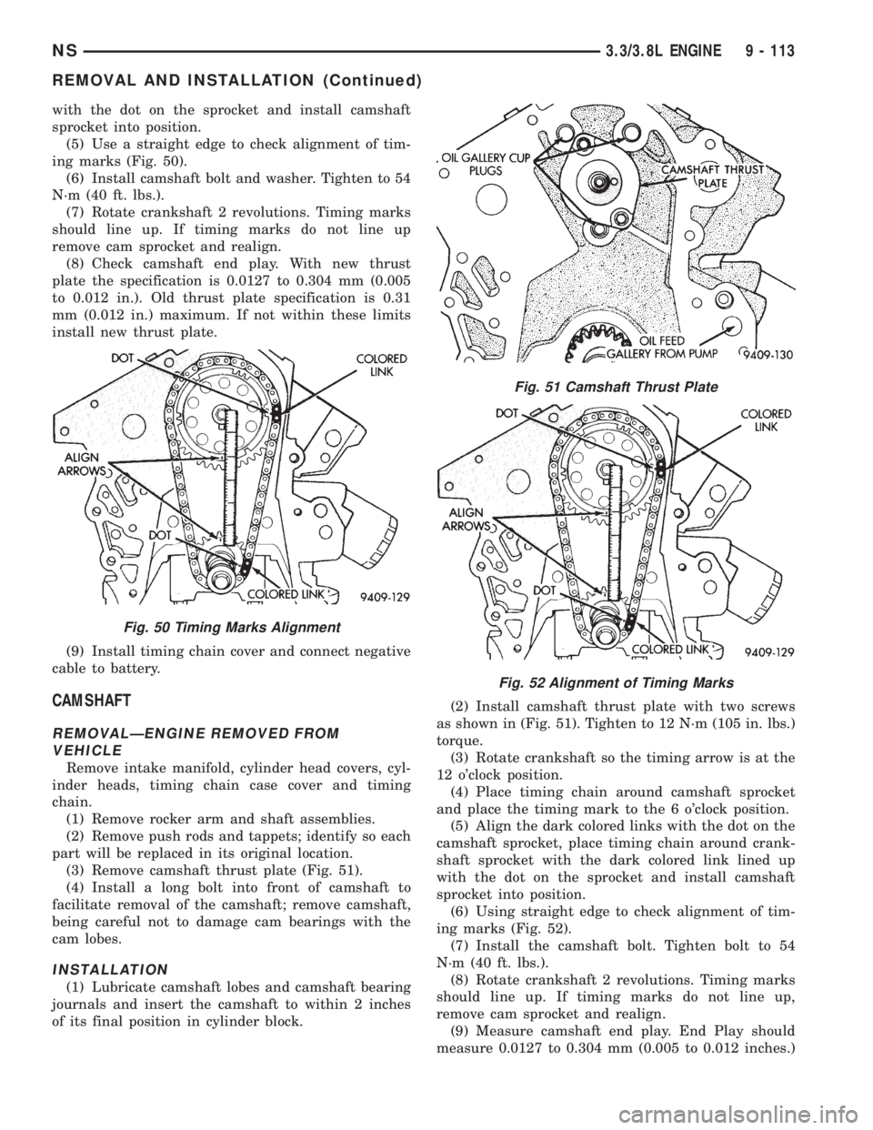
with the dot on the sprocket and install camshaft
sprocket into position.
(5) Use a straight edge to check alignment of tim-
ing marks (Fig. 50).
(6) Install camshaft bolt and washer. Tighten to 54
N´m (40 ft. lbs.).
(7) Rotate crankshaft 2 revolutions. Timing marks
should line up. If timing marks do not line up
remove cam sprocket and realign.
(8) Check camshaft end play. With new thrust
plate the specification is 0.0127 to 0.304 mm (0.005
to 0.012 in.). Old thrust plate specification is 0.31
mm (0.012 in.) maximum. If not within these limits
install new thrust plate.
(9) Install timing chain cover and connect negative
cable to battery.
CAMSHAFT
REMOVALÐENGINE REMOVED FROM
VEHICLE
Remove intake manifold, cylinder head covers, cyl-
inder heads, timing chain case cover and timing
chain.
(1) Remove rocker arm and shaft assemblies.
(2) Remove push rods and tappets; identify so each
part will be replaced in its original location.
(3) Remove camshaft thrust plate (Fig. 51).
(4) Install a long bolt into front of camshaft to
facilitate removal of the camshaft; remove camshaft,
being careful not to damage cam bearings with the
cam lobes.
INSTALLATION
(1) Lubricate camshaft lobes and camshaft bearing
journals and insert the camshaft to within 2 inches
of its final position in cylinder block.(2) Install camshaft thrust plate with two screws
as shown in (Fig. 51). Tighten to 12 N´m (105 in. lbs.)
torque.
(3) Rotate crankshaft so the timing arrow is at the
12 o'clock position.
(4) Place timing chain around camshaft sprocket
and place the timing mark to the 6 o'clock position.
(5) Align the dark colored links with the dot on the
camshaft sprocket, place timing chain around crank-
shaft sprocket with the dark colored link lined up
with the dot on the sprocket and install camshaft
sprocket into position.
(6) Using straight edge to check alignment of tim-
ing marks (Fig. 52).
(7) Install the camshaft bolt. Tighten bolt to 54
N´m (40 ft. lbs.).
(8) Rotate crankshaft 2 revolutions. Timing marks
should line up. If timing marks do not line up,
remove cam sprocket and realign.
(9) Measure camshaft end play. End Play should
measure 0.0127 to 0.304 mm (0.005 to 0.012 inches.)
Fig. 50 Timing Marks Alignment
Fig. 51 Camshaft Thrust Plate
Fig. 52 Alignment of Timing Marks
NS3.3/3.8L ENGINE 9 - 113
REMOVAL AND INSTALLATION (Continued)