Page 1124 of 1938

CYLINDER HEAD
REMOVAL
(1) Remove timing belt and camshaft sprockets.
See Timing Belt in this section for procedures.
(2) Remove cylinder head covers and rocker arms
and shafts. Refer to procedure outlined in this sec-
tion.
(3) Remove intake manifolds. Refer to Intake and
Exhaust Manifolds, Group 11.
(4) Remove distributor.
(5) Remove exhaust manifolds and cross over Refer
to Intake and Exhaust Manifolds, Group 11.
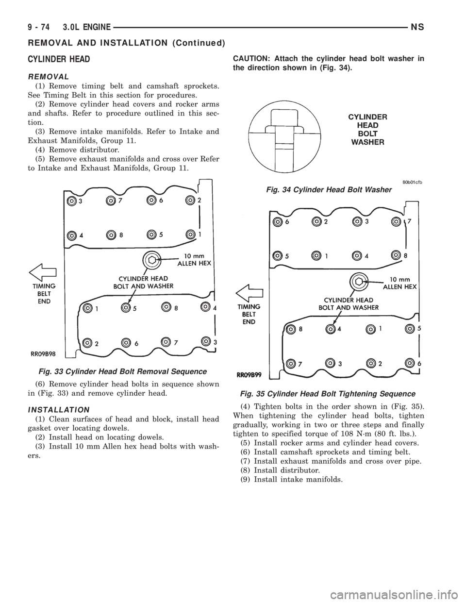
(6) Remove cylinder head bolts in sequence shown
in (Fig. 33) and remove cylinder head.
INSTALLATION
(1) Clean surfaces of head and block, install head
gasket over locating dowels.
(2) Install head on locating dowels.
(3) Install 10 mm Allen hex head bolts with wash-
ers.CAUTION: Attach the cylinder head bolt washer in
the direction shown in (Fig. 34).
(4) Tighten bolts in the order shown in (Fig. 35).
When tightening the cylinder head bolts, tighten
gradually, working in two or three steps and finally
tighten to specified torque of 108 N´m (80 ft. lbs.).
(5) Install rocker arms and cylinder head covers.
(6) Install camshaft sprockets and timing belt.
(7) Install exhaust manifolds and cross over pipe.
(8) Install distributor.
(9) Install intake manifolds.
Fig. 33 Cylinder Head Bolt Removal Sequence
Fig. 34 Cylinder Head Bolt Washer
Fig. 35 Cylinder Head Bolt Tightening Sequence
9 - 74 3.0L ENGINENS
REMOVAL AND INSTALLATION (Continued)
Page 1125 of 1938
TIMING BELT
REMOVAL
(1) Mark belt running direction for installation
(Fig. 38).
(2) Loosen timing belt tensioner bolt (Fig. 40) and
remove timing belt.
(3) Remove crankshaft sprocket flange shield (Fig.
36).
Fig. 36 Timing Belt System
Fig. 37 Timing Belt Covers
NS3.0L ENGINE 9 - 75
REMOVAL AND INSTALLATION (Continued)
Page 1126 of 1938

CAMSHAFT SPROCKETS
To remove camshaft sprockets
1. Hold camshaft sprocket with Spanner Tool
MB-990775 loosen and remove bolt and washer (Fig.
39).
2. Remove camshaft sprocket from camshaft.
To install camshaft sprockets
3. Place camshaft sprocket on camshaft.
4. Install bolt and washer to camshaft. Using
Spanner Tool MB-990775 hold camshaft sprocket and
torque bolt to 95 N´m (70 ft. lbs.) (Fig. 39).
TIMING BELT TENSIONER
(1) Install timing belt tensioner and tensioner
spring.
(2) Hook spring upper end to water pump pin and
lower end to tensioner bracket with hook out (Fig.
40).
(3) Turn timing belt tensioner counterclockwise
full travel in adjustment slot and tighten bolt to tem-
porarily hold this position (Fig. 41).
INSTALLATIONÐTIMING BELT
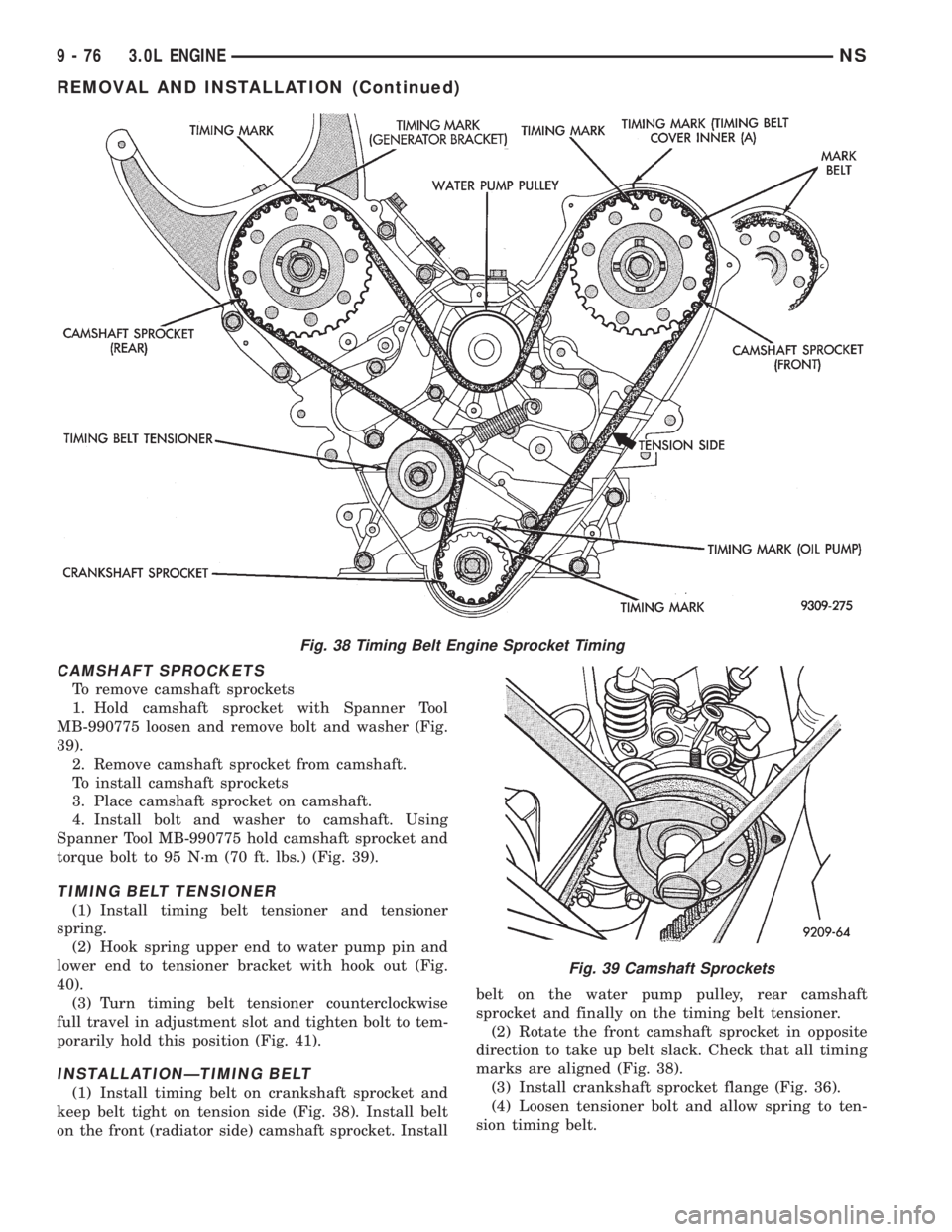
(1) Install timing belt on crankshaft sprocket and
keep belt tight on tension side (Fig. 38). Install belt
on the front (radiator side) camshaft sprocket. Installbelt on the water pump pulley, rear camshaft
sprocket and finally on the timing belt tensioner.
(2) Rotate the front camshaft sprocket in opposite
direction to take up belt slack. Check that all timing
marks are aligned (Fig. 38).
(3) Install crankshaft sprocket flange (Fig. 36).
(4) Loosen tensioner bolt and allow spring to ten-
sion timing belt.
Fig. 38 Timing Belt Engine Sprocket Timing
Fig. 39 Camshaft Sprockets
9 - 76 3.0L ENGINENS
REMOVAL AND INSTALLATION (Continued)
Page 1127 of 1938
(5) Turn crankshaft two full turns in clockwise
direction.Turn smoothly and in clockwise direc-
tion ONLY.
(6) Align the timing marks on the sprockets and
tighten the timing belt tensioner locking bolt to 25
N´m (250 in. lbs.) torque.
(7) Reassembly belt covers, engine bracket, insula-
tor, crankshaft pulleys, accessories and accessory
drive belts in reverse order.
OIL PAN
Oil pan to crankcase sealing is provided with
MopartSilicone Rubber Adhesive Sealant or equiva-
lent gasket material. See Form-In-Place Gaskets in
Standard Service Procedures.
(1) Apply sealant as shown in (Fig. 42).
(2) Install pan and tighten screws to 6 N´m (50 in.
lbs.) in sequence shown in (Fig. 43).
Fig. 41 Positioning Belt Tensioner
Fig. 42 Oil Pan Sealing
Fig. 43 Oil Pan Screw Tightening Sequence
Fig. 40 Timing Belt Tensioner
NS3.0L ENGINE 9 - 77
REMOVAL AND INSTALLATION (Continued)
Page 1128 of 1938
PISTON AND CONNECTING ROD
(1) Identify and mark pistons.The pistons are
not interchangeable from bank to bank(Fig. 45).
(2) Pistons with the letter R and arrow toward the
front of engine are to be installed in cylinders 1-3-5.
Pistons with the letter L and arrow toward the front
of engine are to be installed in cylinders 2-4-6.
(3) Mark connecting rod and cap with cylinder
number (Fig. 46).
(4) Remove piston rings (Fig. 47).
FITTING PISTONS
Measure approximately 2 mm (0.080 in.) above the
bottom of the piston skirt and across the thrust face
(Fig. 48). See Boring Cylinder in Cylinder Block.
Fig. 44 Pistons and Connecting Rods
Fig. 45 Mark Pistons
Fig. 46 Mark Matching Parts
Fig. 47 Remove Piston Rings
9 - 78 3.0L ENGINENS
REMOVAL AND INSTALLATION (Continued)
Page 1129 of 1938

FITTING PISTON RINGS
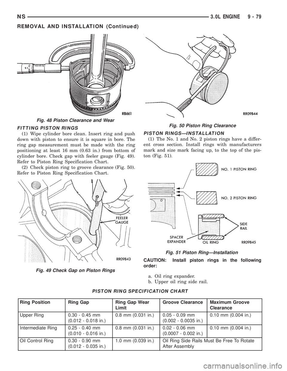
(1) Wipe cylinder bore clean. Insert ring and push
down with piston to ensure it is square in bore. The
ring gap measurement must be made with the ring
positioning at least 16 mm (0.63 in.) from bottom of
cylinder bore. Check gap with feeler gauge (Fig. 49).
Refer to Piston Ring Specification Chart.
(2) Check piston ring to groove clearance (Fig. 50).
Refer to Piston Ring Specification Chart.PISTON RINGSÐINSTALLATION
(1) The No. 1 and No. 2 piston rings have a differ-
ent cross section. Install rings with manufacturers
mark and size mark facing up, to the top of the pis-
ton (Fig. 51).
CAUTION: Install piston rings in the following
order:
a. Oil ring expander.
b. Upper oil ring side rail.
PISTON RING SPECIFICATION CHART
Ring Position Ring Gap Ring Gap Wear
LimitGroove Clearance Maximum Groove
Clearance
Upper Ring 0.30 - 0.45 mm
(0.012 - 0.018 in.)0.8 mm (0.031 in.) 0.05 - 0.09 mm
(0.002 - 0.0035 in.)0.10 mm (0.004 in.)
Intermediate Ring 0.25 - 0.40 mm
(0.010 - 0.016 in.)0.8 mm (0.031 in.) 0.02 - 0.06 mm
(0.0007 - 0.002 in.)0.10 mm (0.004 in.)
Oil Control Ring 0.30 - 0.90 mm
(0.012 - 0.035 in.)1.0 mm (0.039 in.) Oil Ring Side Rails Must Be Free To Rotate
After Assembly
Fig. 48 Piston Clearance and Wear
Fig. 49 Check Gap on Piston Rings
Fig. 50 Piston Ring Clearance
Fig. 51 Piston RingÐInstallation
NS3.0L ENGINE 9 - 79
REMOVAL AND INSTALLATION (Continued)
Page 1130 of 1938

c. Lower oil ring side rail.
d. No. 2 Intermediate piston ring.
e. No. 1 Upper piston ring.
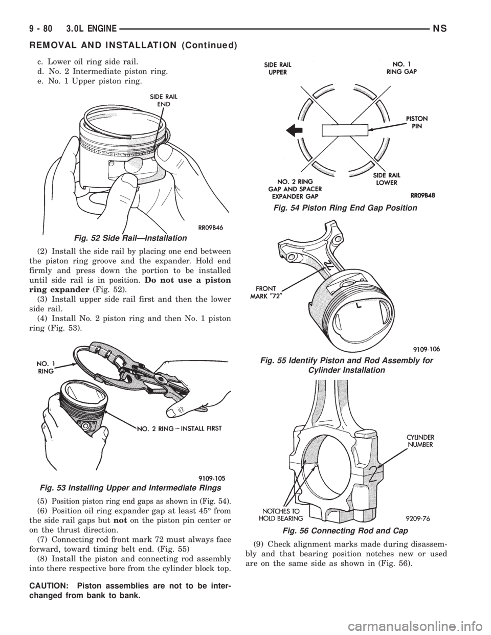
(2) Install the side rail by placing one end between
the piston ring groove and the expander. Hold end
firmly and press down the portion to be installed
until side rail is in position.Do not use a piston
ring expander(Fig. 52).
(3) Install upper side rail first and then the lower
side rail.
(4) Install No. 2 piston ring and then No. 1 piston
ring (Fig. 53).
(5)
Position piston ring end gaps as shown in (Fig. 54).
(6) Position oil ring expander gap at least 45É from
the side rail gaps butnoton the piston pin center or
on the thrust direction.
(7) Connecting rod front mark 72 must always face
forward, toward timing belt end. (Fig. 55)
(8) Install the piston and connecting rod assembly
into there respective bore from the cylinder block top.
CAUTION: Piston assemblies are not to be inter-
changed from bank to bank.(9) Check alignment marks made during disassem-
bly and that bearing position notches new or used
are on the same side as shown in (Fig. 56).
Fig. 52 Side RailÐInstallation
Fig. 53 Installing Upper and Intermediate Rings
Fig. 54 Piston Ring End Gap Position
Fig. 55 Identify Piston and Rod Assembly for
Cylinder Installation
Fig. 56 Connecting Rod and Cap
9 - 80 3.0L ENGINENS
REMOVAL AND INSTALLATION (Continued)
Page 1131 of 1938
CRANKSHAFT
REMOVAL
(1) Remove front mounted oil pump assembly and
gasket (Fig. 57) and (Fig. 58).
(2) Remove rear oil seal retainer and seal as
assembly (Fig. 59).(3) Release mono-block main bearing cap bolts
evenly. Remove lower bearing shells and identify for
reassembly.
(4) Lift out crankshaft and remove upper thrust
washers from each side of number three main bear-
ing in the crankcase (Fig. 57).
Fig. 57 Crankshaft and Cylinder Block
Fig. 58 Oil Pump Assembly
Fig. 59 Rear Seal Assembly
NS3.0L ENGINE 9 - 81
REMOVAL AND INSTALLATION (Continued)