1996 CHRYSLER VOYAGER engine
[x] Cancel search: enginePage 1148 of 1938
with an old bearing half. Do not file the rods or
bearing caps.
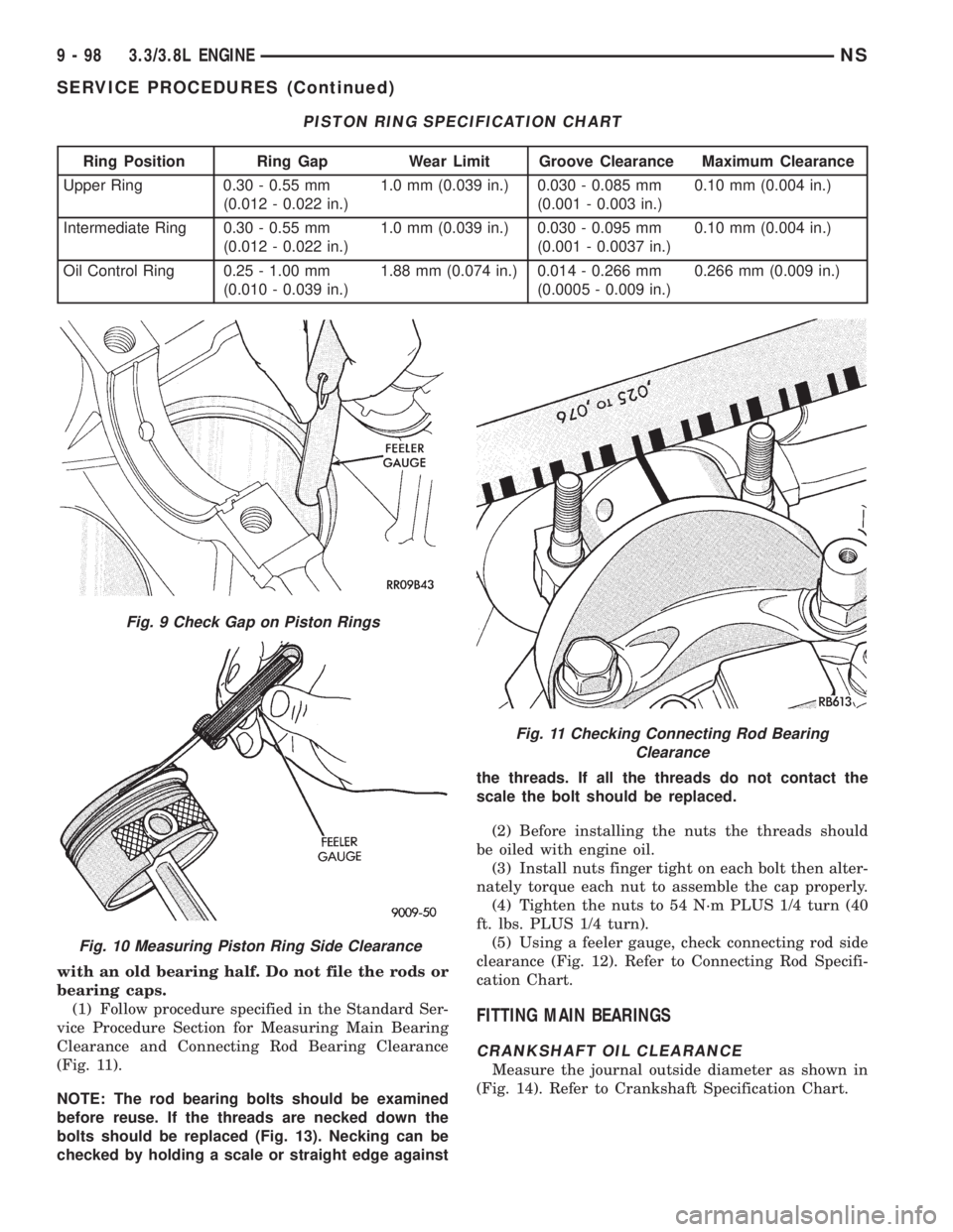
(1) Follow procedure specified in the Standard Ser-
vice Procedure Section for Measuring Main Bearing
Clearance and Connecting Rod Bearing Clearance
(Fig. 11).
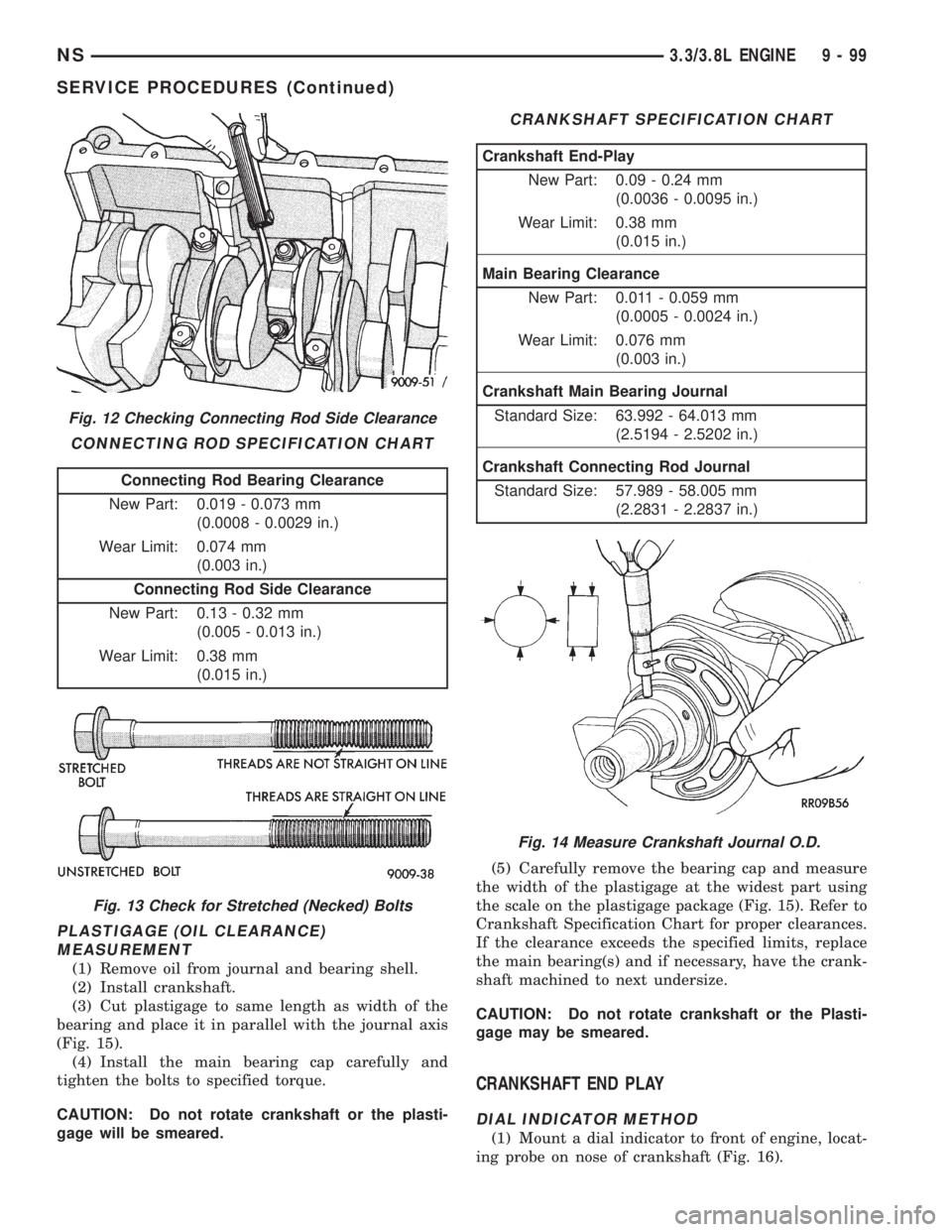
NOTE: The rod bearing bolts should be examined
before reuse. If the threads are necked down the
bolts should be replaced (Fig. 13). Necking can be
checked by holding a scale or straight edge againstthe threads. If all the threads do not contact the
scale the bolt should be replaced.
(2) Before installing the nuts the threads should
be oiled with engine oil.
(3) Install nuts finger tight on each bolt then alter-
nately torque each nut to assemble the cap properly.
(4) Tighten the nuts to 54 N´m PLUS 1/4 turn (40
ft. lbs. PLUS 1/4 turn).
(5) Using a feeler gauge, check connecting rod side
clearance (Fig. 12). Refer to Connecting Rod Specifi-
cation Chart.
FITTING MAIN BEARINGS
CRANKSHAFT OIL CLEARANCE
Measure the journal outside diameter as shown in
(Fig. 14). Refer to Crankshaft Specification Chart.
PISTON RING SPECIFICATION CHART
Ring Position Ring Gap Wear Limit Groove Clearance Maximum Clearance
Upper Ring 0.30 - 0.55 mm
(0.012 - 0.022 in.)1.0 mm (0.039 in.) 0.030 - 0.085 mm
(0.001 - 0.003 in.)0.10 mm (0.004 in.)
Intermediate Ring 0.30 - 0.55 mm
(0.012 - 0.022 in.)1.0 mm (0.039 in.) 0.030 - 0.095 mm
(0.001 - 0.0037 in.)0.10 mm (0.004 in.)
Oil Control Ring 0.25 - 1.00 mm
(0.010 - 0.039 in.)1.88 mm (0.074 in.) 0.014 - 0.266 mm
(0.0005 - 0.009 in.)0.266 mm (0.009 in.)
Fig. 9 Check Gap on Piston Rings
Fig. 10 Measuring Piston Ring Side Clearance
Fig. 11 Checking Connecting Rod Bearing
Clearance
9 - 98 3.3/3.8L ENGINENS
SERVICE PROCEDURES (Continued)
Page 1149 of 1938
PLASTIGAGE (OIL CLEARANCE)
MEASUREMENT
(1) Remove oil from journal and bearing shell.
(2) Install crankshaft.
(3) Cut plastigage to same length as width of the
bearing and place it in parallel with the journal axis
(Fig. 15).
(4) Install the main bearing cap carefully and
tighten the bolts to specified torque.
CAUTION: Do not rotate crankshaft or the plasti-
gage will be smeared.(5) Carefully remove the bearing cap and measure
the width of the plastigage at the widest part using
the scale on the plastigage package (Fig. 15). Refer to
Crankshaft Specification Chart for proper clearances.
If the clearance exceeds the specified limits, replace
the main bearing(s) and if necessary, have the crank-
shaft machined to next undersize.
CAUTION: Do not rotate crankshaft or the Plasti-
gage may be smeared.
CRANKSHAFT END PLAY
DIAL INDICATOR METHOD
(1) Mount a dial indicator to front of engine, locat-
ing probe on nose of crankshaft (Fig. 16).
Fig. 12 Checking Connecting Rod Side Clearance
CONNECTING ROD SPECIFICATION CHART
Connecting Rod Bearing Clearance
New Part: 0.019 - 0.073 mm
(0.0008 - 0.0029 in.)
Wear Limit: 0.074 mm
(0.003 in.)
Connecting Rod Side Clearance
New Part: 0.13 - 0.32 mm
(0.005 - 0.013 in.)
Wear Limit: 0.38 mm
(0.015 in.)
Fig. 13 Check for Stretched (Necked) Bolts
CRANKSHAFT SPECIFICATION CHART
Crankshaft End-Play
New Part: 0.09 - 0.24 mm
(0.0036 - 0.0095 in.)
Wear Limit: 0.38 mm
(0.015 in.)
Main Bearing Clearance
New Part: 0.011 - 0.059 mm
(0.0005 - 0.0024 in.)
Wear Limit: 0.076 mm
(0.003 in.)
Crankshaft Main Bearing Journal
Standard Size: 63.992 - 64.013 mm
(2.5194 - 2.5202 in.)
Crankshaft Connecting Rod Journal
Standard Size: 57.989 - 58.005 mm
(2.2831 - 2.2837 in.)
Fig. 14 Measure Crankshaft Journal O.D.
NS3.3/3.8L ENGINE 9 - 99
SERVICE PROCEDURES (Continued)
Page 1150 of 1938
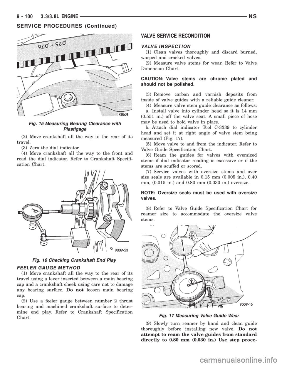
(2) Move crankshaft all the way to the rear of its
travel.
(3) Zero the dial indicator.
(4) Move crankshaft all the way to the front and
read the dial indicator. Refer to Crankshaft Specifi-
cation Chart.
FEELER GAUGE METHOD
(1) Move crankshaft all the way to the rear of its
travel using a lever inserted between a main bearing
cap and a crankshaft cheek using care not to damage
any bearing surface.Do notloosen main bearing
cap.
(2) Use a feeler gauge between number 2 thrust
bearing and machined crankshaft surface to deter-
mine end play. Refer to Crankshaft Specification
Chart.
VALVE SERVICE RECONDITION
VALVE INSPECTION
(1) Clean valves thoroughly and discard burned,
warped and cracked valves.
(2) Measure valve stems for wear. Refer to Valve
Dimension Chart.
CAUTION: Valve stems are chrome plated and
should not be polished.
(3) Remove carbon and varnish deposits from
inside of valve guides with a reliable guide cleaner.
(4) Measure valve stem guide clearance as follows:
a. Install valve into cylinder head so it is 14 mm
(0.551 in.) off the valve seat. A small piece of hose
may be used to hold valve in place.
b. Attach dial indicator Tool C-3339 to cylinder
head and set it at right angle of valve stem being
measured (Fig. 17).
(5) Move valve to and from the indicator. Refer to
Valve Guide Specification Chart.
(6) Ream the guides for valves with oversized
stems if dial indicator reading is excessive or if the
stems are scuffed or scored.
(7) Service valves with oversize stems and over
size seals are available in 0.15 mm (0.005 in.), 0.40
mm, (0.015 in.) and 0.80 mm (0.030 in.) oversize.
NOTE: Oversize seals must be used with oversize
valves.
(8) Refer to Valve Guide Specification Chart for
reamer size to accommodate the oversize valve
stems.
(9) Slowly turn reamer by hand and clean guide
thoroughly before installing new valve.Do not
attempt to ream the valve guides from standard
directly to 0.80 mm (0.030 in.) Use step proce-
Fig. 15 Measuring Bearing Clearance with
Plastigage
Fig. 16 Checking Crankshaft End Play
Fig. 17 Measuring Valve Guide Wear
9 - 100 3.3/3.8L ENGINENS
SERVICE PROCEDURES (Continued)
Page 1151 of 1938
dure of 0.15 mm (0.005 in.), 0.40 mm (0.015 in.)
and 0.80 mm (0.030 in.) so the valve guides may
be reamed true in relation to the valve seat.
After reaming guides, the seat runout should be
measured and resurfaced if necessary. See
Refacing Valves and Valve Seats.VALVE GUIDES
NOTE: Replace cylinder head if guide does not
clean up with 0.80 mm (0.030 in.) oversize reamer,
or if guide is loose in cylinder head.
REFACING VALVES AND VALVE SEATS
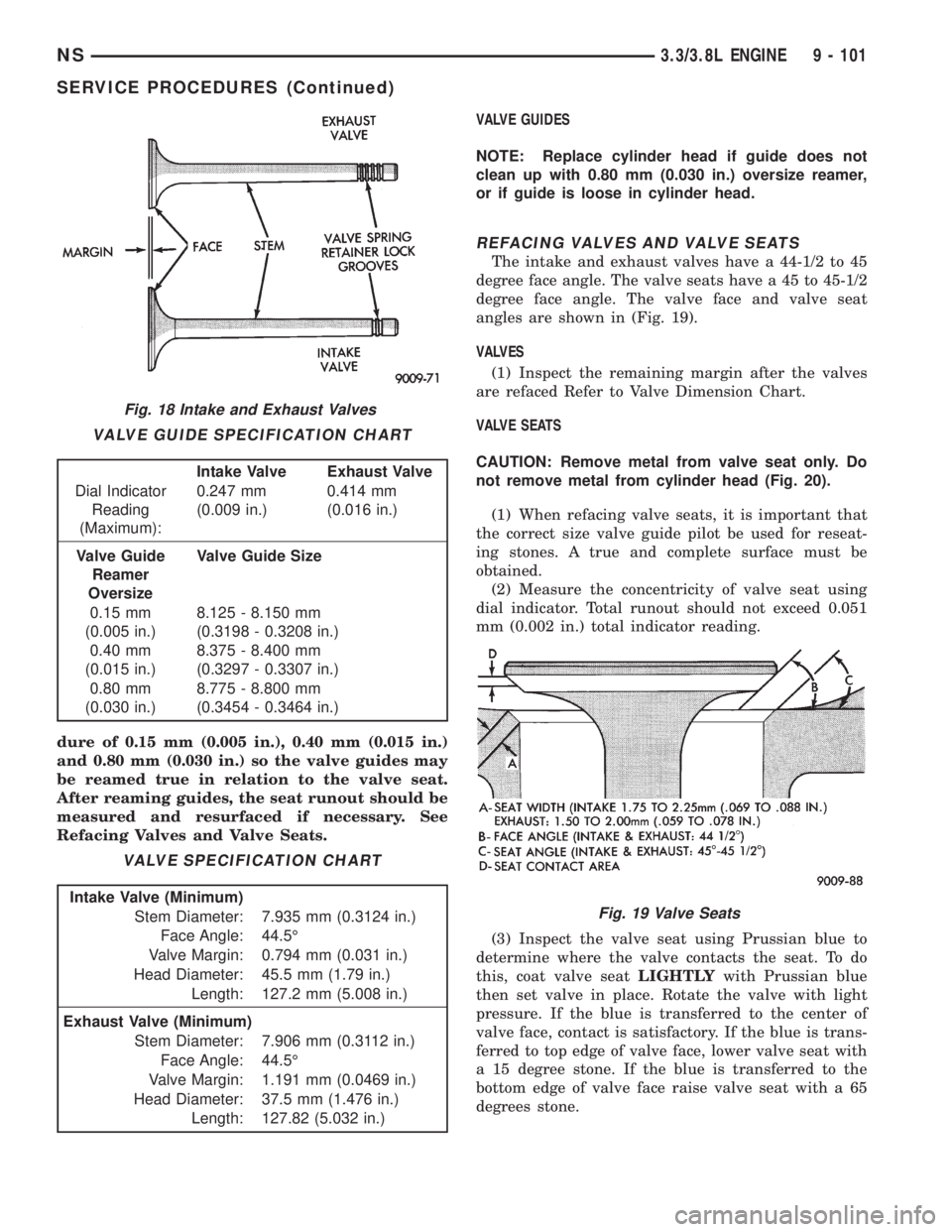
The intake and exhaust valves have a 44-1/2 to 45
degree face angle. The valve seats have a 45 to 45-1/2
degree face angle. The valve face and valve seat
angles are shown in (Fig. 19).
VALVES
(1) Inspect the remaining margin after the valves
are refaced Refer to Valve Dimension Chart.
VALVE SEATS
CAUTION: Remove metal from valve seat only. Do
not remove metal from cylinder head (Fig. 20).
(1) When refacing valve seats, it is important that
the correct size valve guide pilot be used for reseat-
ing stones. A true and complete surface must be
obtained.
(2) Measure the concentricity of valve seat using
dial indicator. Total runout should not exceed 0.051
mm (0.002 in.) total indicator reading.
(3) Inspect the valve seat using Prussian blue to
determine where the valve contacts the seat. To do
this, coat valve seatLIGHTLYwith Prussian blue
then set valve in place. Rotate the valve with light
pressure. If the blue is transferred to the center of
valve face, contact is satisfactory. If the blue is trans-
ferred to top edge of valve face, lower valve seat with
a 15 degree stone. If the blue is transferred to the
bottom edge of valve face raise valve seat with a 65
degrees stone.
Fig. 18 Intake and Exhaust Valves
VALVE GUIDE SPECIFICATION CHART
Intake Valve Exhaust Valve
Dial Indicator
Reading
(Maximum):0.247 mm
(0.009 in.)0.414 mm
(0.016 in.)
Valve Guide
Reamer
OversizeValve Guide Size
0.15 mm
(0.005 in.)8.125 - 8.150 mm
(0.3198 - 0.3208 in.)
0.40 mm
(0.015 in.)8.375 - 8.400 mm
(0.3297 - 0.3307 in.)
0.80 mm
(0.030 in.)8.775 - 8.800 mm
(0.3454 - 0.3464 in.)
VALVE SPECIFICATION CHART
Intake Valve (Minimum)
Stem Diameter: 7.935 mm (0.3124 in.)
Face Angle: 44.5É
Valve Margin: 0.794 mm (0.031 in.)
Head Diameter: 45.5 mm (1.79 in.)
Length: 127.2 mm (5.008 in.)
Exhaust Valve (Minimum)
Stem Diameter: 7.906 mm (0.3112 in.)
Face Angle: 44.5É
Valve Margin: 1.191 mm (0.0469 in.)
Head Diameter: 37.5 mm (1.476 in.)
Length: 127.82 (5.032 in.)
Fig. 19 Valve Seats
NS3.3/3.8L ENGINE 9 - 101
SERVICE PROCEDURES (Continued)
Page 1152 of 1938
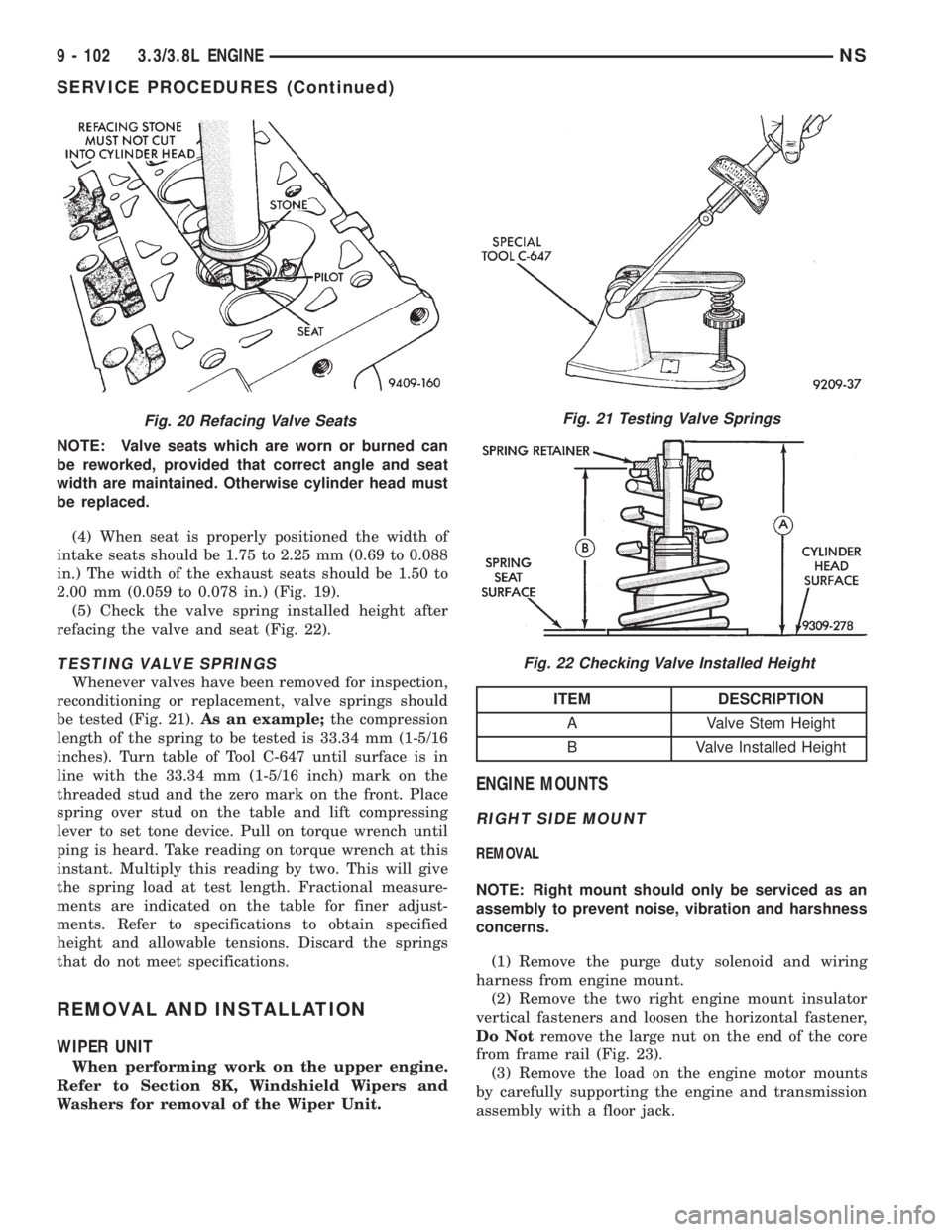
NOTE: Valve seats which are worn or burned can
be reworked, provided that correct angle and seat
width are maintained. Otherwise cylinder head must
be replaced.
(4) When seat is properly positioned the width of
intake seats should be 1.75 to 2.25 mm (0.69 to 0.088
in.) The width of the exhaust seats should be 1.50 to
2.00 mm (0.059 to 0.078 in.) (Fig. 19).
(5) Check the valve spring installed height after
refacing the valve and seat (Fig. 22).
TESTING VALVE SPRINGS
Whenever valves have been removed for inspection,
reconditioning or replacement, valve springs should
be tested (Fig. 21).As an example;the compression
length of the spring to be tested is 33.34 mm (1-5/16
inches). Turn table of Tool C-647 until surface is in
line with the 33.34 mm (1-5/16 inch) mark on the
threaded stud and the zero mark on the front. Place
spring over stud on the table and lift compressing
lever to set tone device. Pull on torque wrench until
ping is heard. Take reading on torque wrench at this
instant. Multiply this reading by two. This will give
the spring load at test length. Fractional measure-
ments are indicated on the table for finer adjust-
ments. Refer to specifications to obtain specified
height and allowable tensions. Discard the springs
that do not meet specifications.
REMOVAL AND INSTALLATION
WIPER UNIT
When performing work on the upper engine.
Refer to Section 8K, Windshield Wipers and
Washers for removal of the Wiper Unit.
ENGINE MOUNTS
RIGHT SIDE MOUNT
REMOVAL
NOTE: Right mount should only be serviced as an
assembly to prevent noise, vibration and harshness
concerns.
(1) Remove the purge duty solenoid and wiring
harness from engine mount.
(2) Remove the two right engine mount insulator
vertical fasteners and loosen the horizontal fastener,
Do Notremove the large nut on the end of the core
from frame rail (Fig. 23).
(3) Remove the load on the engine motor mounts
by carefully supporting the engine and transmission
assembly with a floor jack.
Fig. 20 Refacing Valve SeatsFig. 21 Testing Valve Springs
Fig. 22 Checking Valve Installed Height
ITEM DESCRIPTION
A Valve Stem Height
B Valve Installed Height
9 - 102 3.3/3.8L ENGINENS
SERVICE PROCEDURES (Continued)
Page 1153 of 1938
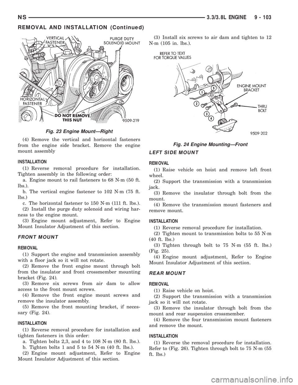
(4) Remove the vertical and horizontal fasteners
from the engine side bracket. Remove the engine
mount assembly
INSTALLATION
(1) Reverse removal procedure for installation.
Tighten assembly in the following order:
a. Engine mount to rail fasteners to 68 N´m (50 ft.
lbs.).
b. The vertical engine fastener to 102 N´m (75 ft.
lbs.)
c. The horizontal fastener to 150 N´m (111 ft. lbs.).
(2) Install the purge duty solenoid and wiring har-
ness to the engine mount.
(3) Engine mount adjustment, Refer to Engine
Mount Insulator Adjustment of this section.
FRONT MOUNT
REMOVAL
(1) Support the engine and transmission assembly
with a floor jack so it will not rotate.
(2) Remove the front engine mount through bolt
from the insulator and front crossmember mounting
bracket (Fig. 24).
(3) Remove six screws from air dam to allow
access to the front mount screws.
(4) Remove the front engine mount screws and
remove the insulator assembly.
(5) Remove the front mounting bracket, if neces-
sary (Fig. 24).
INSTALLATION
(1) Reverse removal procedure for installation and
tighten fasteners in this order:
a. Tighten bolts 2,3, and 4 to 108 N´m (80 ft. lbs.).
b. Tighten bolts 1 and 5 to 54 N´m (40 ft. lbs.).
(2) Engine mount adjustment, Refer to Engine
Mount Insulator Adjustment of this section.(3) Install six screws to air dam and tighten to 12
N´m (105 in. lbs.).
LEFT SIDE MOUNT
REMOVAL
(1) Raise vehicle on hoist and remove left front
wheel.
(2) Support the transmission with a transmission
jack.
(3) Remove the insulator through bolt from the
mount.
(4) Remove the transmission mount fasteners and
remove mount.
INSTALLATION
(1) Reverse removal procedure for installation.
(2) Tighten mount to transmission bolts to 55 N´m
(40 ft. lbs.)
(3) Tighten through bolt to 75 N´m (55 ft. lbs.)
(Fig. 25).
(4) Engine mount adjustment, Refer to Engine
Mount Insulator Adjustment of this section.
REAR MOUNT
REMOVAL
(1) Raise vehicle on hoist.
(2) Support the transmission with a transmission
jack so it will not rotate.
(3) Remove the insulator through bolt from the
mount and rear suspension crossmember.
(4) Remove the four transmission mount fasteners
and remove the mount.
INSTALLATION
(1) Reverse the removal procedure for installation.
Refer to (Fig. 26). Tighten through bolt to 75 N´m (55
ft. lbs.)
Fig. 23 Engine MountÐRight
Fig. 24 Engine MountingÐFront
NS3.3/3.8L ENGINE 9 - 103
REMOVAL AND INSTALLATION (Continued)
Page 1154 of 1938
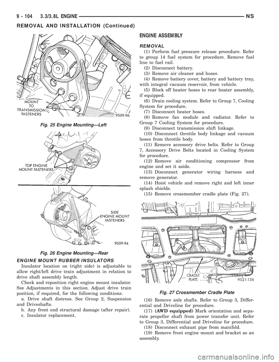
ENGINE MOUNT RUBBER INSULATORS
Insulator location on (right side) is adjustable to
allow right/left drive train adjustment in relation to
drive shaft assembly length.
Check and reposition right engine mount insulator.
See Adjustments in this section. Adjust drive train
position, if required, for the following conditions:
a. Drive shaft distress. See Group 2, Suspension
and Driveshafts.
b. Any front end structural damage (after repair).
c. Insulator replacement.
ENGINE ASSEMBLY
REMOVAL
(1) Perform fuel pressure release procedure. Refer
to group 14 fuel system for procedure. Remove fuel
line to fuel rail.
(2) Disconnect battery.
(3) Remove air cleaner and hoses.
(4) Remove battery cover, battery and battery tray,
with integral vacuum reservoir, from vehicle.
(5) Block off heater hoses to rear heater assembly,
if equipped.
(6) Drain cooling system. Refer to Group 7, Cooling
System for procedure.
(7) Disconnect heater hoses.
(8) Remove fan module and radiator. Refer to
Group 7 Cooling System for procedure.
(9) Disconnect transmission shift linkage.
(10) Disconnect throttle body linkage and vacuum
hoses from throttle body.
(11) Remove accessory drive belts. Refer to Group
7, Accessory Drive Belts located in Cooling System
for procedure.
(12) Remove air conditioning compressor from
engine and set it aside.
(13) Disconnect generator wiring harness and
remove generator.
(14) Hoist vehicle and remove right and left inner
splash shields.
(15) Remove crossmember cradle plate (Fig. 27).
(16) Remove axle shafts. Refer to Group 3, Differ-
ential and Driveline for procedure.
(17)(AWD equipped)Mark orientation and sepa-
rate propeller shaft from power transfer unit. Refer
to Group 3, Differential and Driveline for procedure.
(18) Disconnect exhaust pipe from manifold.
(19) Remove front engine mount and bracket as an
assembly.
Fig. 25 Engine MountingÐLeft
Fig. 26 Engine MountingÐRear
Fig. 27 Crossmember Cradle Plate
9 - 104 3.3/3.8L ENGINENS
REMOVAL AND INSTALLATION (Continued)
Page 1155 of 1938
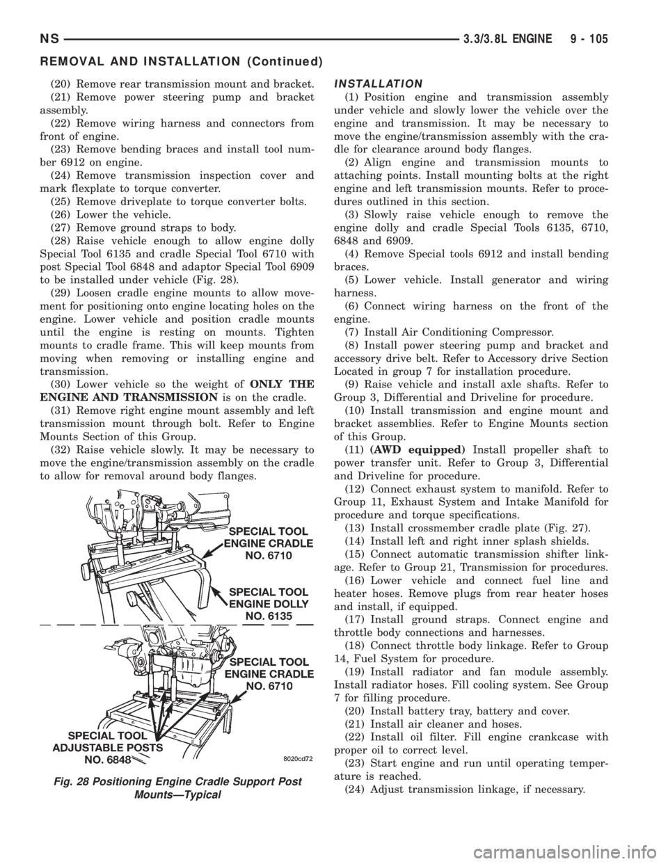
(20) Remove rear transmission mount and bracket.
(21) Remove power steering pump and bracket
assembly.
(22) Remove wiring harness and connectors from
front of engine.
(23) Remove bending braces and install tool num-
ber 6912 on engine.
(24) Remove transmission inspection cover and
mark flexplate to torque converter.
(25) Remove driveplate to torque converter bolts.
(26) Lower the vehicle.
(27) Remove ground straps to body.
(28) Raise vehicle enough to allow engine dolly
Special Tool 6135 and cradle Special Tool 6710 with
post Special Tool 6848 and adaptor Special Tool 6909
to be installed under vehicle (Fig. 28).
(29) Loosen cradle engine mounts to allow move-
ment for positioning onto engine locating holes on the
engine. Lower vehicle and position cradle mounts
until the engine is resting on mounts. Tighten
mounts to cradle frame. This will keep mounts from
moving when removing or installing engine and
transmission.
(30) Lower vehicle so the weight ofONLY THE
ENGINE AND TRANSMISSIONis on the cradle.
(31) Remove right engine mount assembly and left
transmission mount through bolt. Refer to Engine
Mounts Section of this Group.
(32) Raise vehicle slowly. It may be necessary to
move the engine/transmission assembly on the cradle
to allow for removal around body flanges.INSTALLATION
(1) Position engine and transmission assembly
under vehicle and slowly lower the vehicle over the
engine and transmission. It may be necessary to
move the engine/transmission assembly with the cra-
dle for clearance around body flanges.
(2) Align engine and transmission mounts to
attaching points. Install mounting bolts at the right
engine and left transmission mounts. Refer to proce-
dures outlined in this section.
(3) Slowly raise vehicle enough to remove the
engine dolly and cradle Special Tools 6135, 6710,
6848 and 6909.
(4) Remove Special tools 6912 and install bending
braces.
(5) Lower vehicle. Install generator and wiring
harness.
(6) Connect wiring harness on the front of the
engine.
(7) Install Air Conditioning Compressor.
(8) Install power steering pump and bracket and
accessory drive belt. Refer to Accessory drive Section
Located in group 7 for installation procedure.
(9) Raise vehicle and install axle shafts. Refer to
Group 3, Differential and Driveline for procedure.
(10) Install transmission and engine mount and
bracket assemblies. Refer to Engine Mounts section
of this Group.
(11)(AWD equipped)Install propeller shaft to
power transfer unit. Refer to Group 3, Differential
and Driveline for procedure.
(12) Connect exhaust system to manifold. Refer to
Group 11, Exhaust System and Intake Manifold for
procedure and torque specifications.
(13) Install crossmember cradle plate (Fig. 27).
(14) Install left and right inner splash shields.
(15) Connect automatic transmission shifter link-
age. Refer to Group 21, Transmission for procedures.
(16) Lower vehicle and connect fuel line and
heater hoses. Remove plugs from rear heater hoses
and install, if equipped.
(17) Install ground straps. Connect engine and
throttle body connections and harnesses.
(18) Connect throttle body linkage. Refer to Group
14, Fuel System for procedure.
(19) Install radiator and fan module assembly.
Install radiator hoses. Fill cooling system. See Group
7 for filling procedure.
(20) Install battery tray, battery and cover.
(21) Install air cleaner and hoses.
(22) Install oil filter. Fill engine crankcase with
proper oil to correct level.
(23) Start engine and run until operating temper-
ature is reached.
(24) Adjust transmission linkage, if necessary.
Fig. 28 Positioning Engine Cradle Support Post
MountsÐTypical
NS3.3/3.8L ENGINE 9 - 105
REMOVAL AND INSTALLATION (Continued)