1996 CHRYSLER VOYAGER engine
[x] Cancel search: enginePage 1164 of 1938
0.310 mm (0.012 in. Max.). If not within limits install
a new thrust plate.
(10) Each tappet reused must be installed in the
same position from which it was removed.When
camshaft is replaced, all of the tappets must be
replaced.
CAMSHAFT BEARINGS
REMOVAL
(1) With engine removed from vehicle and com-
pletely disassembled, drive out rear cam bearing core
hole plug.
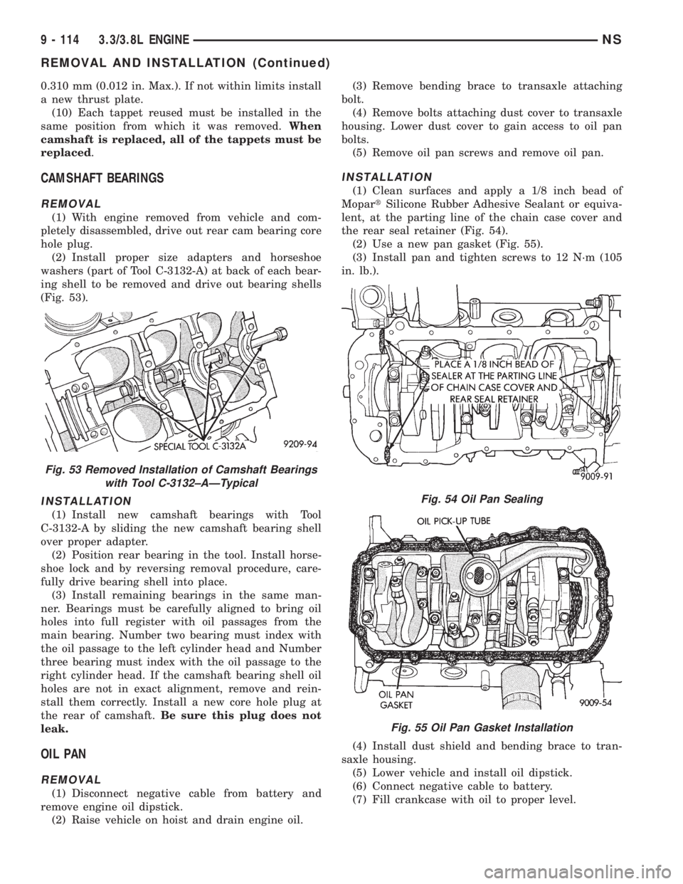
(2) Install proper size adapters and horseshoe
washers (part of Tool C-3132-A) at back of each bear-
ing shell to be removed and drive out bearing shells
(Fig. 53).
INSTALLATION
(1) Install new camshaft bearings with Tool
C-3132-A by sliding the new camshaft bearing shell
over proper adapter.
(2) Position rear bearing in the tool. Install horse-
shoe lock and by reversing removal procedure, care-
fully drive bearing shell into place.
(3) Install remaining bearings in the same man-
ner. Bearings must be carefully aligned to bring oil
holes into full register with oil passages from the
main bearing. Number two bearing must index with
the oil passage to the left cylinder head and Number
three bearing must index with the oil passage to the
right cylinder head. If the camshaft bearing shell oil
holes are not in exact alignment, remove and rein-
stall them correctly. Install a new core hole plug at
the rear of camshaft.Be sure this plug does not
leak.
OIL PAN
REMOVAL
(1) Disconnect negative cable from battery and
remove engine oil dipstick.
(2) Raise vehicle on hoist and drain engine oil.(3) Remove bending brace to transaxle attaching
bolt.
(4) Remove bolts attaching dust cover to transaxle
housing. Lower dust cover to gain access to oil pan
bolts.
(5) Remove oil pan screws and remove oil pan.
INSTALLATION
(1) Clean surfaces and apply a 1/8 inch bead of
MopartSilicone Rubber Adhesive Sealant or equiva-
lent, at the parting line of the chain case cover and
the rear seal retainer (Fig. 54).
(2) Use a new pan gasket (Fig. 55).
(3) Install pan and tighten screws to 12 N´m (105
in. lb.).
(4) Install dust shield and bending brace to tran-
saxle housing.
(5) Lower vehicle and install oil dipstick.
(6) Connect negative cable to battery.
(7) Fill crankcase with oil to proper level.
Fig. 53 Removed Installation of Camshaft Bearings
with Tool C-3132±AÐTypical
Fig. 54 Oil Pan Sealing
Fig. 55 Oil Pan Gasket Installation
9 - 114 3.3/3.8L ENGINENS
REMOVAL AND INSTALLATION (Continued)
Page 1165 of 1938
PISTON AND CONNECTING ROD
REMOVAL
(1) Disconnect negative cable from battery.
(2) Remove cylinder heads and oil pan. Refer to
procedure outlined in this section.
(3) Remove top ridge of cylinder bores with a reli-
able ridge reamer before removing pistons from cyl-
inder block.Be sure to keep tops of pistons
covered during this operation. Pistons and con-
necting rods must be removed from top of cyl-
inder block. When removing piston and
connecting rod assemblies from the engine,
rotate crankshaft so that each connecting rod
is centered in cylinder bore.
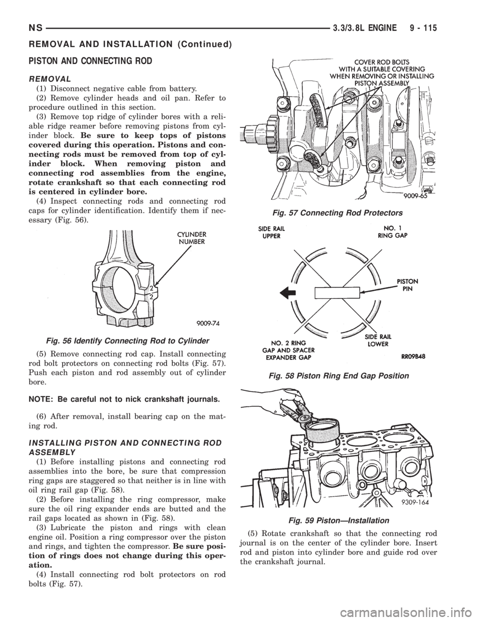
(4) Inspect connecting rods and connecting rod
caps for cylinder identification. Identify them if nec-
essary (Fig. 56).
(5) Remove connecting rod cap. Install connecting
rod bolt protectors on connecting rod bolts (Fig. 57).
Push each piston and rod assembly out of cylinder
bore.
NOTE: Be careful not to nick crankshaft journals.
(6) After removal, install bearing cap on the mat-
ing rod.
INSTALLING PISTON AND CONNECTING ROD
ASSEMBLY
(1) Before installing pistons and connecting rod
assemblies into the bore, be sure that compression
ring gaps are staggered so that neither is in line with
oil ring rail gap (Fig. 58).
(2) Before installing the ring compressor, make
sure the oil ring expander ends are butted and the
rail gaps located as shown in (Fig. 58).
(3) Lubricate the piston and rings with clean
engine oil. Position a ring compressor over the piston
and rings, and tighten the compressor.Be sure posi-
tion of rings does not change during this oper-
ation.
(4) Install connecting rod bolt protectors on rod
bolts (Fig. 57).(5) Rotate crankshaft so that the connecting rod
journal is on the center of the cylinder bore. Insert
rod and piston into cylinder bore and guide rod over
the crankshaft journal.
Fig. 56 Identify Connecting Rod to Cylinder
Fig. 57 Connecting Rod Protectors
Fig. 58 Piston Ring End Gap Position
Fig. 59 PistonÐInstallation
NS3.3/3.8L ENGINE 9 - 115
REMOVAL AND INSTALLATION (Continued)
Page 1166 of 1938
(6) Tap the piston down in cylinder bore, using a
hammer handle. At the same time, guide connecting
rod into position on connecting rod journal.
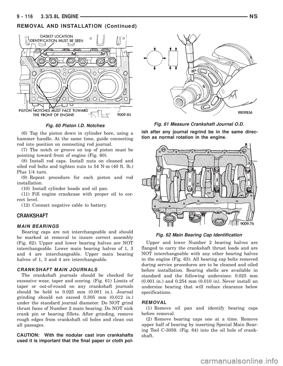
(7) The notch or groove on top of piston must be
pointing toward front of engine (Fig. 60).
(8) Install rod caps. Install nuts on cleaned and
oiled rod bolts and tighten nuts to 54 N´m (40 ft. lb.)
Plus 1/4 turn.
(9) Repeat procedure for each piston and rod
installation.
(10) Install cylinder heads and oil pan.
(11) Fill engine crankcase with proper oil to cor-
rect level.
(12) Connect negative cable to battery.
CRANKSHAFT
MAIN BEARINGS
Bearing caps are not interchangeable and should
be marked at removal to insure correct assembly
(Fig. 62). Upper and lower bearing halves are NOT
interchangeable. Lower main bearing halves of 1, 3
and 4 are interchangeable. Upper main bearing
halves of 1, 3 and 4 are interchangeable.
CRANKSHAFT MAIN JOURNALS
The crankshaft journals should be checked for
excessive wear, taper and scoring. (Fig. 61) Limits of
taper or out-of-round on any crankshaft journals
should be held to 0.025 mm (0.001 in.). Journal
grinding should not exceed 0.305 mm (0.012 in.)
under the standard journal diameter. Do NOT grind
thrust faces of Number 2 main bearing. Do NOT nick
crank pin or bearing fillets. After grinding, remove
rough edges from crankshaft oil holes and clean out
all passages.
CAUTION: With the nodular cast iron crankshafts
used it is important that the final paper or cloth pol-ish after any journal regrind be in the same direc-
tion as normal rotation in the engine.
Upper and lower Number 2 bearing halves are
flanged to carry the crankshaft thrust loads and are
NOT interchangeable with any other bearing halves
in the engine (Fig. 63). All bearing cap bolts removed
during service procedures are to be cleaned and oiled
before installation. Bearing shells are available in
standard and the following undersizes: 0.025 mm
(0.001 in.) and 0.254 mm (0.010 in). Never install an
undersize bearing that will reduce clearance below
specifications.
REMOVAL
(1) Remove oil pan and identify bearing caps
before removal.
(2) Remove bearing caps one at a time. Remove
upper half of bearing by inserting Special Main Bear-
ing Tool C-3059. (Fig. 64) into the oil hole of crank-
shaft.
Fig. 60 Piston I.D. NotchesFig. 61 Measure Crankshaft Journal O.D.
Fig. 62 Main Bearing Cap Identification
9 - 116 3.3/3.8L ENGINENS
REMOVAL AND INSTALLATION (Continued)
Page 1167 of 1938
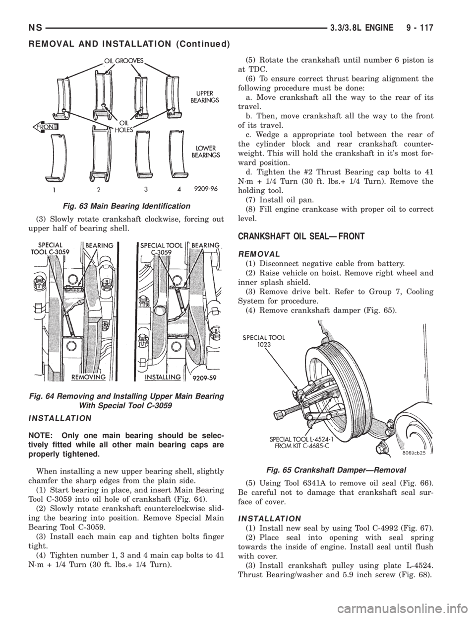
(3) Slowly rotate crankshaft clockwise, forcing out
upper half of bearing shell.
INSTALLATION
NOTE: Only one main bearing should be selec-
tively fitted while all other main bearing caps are
properly tightened.
When installing a new upper bearing shell, slightly
chamfer the sharp edges from the plain side.
(1) Start bearing in place, and insert Main Bearing
Tool C-3059 into oil hole of crankshaft (Fig. 64).
(2) Slowly rotate crankshaft counterclockwise slid-
ing the bearing into position. Remove Special Main
Bearing Tool C-3059.
(3) Install each main cap and tighten bolts finger
tight.
(4) Tighten number 1, 3 and 4 main cap bolts to 41
N´m + 1/4 Turn (30 ft. lbs.+ 1/4 Turn).(5) Rotate the crankshaft until number 6 piston is
at TDC.
(6) To ensure correct thrust bearing alignment the
following procedure must be done:
a. Move crankshaft all the way to the rear of its
travel.
b. Then, move crankshaft all the way to the front
of its travel.
c. Wedge a appropriate tool between the rear of
the cylinder block and rear crankshaft counter-
weight. This will hold the crankshaft in it's most for-
ward position.
d. Tighten the #2 Thrust Bearing cap bolts to 41
N´m + 1/4 Turn (30 ft. lbs.+ 1/4 Turn). Remove the
holding tool.
(7) Install oil pan.
(8) Fill engine crankcase with proper oil to correct
level.
CRANKSHAFT OIL SEALÐFRONT
REMOVAL
(1) Disconnect negative cable from battery.
(2) Raise vehicle on hoist. Remove right wheel and
inner splash shield.
(3) Remove drive belt. Refer to Group 7, Cooling
System for procedure.
(4) Remove crankshaft damper (Fig. 65).
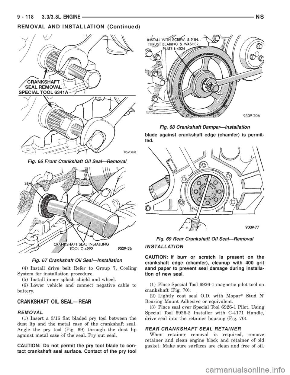
(5) Using Tool 6341A to remove oil seal (Fig. 66).
Be careful not to damage that crankshaft seal sur-
face of cover.
INSTALLATION
(1) Install new seal by using Tool C-4992 (Fig. 67).
(2) Place seal into opening with seal spring
towards the inside of engine. Install seal until flush
with cover.
(3) Install crankshaft pulley using plate L-4524.
Thrust Bearing/washer and 5.9 inch screw (Fig. 68).
Fig. 63 Main Bearing Identification
Fig. 64 Removing and Installing Upper Main Bearing
With Special Tool C-3059
Fig. 65 Crankshaft DamperÐRemoval
NS3.3/3.8L ENGINE 9 - 117
REMOVAL AND INSTALLATION (Continued)
Page 1168 of 1938
(4) Install drive belt Refer to Group 7, Cooling
System for installation procedure.
(5) Install inner splash shield and wheel.
(6) Lower vehicle and connect negative cable to
battery.
CRANKSHAFT OIL SEALÐREAR
REMOVAL
(1) Insert a 3/16 flat bladed pry tool between the
dust lip and the metal case of the crankshaft seal.
Angle the pry tool (Fig. 69) through the dust lip
against metal case of the seal. Pry out seal.
CAUTION: Do not permit the pry tool blade to con-
tact crankshaft seal surface. Contact of the pry toolblade against crankshaft edge (chamfer) is permit-
ted.
INSTALLATION
CAUTION: If burr or scratch is present on the
crankshaft edge (chamfer), cleanup with 400 grit
sand paper to prevent seal damage during installa-
tion of new seal.
(1) Place Special Tool 6926-1 magnetic pilot tool on
crankshaft (Fig. 70).
(2) Lightly coat seal O.D. with MopartStud N'
Bearing Mount Adhesive or equivalent.
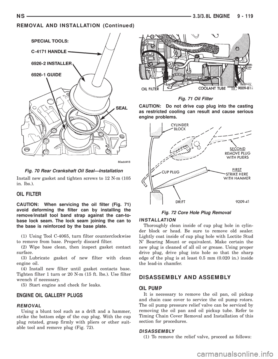
(3) Place seal over Special Tool 6926-1 Pilot. Using
Special Tool 6926-2 Installer with C-4171 Handle,
drive seal into the retainer housing (Fig. 70).
REAR CRANKSHAFT SEAL RETAINER
When retainer removal is required, remove
retainer and clean engine block and retainer of old
gasket. Make sure surfaces are clean and free of oil.
Fig. 66 Front Crankshaft Oil SealÐRemoval
Fig. 67 Crankshaft Oil SealÐInstallation
Fig. 68 Crankshaft DamperÐInstallation
Fig. 69 Rear Crankshaft Oil SealÐRemoval
9 - 118 3.3/3.8L ENGINENS
REMOVAL AND INSTALLATION (Continued)
Page 1169 of 1938
Install new gasket and tighten screws to 12 N´m (105
in. lbs.).
OIL FILTER
CAUTION: When servicing the oil filter (Fig. 71)
avoid deforming the filter can by installing the
remove/install tool band strap against the can-to-
base lock seam. The lock seam joining the can to
the base is reinforced by the base plate.
(1) Using Tool C-4065, turn filter counterclockwise
to remove from base. Properly discard filter.
(2) Wipe base clean, then inspect gasket contact
surface.
(3) Lubricate gasket of new filter with clean
engine oil.
(4) Install new filter until gasket contacts base.
Tighten filter 1 turn or 20 N´m (15 ft. lbs.). Use filter
wrench if necessary.
(5) Start engine and check for leaks.
ENGINE OIL GALLERY PLUGS
REMOVAL
Using a blunt tool such as a drift and a hammer,
strike the bottom edge of the cup plug. With the cup
plug rotated, grasp firmly with pliers or other suit-
able tool and remove plug (Fig. 72).CAUTION: Do not drive cup plug into the casting
as restricted cooling can result and cause serious
engine problems.
INSTALLATION
Thoroughly clean inside of cup plug hole in cylin-
der block or head. Be sure to remove old sealer.
Lightly coat inside of cup plug hole with Loctite Stud
N' Bearing Mount or equivalent. Make certain the
new plug is cleaned of all oil or grease. Using proper
drive plug, drive plug into hole so that the sharp
edge of the plug is at least 0.5 mm (0.020 in.) inside
the lead-in chamfer.
DISASSEMBLY AND ASSEMBLY
OIL PUMP
It is necessary to remove the oil pan, oil pickup
and chain case cover to service the oil pump rotors.
The oil pump pressure relief valve can be serviced by
removing the oil pan and oil pickup tube. Refer to
Timing Chain Cover Removal and Installation of this
section for procedures.
DISASSEMBLY
(1) To remove the relief valve, proceed as follows:
Fig. 70 Rear Crankshaft Oil SealÐInstallation
Fig. 71 Oil Filter
Fig. 72 Core Hole Plug Removal
NS3.3/3.8L ENGINE 9 - 119
REMOVAL AND INSTALLATION (Continued)
Page 1170 of 1938
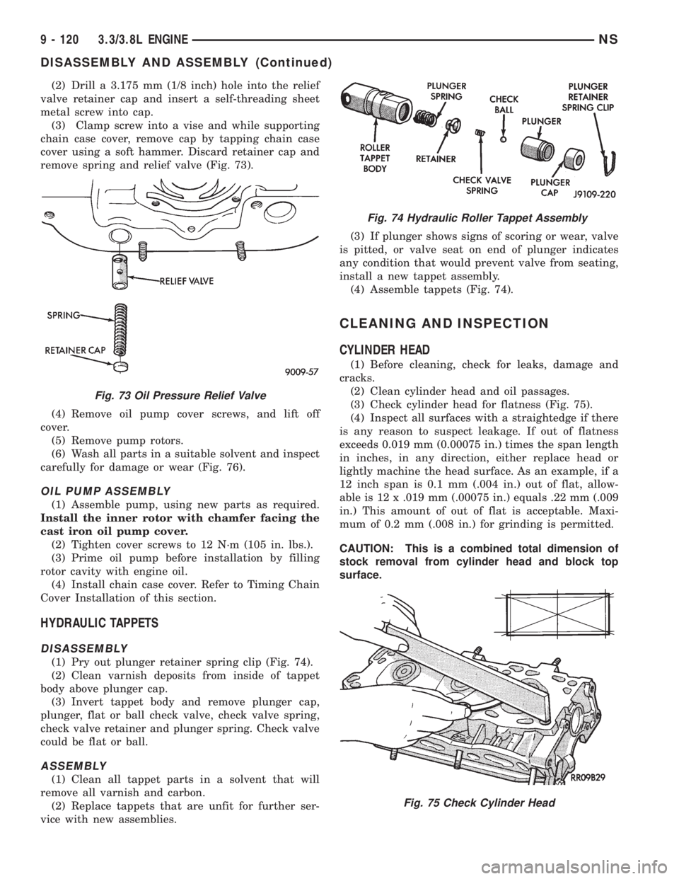
(2) Drill a 3.175 mm (1/8 inch) hole into the relief
valve retainer cap and insert a self-threading sheet
metal screw into cap.
(3) Clamp screw into a vise and while supporting
chain case cover, remove cap by tapping chain case
cover using a soft hammer. Discard retainer cap and
remove spring and relief valve (Fig. 73).
(4) Remove oil pump cover screws, and lift off
cover.
(5) Remove pump rotors.
(6) Wash all parts in a suitable solvent and inspect
carefully for damage or wear (Fig. 76).
OIL PUMP ASSEMBLY
(1) Assemble pump, using new parts as required.
Install the inner rotor with chamfer facing the
cast iron oil pump cover.
(2) Tighten cover screws to 12 N´m (105 in. lbs.).
(3) Prime oil pump before installation by filling
rotor cavity with engine oil.
(4) Install chain case cover. Refer to Timing Chain
Cover Installation of this section.
HYDRAULIC TAPPETS
DISASSEMBLY
(1) Pry out plunger retainer spring clip (Fig. 74).
(2) Clean varnish deposits from inside of tappet
body above plunger cap.
(3) Invert tappet body and remove plunger cap,
plunger, flat or ball check valve, check valve spring,
check valve retainer and plunger spring. Check valve
could be flat or ball.
ASSEMBLY
(1) Clean all tappet parts in a solvent that will
remove all varnish and carbon.
(2) Replace tappets that are unfit for further ser-
vice with new assemblies.(3) If plunger shows signs of scoring or wear, valve
is pitted, or valve seat on end of plunger indicates
any condition that would prevent valve from seating,
install a new tappet assembly.
(4) Assemble tappets (Fig. 74).
CLEANING AND INSPECTION
CYLINDER HEAD
(1) Before cleaning, check for leaks, damage and
cracks.
(2) Clean cylinder head and oil passages.
(3) Check cylinder head for flatness (Fig. 75).
(4) Inspect all surfaces with a straightedge if there
is any reason to suspect leakage. If out of flatness
exceeds 0.019 mm (0.00075 in.) times the span length
in inches, in any direction, either replace head or
lightly machine the head surface. As an example, if a
12 inch span is 0.1 mm (.004 in.) out of flat, allow-
able is 12 x .019 mm (.00075 in.) equals .22 mm (.009
in.) This amount of out of flat is acceptable. Maxi-
mum of 0.2 mm (.008 in.) for grinding is permitted.
CAUTION: This is a combined total dimension of
stock removal from cylinder head and block top
surface.
Fig. 73 Oil Pressure Relief Valve
Fig. 74 Hydraulic Roller Tappet Assembly
Fig. 75 Check Cylinder Head
9 - 120 3.3/3.8L ENGINENS
DISASSEMBLY AND ASSEMBLY (Continued)
Page 1171 of 1938
OIL PAN
(1) Clean oil pan in solvent and wipe dry with a
clean cloth. Clean all gasket material from mounting
surfaces of pan and block.
(2) Inspect oil drain plug and plug hole for
stripped or damaged threads and repair as necessary.
Install a new drain plug gasket. Tighten to 27 N´m
(20 ft. lbs.).
(3) Inspect oil pan mounting flange for bends or
distortion. Straighten flange if necessary.
(4) Clean oil screen and pipe in clean solvent.
Inspect condition of screen.
OIL PUMP
INSPECTION AND REPAIR
(1) Clean all parts thoroughly. Mating surface of
the chain case cover should be smooth. Replace pump
cover if scratched or grooved.
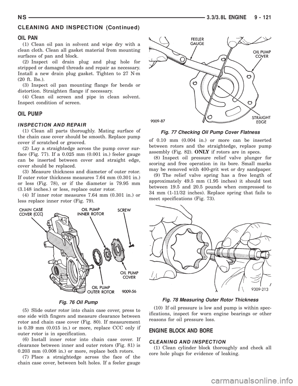
(2) Lay a straightedge across the pump cover sur-
face (Fig. 77). If a 0.025 mm (0.001 in.) feeler gauge
can be inserted between cover and straight edge,
cover should be replaced.
(3) Measure thickness and diameter of outer rotor.
If outer rotor thickness measures 7.64 mm (0.301 in.)
or less (Fig. 78), or if the diameter is 79.95 mm
(3.148 inches.) or less, replace outer rotor.
(4) If inner rotor measures 7.64 mm (0.301 in.) or
less replace inner rotor (Fig. 79).
(5) Slide outer rotor into chain case cover, press to
one side with fingers and measure clearance between
rotor and chain case cover (Fig. 80). If measurement
is 0.39 mm (0.015 in.) or more, replace CCC only if
outer rotor is in specification.
(6) Install inner rotor into chain case cover. If
clearance between inner and outer rotors (Fig. 81) is
0.203 mm (0.008 in.) or more, replace both rotors.
(7) Place a straightedge across the face of the
chain case cover, between bolt holes. If a feeler gaugeof 0.10 mm (0.004 in.) or more can be inserted
between rotors and the straightedge, replace pump
assembly (Fig. 82).ONLYif rotors are in specs.
(8) Inspect oil pressure relief valve plunger for
scoring and free operation in its bore. Small marks
may be removed with 400-grit wet or dry sandpaper.
(9) The relief valve spring has a free length of
approximately 49.5 mm (1.95 inches) it should test
between 19.5 and 20.5 pounds when compressed to
34 mm (1-11/32 inches). Replace spring that fails to
meet specifications (Fig. 73).
(10) If oil pressure is low and pump is within spec-
ifications, inspect for worn engine bearings or other
reasons for oil pressure loss.
ENGINE BLOCK AND BORE
CLEANING AND INSPECTION
(1) Clean cylinder block thoroughly and check all
core hole plugs for evidence of leaking.
Fig. 76 Oil Pump
Fig. 77 Checking Oil Pump Cover Flatness
Fig. 78 Measuring Outer Rotor Thickness
NS3.3/3.8L ENGINE 9 - 121
CLEANING AND INSPECTION (Continued)