Page 1092 of 1938
CRANKSHAFT OIL SEALÐFRONT
REMOVAL
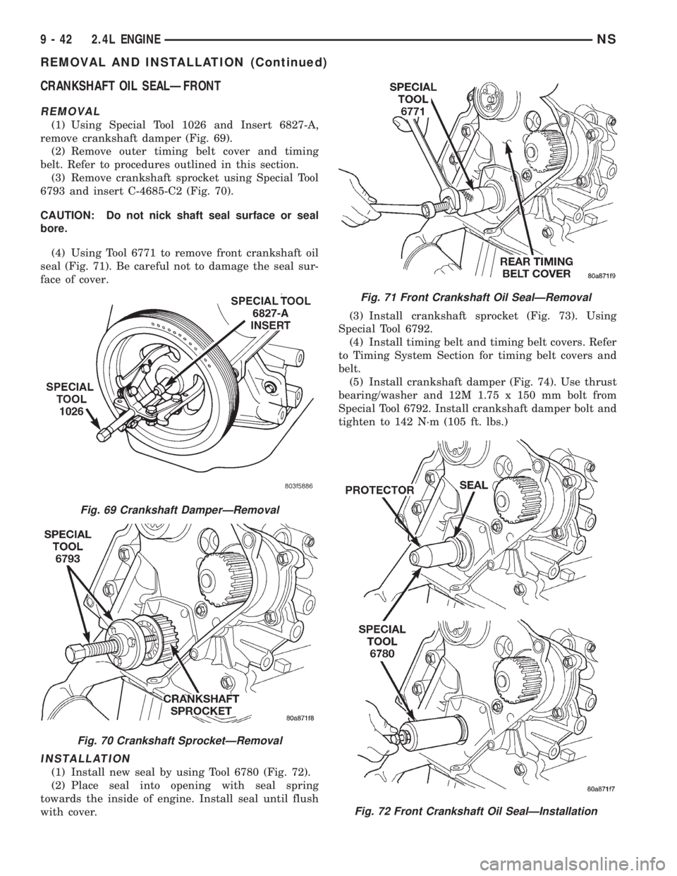
(1) Using Special Tool 1026 and Insert 6827-A,
remove crankshaft damper (Fig. 69).
(2) Remove outer timing belt cover and timing
belt. Refer to procedures outlined in this section.
(3) Remove crankshaft sprocket using Special Tool
6793 and insert C-4685-C2 (Fig. 70).
CAUTION: Do not nick shaft seal surface or seal
bore.
(4) Using Tool 6771 to remove front crankshaft oil
seal (Fig. 71). Be careful not to damage the seal sur-
face of cover.
INSTALLATION
(1) Install new seal by using Tool 6780 (Fig. 72).
(2) Place seal into opening with seal spring
towards the inside of engine. Install seal until flush
with cover.(3) Install crankshaft sprocket (Fig. 73). Using
Special Tool 6792.
(4) Install timing belt and timing belt covers. Refer
to Timing System Section for timing belt covers and
belt.
(5) Install crankshaft damper (Fig. 74). Use thrust
bearing/washer and 12M 1.75 x 150 mm bolt from
Special Tool 6792. Install crankshaft damper bolt and
tighten to 142 N´m (105 ft. lbs.)
Fig. 69 Crankshaft DamperÐRemoval
Fig. 70 Crankshaft SprocketÐRemoval
Fig. 71 Front Crankshaft Oil SealÐRemoval
Fig. 72 Front Crankshaft Oil SealÐInstallation
9 - 42 2.4L ENGINENS
REMOVAL AND INSTALLATION (Continued)
Page 1093 of 1938
CRANKSHAFT OIL SEALÐREAR
REMOVAL
(1) Insert a 3/16 flat bladed screwdriver between
the dust lip and the metal case of the crankshaft
seal. Angle the screwdriver (Fig. 75) through the dust
lip against metal case of the seal. Pry out seal.
CAUTION: Do not permit the screwdriver blade to
contact crankshaft seal surface. Contact of the
screwdriver blade against crankshaft edge (cham-
fer) is permitted.
Fig. 73 Crankshaft SprocketÐInstallation
Fig. 74 Crankshaft DamperÐInstallationFig. 75 Rear Crankshaft Oil SealÐRemoval
NS2.4L ENGINE 9 - 43
REMOVAL AND INSTALLATION (Continued)
Page 1094 of 1938
INSTALLATION
CAUTION: If burr or scratch is present on the
crankshaft edge (chamfer), cleanup with 400 grit
sand paper to prevent seal damage during installa-
tion of new seal.
NOTE: When installing seal, no lube on seal is
needed.
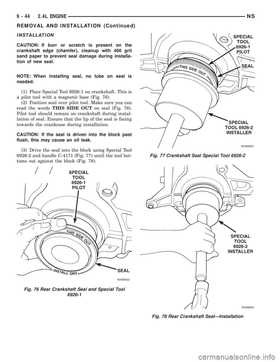
(1) Place Special Tool 6926-1 on crankshaft. This is
a pilot tool with a magnetic base (Fig. 76).
(2) Position seal over pilot tool. Make sure you can
read the wordsTHIS SIDE OUTon seal (Fig. 76).
Pilot tool should remain on crankshaft during instal-
lation of seal. Ensure that the lip of the seal is facing
towards the crankcase during installation.
CAUTION: If the seal is driven into the block past
flush, this may cause an oil leak.
(3) Drive the seal into the block using Special Tool
6926-2 and handle C-4171 (Fig. 77) until the tool bot-
toms out against the block (Fig. 78).
Fig. 76 Rear Crankshaft Seal and Special Tool
6926-1
Fig. 77 Crankshaft Seal Special Tool 6926-2
Fig. 78 Rear Crankshaft SealÐInstallation
9 - 44 2.4L ENGINENS
REMOVAL AND INSTALLATION (Continued)
Page 1095 of 1938
OIL PAN
REMOVAL
(1) Raise vehicle on hoist and drain engine oil.
(2) Remove front engine mount bracket from
engine and insulator mount.
(3) Remove bolts attaching bending strut to engine
and transaxle.
(4) Remove bolts attaching collar and bending
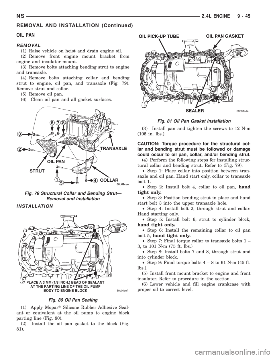
strut to engine, oil pan, and transaxle (Fig. 79).
Remove strut and collar.
(5) Remove oil pan.
(6) Clean oil pan and all gasket surfaces.
INSTALLATION
(1) Apply MopartSilicone Rubber Adhesive Seal-
ant or equivalent at the oil pump to engine block
parting line (Fig. 80).
(2) Install the oil pan gasket to the block (Fig.
81).(3) Install pan and tighten the screws to 12 N´m
(105 in. lbs.).
CAUTION: Torque procedure for the structural col-
lar and bending strut must be followed or damage
could occur to oil pan, collar, and/or bending strut.
(4) Perform the following steps for installing struc-
tural collar and bending strut. Refer to (Fig. 79):
²Step 1: Place collar into position between tran-
saxle and oil pan. Hand start only, collar to transaxle
bolt 1.
²Step 2: Install bolt 4, collar to oil pan,hand
tight only.
²Step 3: Position bending strut in place and hand
start bolt 3 into the upper transaxle hole.
²Step 4: Install bolt 2, through strut and collar.
Hand starting only.
²Step 5: Install bolt 6, strut to cylinder block,
hand tight only.
²Step 6: Install the remaining collar to oil pan
bolt 5,hand tight only.
²Step 7: Final torque collar to transaxle bolts 1 ±
3, to 101 N´m (75 ft. lbs.)
²Step 8: Install bolts 7 and 8, through strut and
into cylinder block.
²Step 9: Final torque bolts4±8to61N´m(45ft.
lbs.).
(5) Install front mount bracket to engine and front
insulator. Refer to procedure in the section.
(6) Lower vehicle and fill engine crankcase with
proper oil to correct level.
Fig. 79 Structural Collar and Bending StrutÐ
Removal and Installation
Fig. 80 Oil Pan Sealing
Fig. 81 Oil Pan Gasket Installation
NS2.4L ENGINE 9 - 45
REMOVAL AND INSTALLATION (Continued)
Page 1096 of 1938
CRANKSHAFT
REMOVAL
NOTE: Crankshaft can not be removed when
engine is in vehicle.
(1) Remove oil filter and oil pan. Refer to proce-
dure outlined in this section.
(2) Remove Timing Belt Cover, Timing Belt and
Oil Pump. Refer to procedure outlined in this section.
(3) Remove Balance Shafts Assembly. Refer to pro-
cedure outlined in this section.
(4) Remove all main bearing cap bedplate bolts
from the engine block. Refer to procedure outlined in
this section.
(5) Using a mallet gently tap the bedplate loose
from the engine block dowel pins.
CAUTION: Do not pry up on one side of the bed-
plate. Damage may occur to cylinder block to bed-
plate alignment and thrust bearing.
(6) Bedplate should be removed evenly from the
cylinder block dowel pins to prevent damage to the
dowel pins and thrust bearing.
(7) Lift out crankshaft from cylinder block. Do not
damage the main bearings or journals when remov-
ing the crankshaft.
INSTALLATION
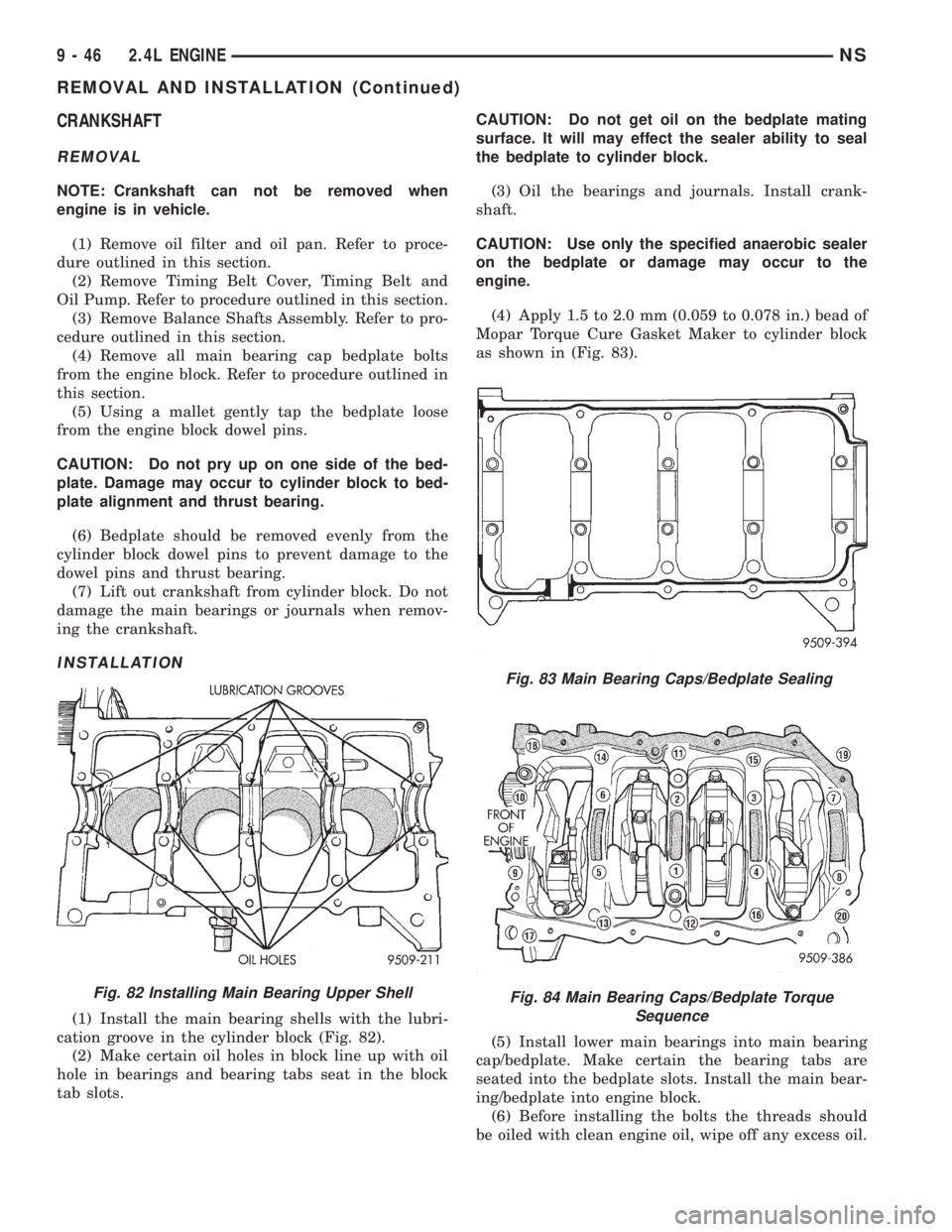
(1) Install the main bearing shells with the lubri-
cation groove in the cylinder block (Fig. 82).
(2) Make certain oil holes in block line up with oil
hole in bearings and bearing tabs seat in the block
tab slots.CAUTION: Do not get oil on the bedplate mating
surface. It will may effect the sealer ability to seal
the bedplate to cylinder block.
(3) Oil the bearings and journals. Install crank-
shaft.
CAUTION: Use only the specified anaerobic sealer
on the bedplate or damage may occur to the
engine.
(4) Apply 1.5 to 2.0 mm (0.059 to 0.078 in.) bead of
Mopar Torque Cure Gasket Maker to cylinder block
as shown in (Fig. 83).
(5) Install lower main bearings into main bearing
cap/bedplate. Make certain the bearing tabs are
seated into the bedplate slots. Install the main bear-
ing/bedplate into engine block.
(6) Before installing the bolts the threads should
be oiled with clean engine oil, wipe off any excess oil.
Fig. 82 Installing Main Bearing Upper Shell
Fig. 83 Main Bearing Caps/Bedplate Sealing
Fig. 84 Main Bearing Caps/Bedplate Torque
Sequence
9 - 46 2.4L ENGINENS
REMOVAL AND INSTALLATION (Continued)
Page 1097 of 1938
(7) Install main bearing bedplate to engine block
bolts 11, 17 and 20 finger tight. Tighten these bolts
down together until the bedplate contacts the cylin-
der block.
(8) To ensure correct thrust bearing alignment per-
form the following steps:
²Step 1: Rotate crankshaft until number 4 pis-
ton is at TDC.
²Step 2: Move crankshaft rearward to limits of
travel.
²Step 3: Then, move crankshaft forward to lim-
its of travel.
²Step 4: Wedge an appropraite tool between the
rear of the cylinder block(NOT BED PLATE)and
the rear crankshaft counterweight. This will hold the
crankshaft in it's furthest forward position.
²Step 5: Install and tighten bolts (1-10) in
sequence shown in (Fig. 84) to 41 Nzm (30 ft. lbs.).
²Step 6: Remove wedge tool used to hold crank-
shaft.
(9) Tighten bolts (1-10) again to 41 Nzm (30 ft. lbs)
+ 1/4 turn in sequence shown in (Fig. 84).
(10) Install main bearing bedplate to engine block
bolts (11-20), and torque each bolt to 28 Nzm (20 ft.
lbs.) in sequence shown in (Fig. 84).
(11) After the main bearing bedplate is installed,
check the crankshaft turning torque. The turning
torque should not exceed 5.6 Nzm (50 in. lbs.).
OIL FILTER
CAUTION: When servicing the oil filter avoid
deforming the filter can by installing the remove/in-
stall tool band strap against the can to base lock
seam. The lock seam joining the can to the base is
reinforced by the base plate.(1) Turn counterclockwise to remove.
(2) To install, lubricate new filter gasket. Check
filter mounting surface. The surface must be smooth,
flat and free of debris or old pieces of rubber. Screw
filter on until the gasket contacts base. Tighten to 21
N´m (15 ft. lbs.).
OIL PUMP
REMOVAL
(1) Disconnect negative cable from battery.
(2) Remove Timing Belt. Refer to procedure out-
lined in this section.
(3) Remove Oil Pan. Refer to procedure outlined in
this section.
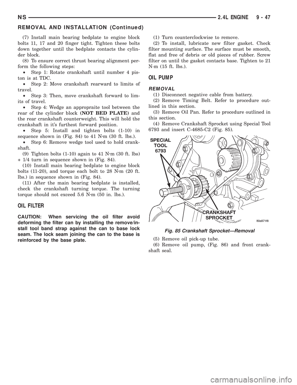
(4) Remove Crankshaft Sprocket using Special Tool
6793 and insert C-4685-C2 (Fig. 85).
(5) Remove oil pick-up tube.
(6) Remove oil pump, (Fig. 86) and front crank-
shaft seal.
Fig. 85 Crankshaft SprocketÐRemoval
NS2.4L ENGINE 9 - 47
REMOVAL AND INSTALLATION (Continued)
Page 1098 of 1938
INSTALLATION
(1) Make sure all surfaces are clean and free of oil
and dirt.
(2) Apply MopartGasket Maker to oil pump as
shown in (Fig. 87). Install oil ring into oil pump body
discharge passage.
(3) Prime oil pump before installation.(4) Align oil pump rotor flats with flats on crank-
shaft as you install the oil pump to the block.
NOTE: Front crankshaft seal MUST be out of pump
to align, or damage may result.
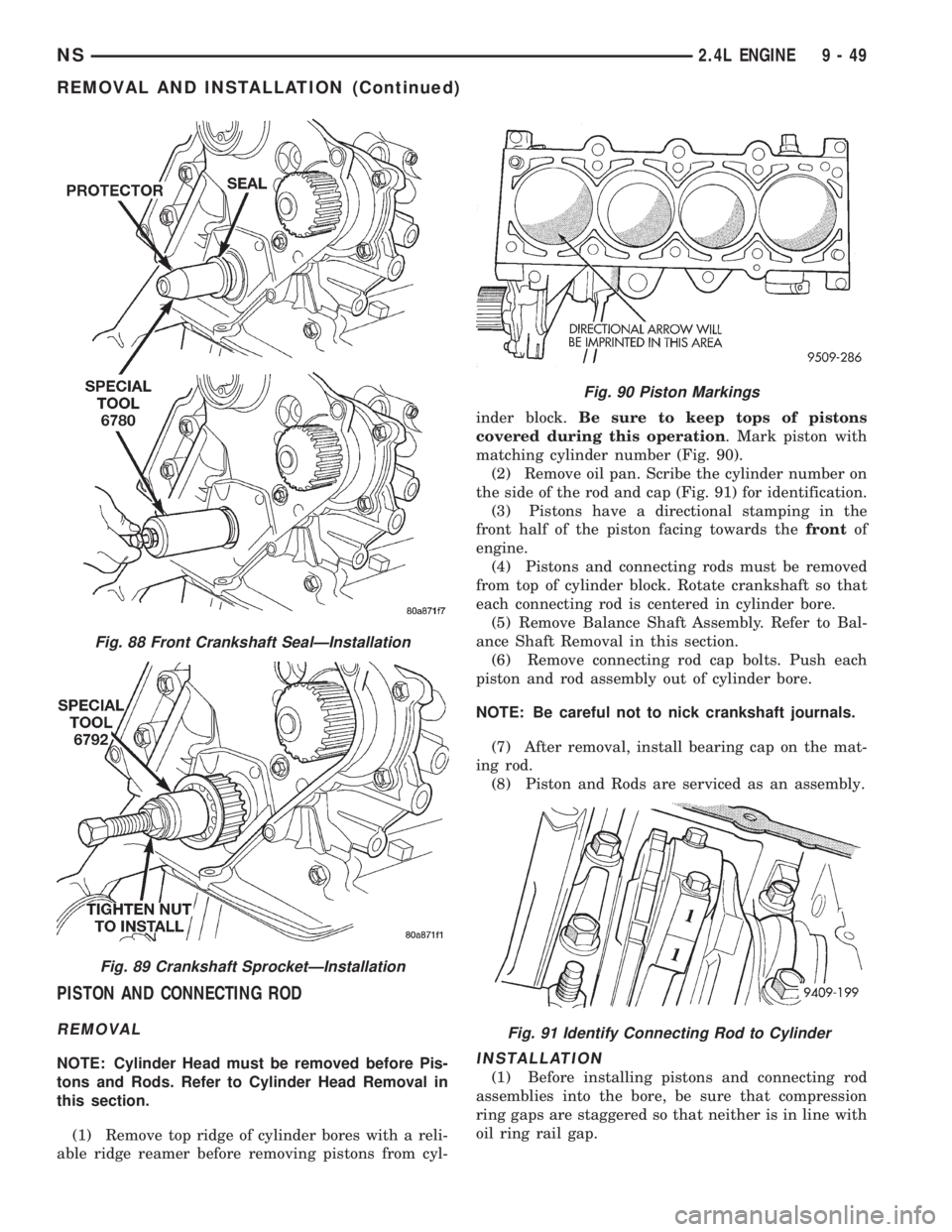
(5) Install new front crankshaft seal using Special
Tool 6780 (Fig. 88).
(6) Install crankshaft sprocket, using Special Tool
6792 (Fig. 89).
(7) Install oil pump pick-up tube.
CAUTION: Installation and torque procedure for the
collar must be followed or damage could occur to
oil pan or collar.
(8) Install oil pan and collar. Refer to procedure
outlined in this section.
(9) Install Timing Belt. Refer to procedure outlined
in this section.
Fig. 86 Oil Pump and Pick-up Tube
Fig. 87 Oil Pump Sealing
9 - 48 2.4L ENGINENS
REMOVAL AND INSTALLATION (Continued)
Page 1099 of 1938
PISTON AND CONNECTING ROD
REMOVAL
NOTE: Cylinder Head must be removed before Pis-
tons and Rods. Refer to Cylinder Head Removal in
this section.
(1) Remove top ridge of cylinder bores with a reli-
able ridge reamer before removing pistons from cyl-inder block.Be sure to keep tops of pistons
covered during this operation. Mark piston with
matching cylinder number (Fig. 90).
(2) Remove oil pan. Scribe the cylinder number on
the side of the rod and cap (Fig. 91) for identification.
(3) Pistons have a directional stamping in the
front half of the piston facing towards thefrontof
engine.
(4) Pistons and connecting rods must be removed
from top of cylinder block. Rotate crankshaft so that
each connecting rod is centered in cylinder bore.
(5) Remove Balance Shaft Assembly. Refer to Bal-
ance Shaft Removal in this section.
(6) Remove connecting rod cap bolts. Push each
piston and rod assembly out of cylinder bore.
NOTE: Be careful not to nick crankshaft journals.
(7) After removal, install bearing cap on the mat-
ing rod.
(8) Piston and Rods are serviced as an assembly.INSTALLATION
(1) Before installing pistons and connecting rod
assemblies into the bore, be sure that compression
ring gaps are staggered so that neither is in line with
oil ring rail gap.
Fig. 88 Front Crankshaft SealÐInstallation
Fig. 89 Crankshaft SprocketÐInstallation
Fig. 90 Piston Markings
Fig. 91 Identify Connecting Rod to Cylinder
NS2.4L ENGINE 9 - 49
REMOVAL AND INSTALLATION (Continued)