1996 CHRYSLER VOYAGER engine
[x] Cancel search: enginePage 1084 of 1938
CYLINDER HEAD
REMOVAL
(1) Perform fuel system pressure release proce-
durebefore attempting any repairs.Refer to
Group 14, Fuel System for procedure.
(2) Disconnect negative battery cable. Drain cool-
ing system. Refer to Group 7, Cooling System for pro-
cedure.
(3) Remove air cleaner and disconnect all vacuum
lines, electrical wiring and fuel lines from throttle
body.
(4) Remove throttle linkage. Refer to Group 14,
Fuel System for procedures
(5) Remove accessory drive belts. Refer to Group
7, Cooling System for procedure.
(6) Remove power brake vacuum hose from intake
manifold.
(7) Raise vehicle and remove exhaust pipe from
manifold.(8) Remove power steering pump assembly and
set aside.
(9) Disconnect coil pack wiring connector and
remove coil pack and plug wires from engine.
(10) Remove cam sensor and fuel injectors wiring
connectors.
(11) Remove timing belt and camshaft sprocket.
Refer to procedure outlined in this section.
(12) Remove timing belt idler pulley and rear tim-
ing belt cover.
(13) Remove cylinder head cover using procedure
outlined in this section.
(14) Remove camshafts and cam followers. Refer to
procedures outlined in this section for procedures.
(15) Remove cylinder head bolts and remove cyl-
inder head from engine block.
(16) Inspect and clean cylinder head. Refer to
Cleaning and Inspection outlined in this section for
procedures.
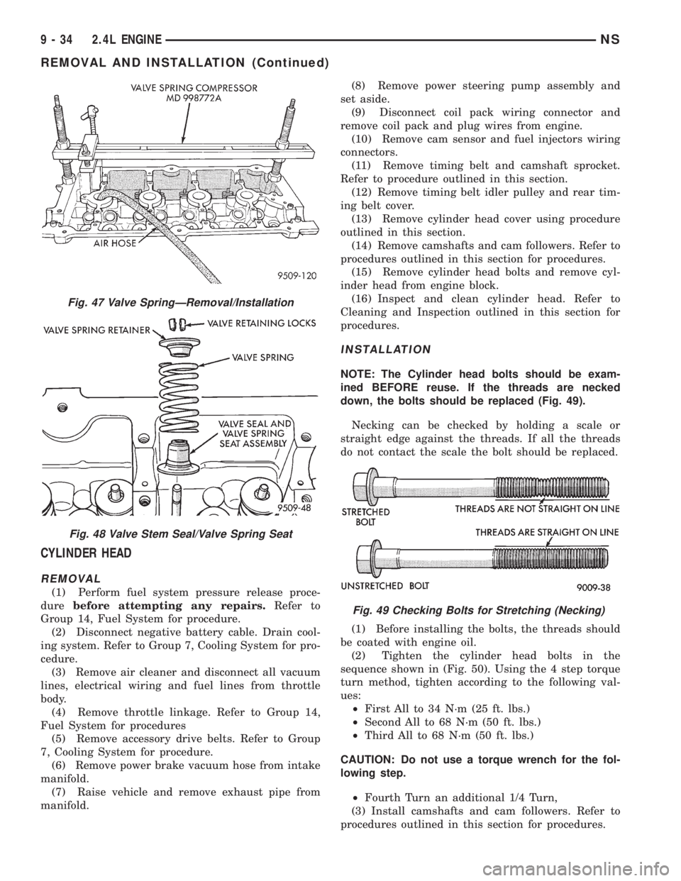
INSTALLATION
NOTE: The Cylinder head bolts should be exam-
ined BEFORE reuse. If the threads are necked
down, the bolts should be replaced (Fig. 49).
Necking can be checked by holding a scale or
straight edge against the threads. If all the threads
do not contact the scale the bolt should be replaced.
(1) Before installing the bolts, the threads should
be coated with engine oil.
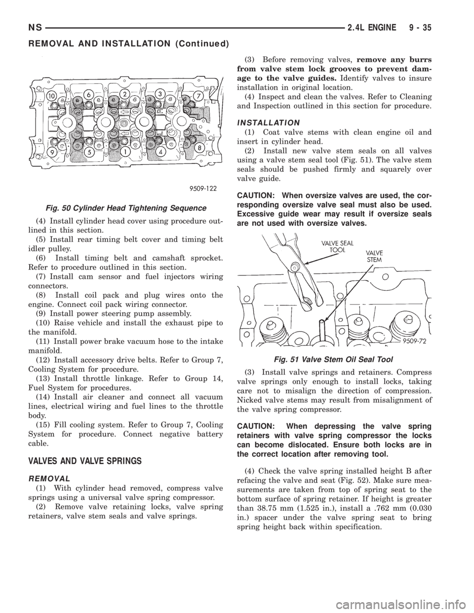
(2) Tighten the cylinder head bolts in the
sequence shown in (Fig. 50). Using the 4 step torque
turn method, tighten according to the following val-
ues:
²First All to 34 N´m (25 ft. lbs.)
²Second All to 68 N´m (50 ft. lbs.)
²Third All to 68 N´m (50 ft. lbs.)
CAUTION: Do not use a torque wrench for the fol-
lowing step.
²Fourth Turn an additional 1/4 Turn,
(3) Install camshafts and cam followers. Refer to
procedures outlined in this section for procedures.
Fig. 47 Valve SpringÐRemoval/Installation
Fig. 48 Valve Stem Seal/Valve Spring Seat
Fig. 49 Checking Bolts for Stretching (Necking)
9 - 34 2.4L ENGINENS
REMOVAL AND INSTALLATION (Continued)
Page 1085 of 1938
(4) Install cylinder head cover using procedure out-
lined in this section.
(5) Install rear timing belt cover and timing belt
idler pulley.
(6) Install timing belt and camshaft sprocket.
Refer to procedure outlined in this section.
(7) Install cam sensor and fuel injectors wiring
connectors.
(8) Install coil pack and plug wires onto the
engine. Connect coil pack wiring connector.
(9) Install power steering pump assembly.
(10) Raise vehicle and install the exhaust pipe to
the manifold.
(11) Install power brake vacuum hose to the intake
manifold.
(12) Install accessory drive belts. Refer to Group 7,
Cooling System for procedure.
(13) Install throttle linkage. Refer to Group 14,
Fuel System for procedures.
(14) Install air cleaner and connect all vacuum
lines, electrical wiring and fuel lines to the throttle
body.
(15) Fill cooling system. Refer to Group 7, Cooling
System for procedure. Connect negative battery
cable.
VALVES AND VALVE SPRINGS
REMOVAL
(1) With cylinder head removed, compress valve
springs using a universal valve spring compressor.
(2) Remove valve retaining locks, valve spring
retainers, valve stem seals and valve springs.(3) Before removing valves,remove any burrs
from valve stem lock grooves to prevent dam-
age to the valve guides.Identify valves to insure
installation in original location.
(4) Inspect and clean the valves. Refer to Cleaning
and Inspection outlined in this section for procedure.
INSTALLATION
(1) Coat valve stems with clean engine oil and
insert in cylinder head.
(2) Install new valve stem seals on all valves
using a valve stem seal tool (Fig. 51). The valve stem
seals should be pushed firmly and squarely over
valve guide.
CAUTION: When oversize valves are used, the cor-
responding oversize valve seal must also be used.
Excessive guide wear may result if oversize seals
are not used with oversize valves.
(3) Install valve springs and retainers. Compress
valve springs only enough to install locks, taking
care not to misalign the direction of compression.
Nicked valve stems may result from misalignment of
the valve spring compressor.
CAUTION: When depressing the valve spring
retainers with valve spring compressor the locks
can become dislocated. Ensure both locks are in
the correct location after removing tool.
(4) Check the valve spring installed height B after
refacing the valve and seat (Fig. 52). Make sure mea-
surements are taken from top of spring seat to the
bottom surface of spring retainer. If height is greater
than 38.75 mm (1.525 in.), install a .762 mm (0.030
in.) spacer under the valve spring seat to bring
spring height back within specification.
Fig. 50 Cylinder Head Tightening Sequence
Fig. 51 Valve Stem Oil Seal Tool
NS2.4L ENGINE 9 - 35
REMOVAL AND INSTALLATION (Continued)
Page 1086 of 1938
VIBRATION DAMPER
REMOVAL
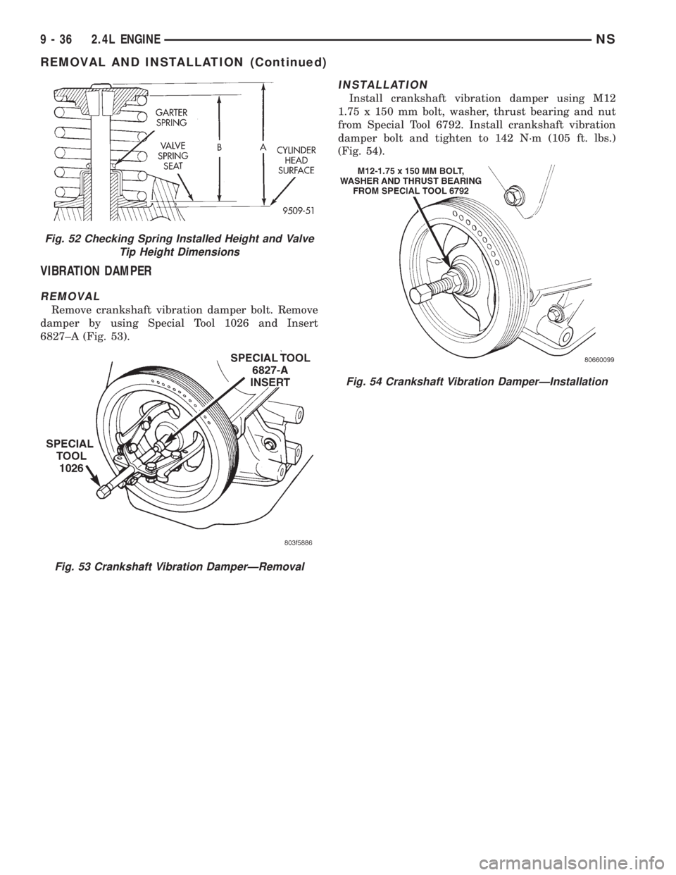
Remove crankshaft vibration damper bolt. Remove
damper by using Special Tool 1026 and Insert
6827±A (Fig. 53).
INSTALLATION
Install crankshaft vibration damper using M12
1.75 x 150 mm bolt, washer, thrust bearing and nut
from Special Tool 6792. Install crankshaft vibration
damper bolt and tighten to 142 N´m (105 ft. lbs.)
(Fig. 54).
Fig. 52 Checking Spring Installed Height and Valve
Tip Height Dimensions
Fig. 53 Crankshaft Vibration DamperÐRemoval
Fig. 54 Crankshaft Vibration DamperÐInstallation
9 - 36 2.4L ENGINENS
REMOVAL AND INSTALLATION (Continued)
Page 1087 of 1938
TIMING BELT COVER
FRONT COVER
REMOVAL
(1) Remove crankshaft damper. Refer to crank-
shaft damper removal for procedure.
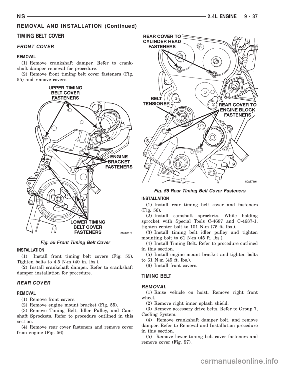
(2) Remove front timing belt cover fasteners (Fig.
55) and remove covers.
INSTALLATION
(1) Install front timing belt covers (Fig. 55).
Tighten bolts to 4.5 N´m (40 in. lbs.).
(2) Install crankshaft damper. Refer to crankshaft
damper installation for procedure.
REAR COVER
REMOVAL
(1) Remove front covers.
(2) Remove engine mount bracket (Fig. 55).
(3) Remove Timing Belt, Idler Pulley, and Cam-
shaft Sprockets. Refer to procedure outlined in this
section.
(4) Remove rear cover fasteners and remove cover
from engine (Fig. 56).INSTALLATION
(1) Install rear timing belt cover and fasteners
(Fig. 56).
(2) Install camshaft sprockets. While holding
sprocket with Special Tools C-4687 and C-4687-1,
tighten center bolt to 101 N´m (75 ft. lbs.).
(3) Install timing belt idler pulley and tighten
mounting bolt to 61 N´m (45 ft. lbs.).
(4) Install Timing Belt. Refer to procedure outlined
in this section.
(5) Install engine mount bracket and tighten bolts
to 61 N´m (45 ft. lbs.).
(6) Install front covers.
TIMING BELT
REMOVAL
(1) Raise vehicle on hoist. Remove right front
wheel.
(2) Remove right inner splash shield.
(3) Remove accessory drive belts. Refer to Group 7,
Cooling System.
(4) Remove crankshaft damper bolt, and remove
damper. Refer to Removal and Installation procedure
in this section.
(5) Remove lower timing belt cover fasteners and
remove cover (Fig. 57).
Fig. 55 Front Timing Belt Cover
Fig. 56 Rear Timing Belt Cover Fasteners
NS2.4L ENGINE 9 - 37
REMOVAL AND INSTALLATION (Continued)
Page 1088 of 1938
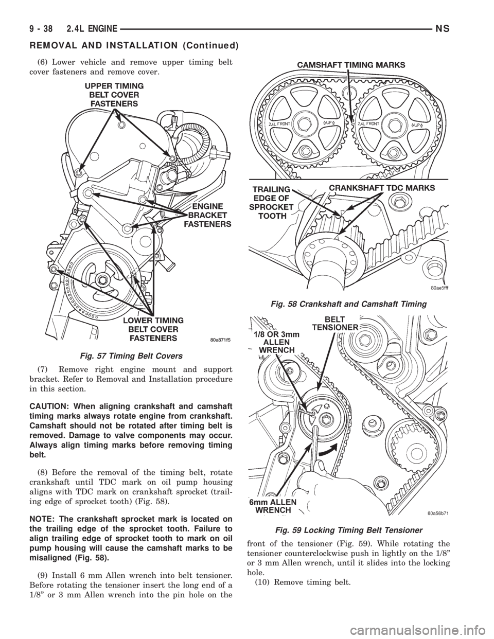
(6) Lower vehicle and remove upper timing belt
cover fasteners and remove cover.
(7) Remove right engine mount and support
bracket. Refer to Removal and Installation procedure
in this section.
CAUTION: When aligning crankshaft and camshaft
timing marks always rotate engine from crankshaft.
Camshaft should not be rotated after timing belt is
removed. Damage to valve components may occur.
Always align timing marks before removing timing
belt.
(8) Before the removal of the timing belt, rotate
crankshaft until TDC mark on oil pump housing
aligns with TDC mark on crankshaft sprocket (trail-
ing edge of sprocket tooth) (Fig. 58).
NOTE: The crankshaft sprocket mark is located on
the trailing edge of the sprocket tooth. Failure to
align trailing edge of sprocket tooth to mark on oil
pump housing will cause the camshaft marks to be
misaligned (Fig. 58).
(9) Install 6 mm Allen wrench into belt tensioner.
Before rotating the tensioner insert the long end of a
1/8º or 3 mm Allen wrench into the pin hole on thefront of the tensioner (Fig. 59). While rotating the
tensioner counterclockwise push in lightly on the 1/8º
or 3 mm Allen wrench, until it slides into the locking
hole.
(10) Remove timing belt.
Fig. 57 Timing Belt Covers
Fig. 58 Crankshaft and Camshaft Timing
Fig. 59 Locking Timing Belt Tensioner
9 - 38 2.4L ENGINENS
REMOVAL AND INSTALLATION (Continued)
Page 1089 of 1938
CAUTION: If timing belt was damaged due to incor-
rect tracking (alignment), the belt tensioner assem-
bly must be replace. Refer to Timing Belt Tensioner
Assembly Removal and Installation procedure out-
lined in this section.
INSTALLATION
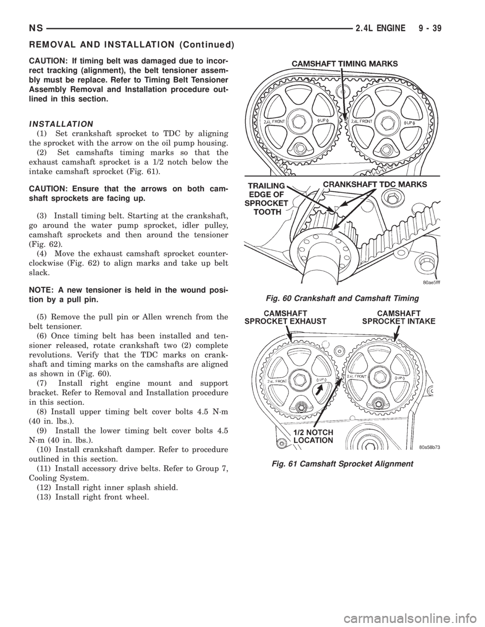
(1) Set crankshaft sprocket to TDC by aligning
the sprocket with the arrow on the oil pump housing.
(2) Set camshafts timing marks so that the
exhaust camshaft sprocket is a 1/2 notch below the
intake camshaft sprocket (Fig. 61).
CAUTION: Ensure that the arrows on both cam-
shaft sprockets are facing up.
(3) Install timing belt. Starting at the crankshaft,
go around the water pump sprocket, idler pulley,
camshaft sprockets and then around the tensioner
(Fig. 62).
(4) Move the exhaust camshaft sprocket counter-
clockwise (Fig. 62) to align marks and take up belt
slack.
NOTE: A new tensioner is held in the wound posi-
tion by a pull pin.
(5) Remove the pull pin or Allen wrench from the
belt tensioner.
(6) Once timing belt has been installed and ten-
sioner released, rotate crankshaft two (2) complete
revolutions. Verify that the TDC marks on crank-
shaft and timing marks on the camshafts are aligned
as shown in (Fig. 60).
(7) Install right engine mount and support
bracket. Refer to Removal and Installation procedure
in this section.
(8) Install upper timing belt cover bolts 4.5 N´m
(40 in. lbs.).
(9) Install the lower timing belt cover bolts 4.5
N´m (40 in. lbs.).
(10) Install crankshaft damper. Refer to procedure
outlined in this section.
(11) Install accessory drive belts. Refer to Group 7,
Cooling System.
(12) Install right inner splash shield.
(13) Install right front wheel.
Fig. 60 Crankshaft and Camshaft Timing
Fig. 61 Camshaft Sprocket Alignment
NS2.4L ENGINE 9 - 39
REMOVAL AND INSTALLATION (Continued)
Page 1090 of 1938
TIMING BELT TENSIONER ASSEMBLY
REMOVAL
(1) Remove timing belt. Refer to Removal and
Installation procedure in this section.
(2) Remove timing belt idler pulley.
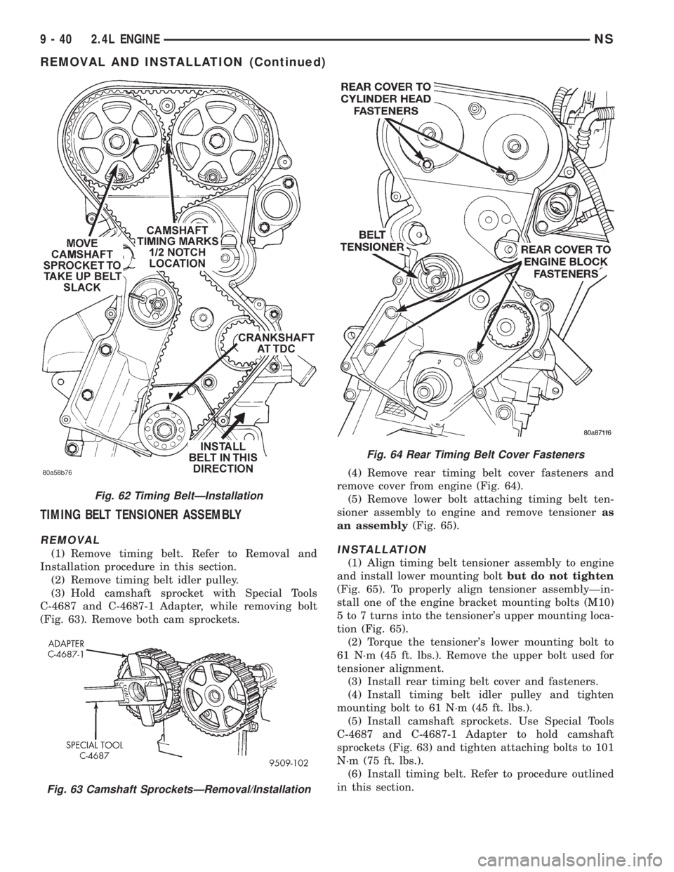
(3) Hold camshaft sprocket with Special Tools
C-4687 and C-4687-1 Adapter, while removing bolt
(Fig. 63). Remove both cam sprockets.(4) Remove rear timing belt cover fasteners and
remove cover from engine (Fig. 64).
(5) Remove lower bolt attaching timing belt ten-
sioner assembly to engine and remove tensioneras
an assembly(Fig. 65).INSTALLATION
(1) Align timing belt tensioner assembly to engine
and install lower mounting boltbut do not tighten
(Fig. 65). To properly align tensioner assemblyÐin-
stall one of the engine bracket mounting bolts (M10)
5 to 7 turns into the tensioner's upper mounting loca-
tion (Fig. 65).
(2) Torque the tensioner's lower mounting bolt to
61 N´m (45 ft. lbs.). Remove the upper bolt used for
tensioner alignment.
(3) Install rear timing belt cover and fasteners.
(4) Install timing belt idler pulley and tighten
mounting bolt to 61 N´m (45 ft. lbs.).
(5) Install camshaft sprockets. Use Special Tools
C-4687 and C-4687-1 Adapter to hold camshaft
sprockets (Fig. 63) and tighten attaching bolts to 101
N´m (75 ft. lbs.).
(6) Install timing belt. Refer to procedure outlined
in this section.
Fig. 62 Timing BeltÐInstallation
Fig. 63 Camshaft SprocketsÐRemoval/Installation
Fig. 64 Rear Timing Belt Cover Fasteners
9 - 40 2.4L ENGINENS
REMOVAL AND INSTALLATION (Continued)
Page 1091 of 1938
CAMSHAFT OIL SEALÐFRONT
REMOVAL
(1) Remove front timing belt covers and timing
belt. Refer to procedures outlined in this section.
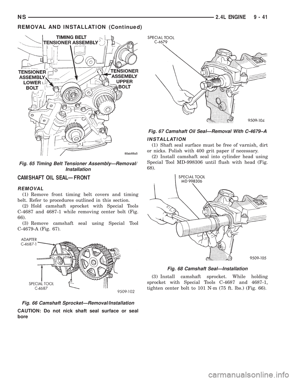
(2) Hold camshaft sprocket with Special Tools
C-4687 and 4687-1 while removing center bolt (Fig.
66).
(3) Remove camshaft seal using Special Tool
C-4679-A (Fig. 67).
CAUTION: Do not nick shaft seal surface or seal
bore
INSTALLATION
(1) Shaft seal surface must be free of varnish, dirt
or nicks. Polish with 400 grit paper if necessary.
(2) Install camshaft seal into cylinder head using
Special Tool MD-998306 until flush with head (Fig.
68).
(3) Install camshaft sprocket. While holding
sprocket with Special Tools C-4687 and 4687-1,
tighten center bolt to 101 N´m (75 ft. lbs.) (Fig. 66).
Fig. 65 Timing Belt Tensioner AssemblyÐRemoval/
Installation
Fig. 66 Camshaft SprocketÐRemoval/Installation
Fig. 67 Camshaft Oil SealÐRemoval With C-4679±A
Fig. 68 Camshaft SealÐInstallation
NS2.4L ENGINE 9 - 41
REMOVAL AND INSTALLATION (Continued)