1996 CHRYSLER VOYAGER engine
[x] Cancel search: enginePage 1076 of 1938
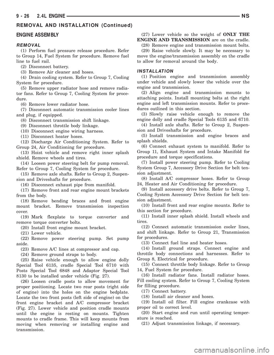
ENGINE ASSEMBLY
REMOVAL
(1) Perform fuel pressure release procedure. Refer
to Group 14, Fuel System for procedure. Remove fuel
line to fuel rail.
(2) Disconnect battery.
(3) Remove Air cleaner and hoses.
(4) Drain cooling system. Refer to Group 7, Cooling
System for procedure.
(5) Remove upper radiator hose and remove radia-
tor fans. Refer to Group 7, Cooling System for proce-
dure.
(6) Remove lower radiator hose.
(7) Disconnect automatic transmission cooler lines
and plug, if equipped.
(8) Disconnect transmission shift linkage.
(9) Disconnect throttle body linkage.
(10) Disconnect engine wiring harness.
(11) Disconnect heater hoses.
(12) Discharge Air Conditioning System. Refer to
Group 24, Air Conditioning for procedure.
(13) Hoist vehicle and remove right inner splash
shield. Remove wheels and tires.
(14) Loosen power steering belt for pump removal.
Refer to Group 7, Cooling System for procedure.
(15) Remove axle shafts. Refer to Group 2, Suspen-
sion and Driveshafts for procedure.
(16) Disconnect exhaust pipe from manifold.
(17) Remove front and rear engine mount brackets
from the body.
(18) Remove bending braces and front engine
mount bracket. Remove transmission inspection
cover.
(19) Mark flexplate to torque converter and
remove torque converter bolts.
(20) Install front engine mount bracket.
(21) Lower vehicle.
(22) Remove power steering pump. Set pump
aside.
(23) Remove A/C lines at compressor and cap.
(24) Remove ground straps to body.
(25) Raise vehicle enough to allow engine dolly
Special Tool 6135, cradle Special Tool 6710 with
Posts Special Tool 6848 and Adaptor Special Tool
8130 to be installed under vehicle (Fig. 27).
(26) Loosen cradle posts to allow movement for
proper positioning. Locate two rear posts (right side
of engine) into the holes on the engine bedplate.
Locate the two front posts (left side of engine) on the
front engine bracket and A/C compressor bracket
(Fig. 27). Lower vehicle and position cradle mounts
until the engine is resting on mounts. Tighten
mounts to cradle frame. This will keep mounts from
moving when removing or installing engine and
transmission.(27) Lower vehicle so the weight ofONLY THE
ENGINE AND TRANSMISSIONare on the cradle.
(28) Remove engine and transmission mount bolts.
(29) Raise vehicle slowly. It may be necessary to
move the engine/transmission assembly on the cradle
to allow for removal around the body.
INSTALLATION
(1) Position engine and transmission assembly
under vehicle and slowly lower the vehicle over the
engine and transmission.
(2) Align engine and transmission mounts to
attaching points. Install mounting bolts at the right
engine and left transmission mounts. Refer to proce-
dures outlined in this section.
(3) Slowly raise vehicle enough to remove the
engine dolly and cradle Special Tools 6135 and 6710.
(4) Install axle shafts. Refer to Group 2, Suspen-
sion and Driveshafts for procedure.
(5) Install transmission and engine braces and
splash shields.
(6) Connect exhaust system to manifold. Refer to
Group 11, Exhaust System and Intake Manifold for
procedure and torque specifications.
(7) Install power steering pump. Refer to Cooling
System Group 7, Accessory Drive Section for belt ten-
sion adjustment.
(8) Install A/C compressor hoses. Refer to Group
24, Heater and Air Conditioning for procedure.
(9) Install accessory drive belts. Refer to Group 7,
Cooling System Accessory Drive Section for belt ten-
sion adjustment.
(10) Install front and rear engine mounts. Refer to
this section for procedure.
(11) Install inner splash shield. Install wheels and
tires.
(12) Connect automatic transmission cooler lines,
and shift linkage. Refer to Group 21, Transmission
for procedures.
(13) Connect fuel line and heater hoses.
(14) Install ground straps. Connect engine and
throttle body connections and harnesses. Refer to
Group 8, Electrical for procedure.
(15) Connect throttle body linkage. Refer to Group
14, Fuel System for procedure.
(16) Install radiator fans. Install radiator hoses.
Fill cooling system. Refer to Group 7, Cooling System
for filling procedure.
(17) Connect battery.
(18) Install air cleaner and hoses.
(19) Install oil filter. Fill engine crankcase with
proper oil to correct level.
(20) Start engine and run until operating temper-
ature is reached.
(21) Adjust transmission linkage, if necessary.
9 - 26 2.4L ENGINENS
REMOVAL AND INSTALLATION (Continued)
Page 1077 of 1938
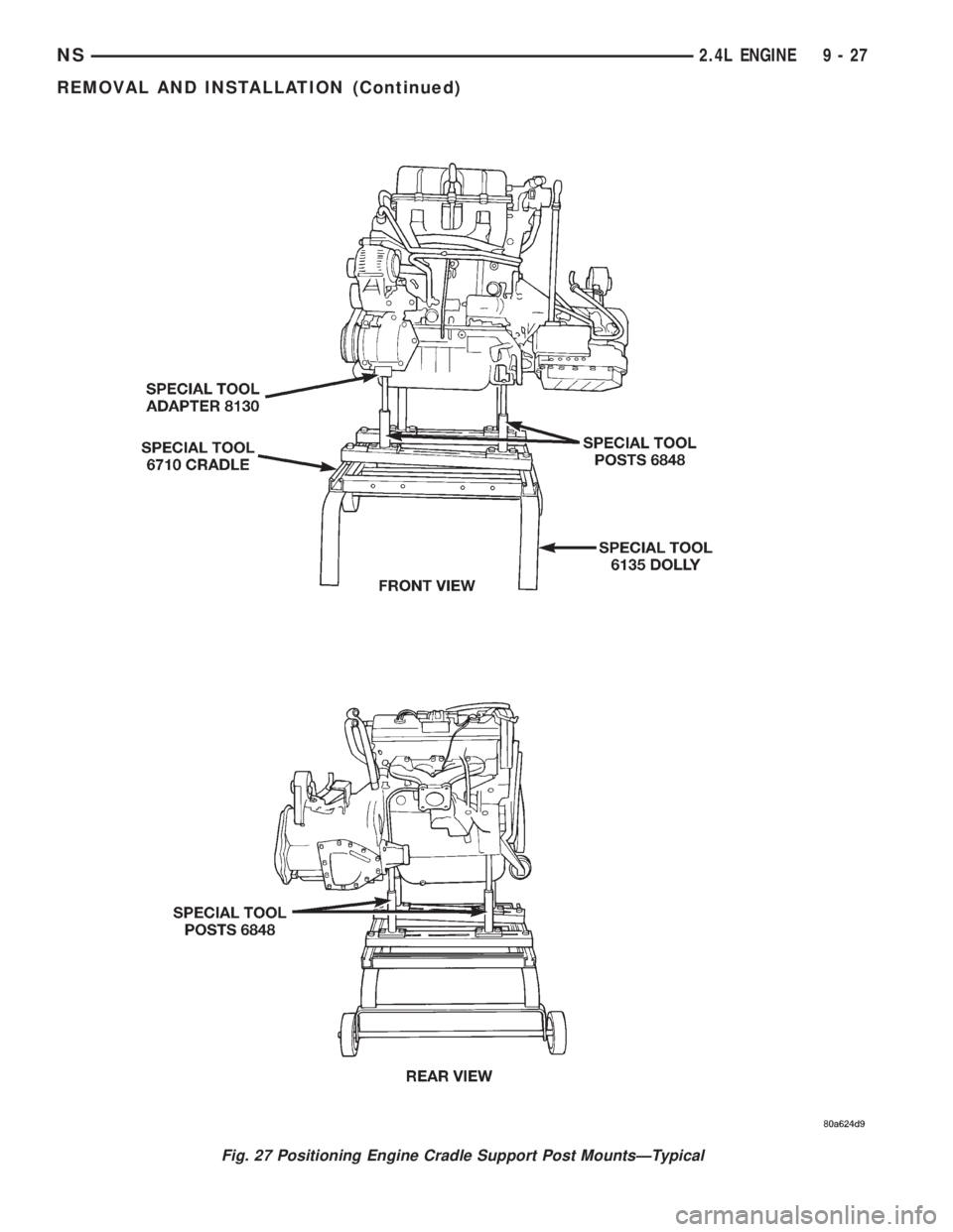
Fig. 27 Positioning Engine Cradle Support Post MountsÐTypical
NS2.4L ENGINE 9 - 27
REMOVAL AND INSTALLATION (Continued)
Page 1078 of 1938
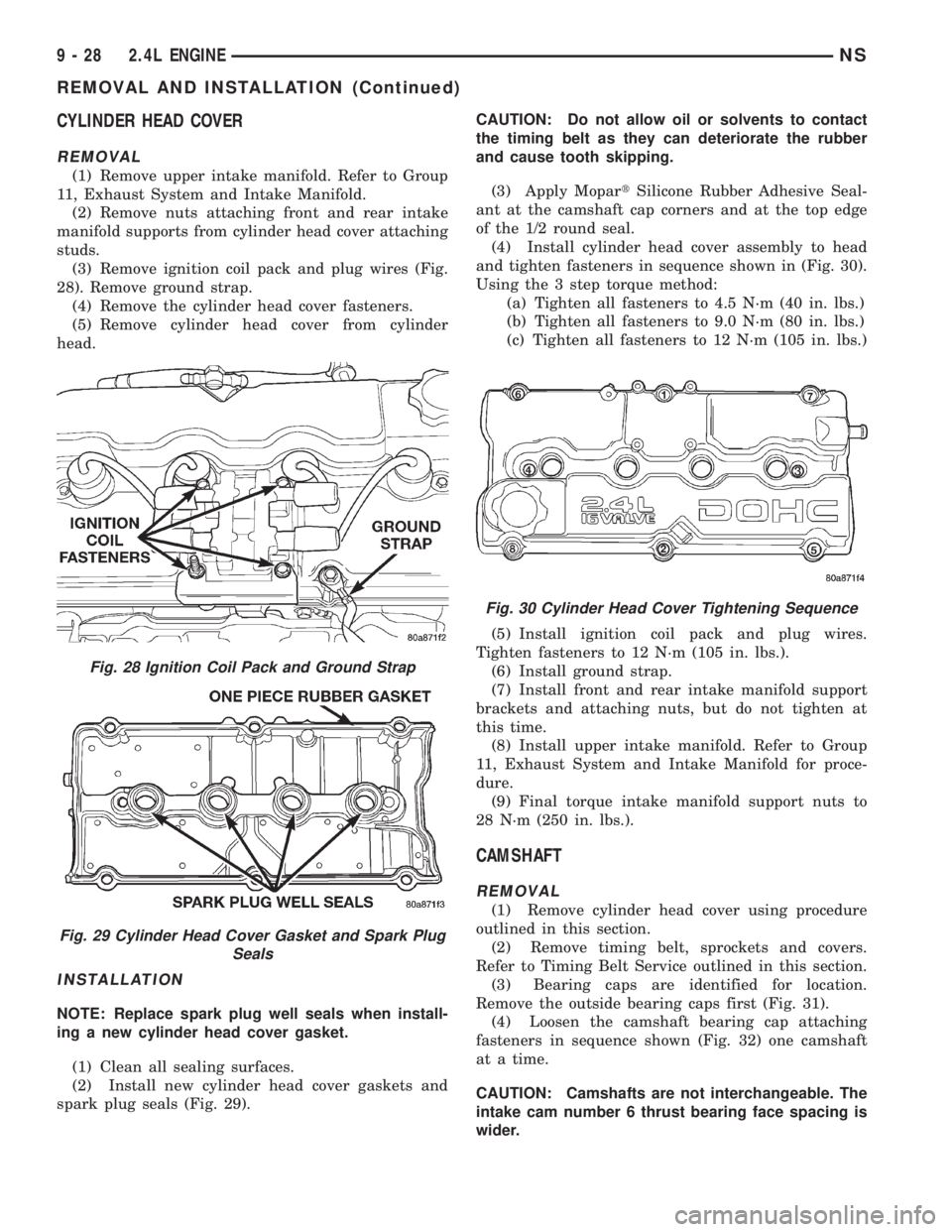
CYLINDER HEAD COVER
REMOVAL
(1) Remove upper intake manifold. Refer to Group
11, Exhaust System and Intake Manifold.
(2) Remove nuts attaching front and rear intake
manifold supports from cylinder head cover attaching
studs.
(3) Remove ignition coil pack and plug wires (Fig.
28). Remove ground strap.
(4) Remove the cylinder head cover fasteners.
(5) Remove cylinder head cover from cylinder
head.
INSTALLATION
NOTE: Replace spark plug well seals when install-
ing a new cylinder head cover gasket.
(1) Clean all sealing surfaces.
(2) Install new cylinder head cover gaskets and
spark plug seals (Fig. 29).CAUTION: Do not allow oil or solvents to contact
the timing belt as they can deteriorate the rubber
and cause tooth skipping.
(3) Apply MopartSilicone Rubber Adhesive Seal-
ant at the camshaft cap corners and at the top edge
of the 1/2 round seal.
(4) Install cylinder head cover assembly to head
and tighten fasteners in sequence shown in (Fig. 30).
Using the 3 step torque method:
(a) Tighten all fasteners to 4.5 N´m (40 in. lbs.)
(b) Tighten all fasteners to 9.0 N´m (80 in. lbs.)
(c) Tighten all fasteners to 12 N´m (105 in. lbs.)
(5) Install ignition coil pack and plug wires.
Tighten fasteners to 12 N´m (105 in. lbs.).
(6) Install ground strap.
(7) Install front and rear intake manifold support
brackets and attaching nuts, but do not tighten at
this time.
(8) Install upper intake manifold. Refer to Group
11, Exhaust System and Intake Manifold for proce-
dure.
(9) Final torque intake manifold support nuts to
28 N´m (250 in. lbs.).
CAMSHAFT
REMOVAL
(1) Remove cylinder head cover using procedure
outlined in this section.
(2) Remove timing belt, sprockets and covers.
Refer to Timing Belt Service outlined in this section.
(3) Bearing caps are identified for location.
Remove the outside bearing caps first (Fig. 31).
(4) Loosen the camshaft bearing cap attaching
fasteners in sequence shown (Fig. 32) one camshaft
at a time.
CAUTION: Camshafts are not interchangeable. The
intake cam number 6 thrust bearing face spacing is
wider.
Fig. 28 Ignition Coil Pack and Ground Strap
Fig. 29 Cylinder Head Cover Gasket and Spark Plug
Seals
Fig. 30 Cylinder Head Cover Tightening Sequence
9 - 28 2.4L ENGINENS
REMOVAL AND INSTALLATION (Continued)
Page 1079 of 1938
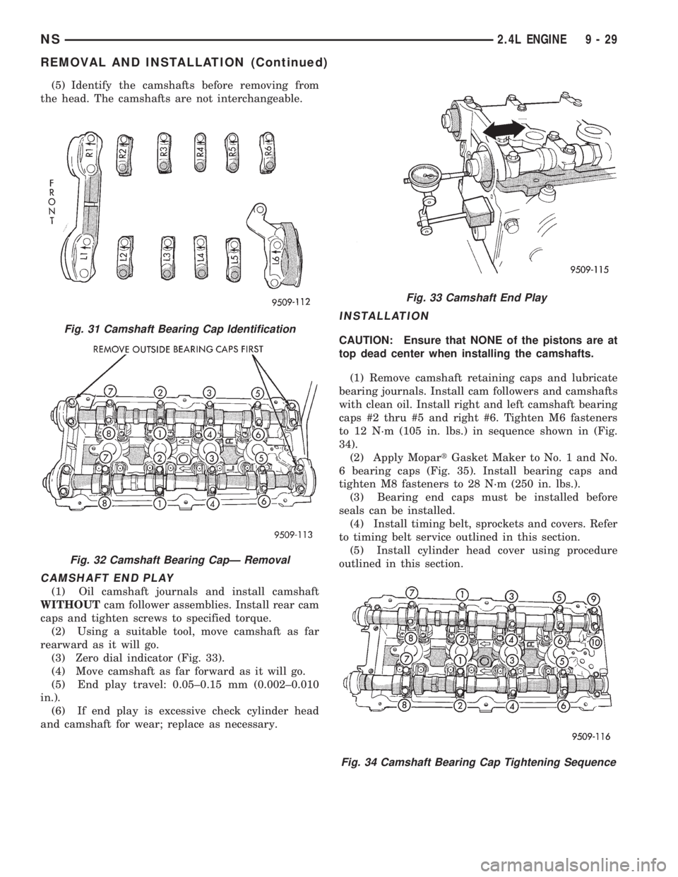
(5) Identify the camshafts before removing from
the head. The camshafts are not interchangeable.
CAMSHAFT END PLAY
(1) Oil camshaft journals and install camshaft
WITHOUTcam follower assemblies. Install rear cam
caps and tighten screws to specified torque.
(2) Using a suitable tool, move camshaft as far
rearward as it will go.
(3) Zero dial indicator (Fig. 33).
(4) Move camshaft as far forward as it will go.
(5) End play travel: 0.05±0.15 mm (0.002±0.010
in.).
(6) If end play is excessive check cylinder head
and camshaft for wear; replace as necessary.
INSTALLATION
CAUTION: Ensure that NONE of the pistons are at
top dead center when installing the camshafts.
(1) Remove camshaft retaining caps and lubricate
bearing journals. Install cam followers and camshafts
with clean oil. Install right and left camshaft bearing
caps #2 thru #5 and right #6. Tighten M6 fasteners
to 12 N´m (105 in. lbs.) in sequence shown in (Fig.
34).
(2) Apply MopartGasket Maker to No. 1 and No.
6 bearing caps (Fig. 35). Install bearing caps and
tighten M8 fasteners to 28 N´m (250 in. lbs.).
(3) Bearing end caps must be installed before
seals can be installed.
(4) Install timing belt, sprockets and covers. Refer
to timing belt service outlined in this section.
(5) Install cylinder head cover using procedure
outlined in this section.Fig. 31 Camshaft Bearing Cap Identification
Fig. 32 Camshaft Bearing CapÐ Removal
Fig. 33 Camshaft End Play
Fig. 34 Camshaft Bearing Cap Tightening Sequence
NS2.4L ENGINE 9 - 29
REMOVAL AND INSTALLATION (Continued)
Page 1080 of 1938
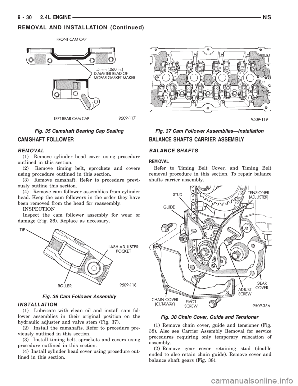
CAMSHAFT FOLLOWER
REMOVAL
(1) Remove cylinder head cover using procedure
outlined in this section.
(2) Remove timing belt, sprockets and covers
using procedure outlined in this section.
(3) Remove camshaft. Refer to procedure previ-
ously outline this section.
(4) Remove cam follower assemblies from cylinder
head. Keep the cam followers in the order they have
been removed from the head for reassembly.
INSPECTION
Inspect the cam follower assembly for wear or
damage (Fig. 36). Replace as necessary.
INSTALLATION
(1) Lubricate with clean oil and install cam fol-
lower assemblies in their original position on the
hydraulic adjuster and valve stem (Fig. 37).
(2) Install the camshafts. Refer to procedure pre-
viously outlined in this section.
(3) Install timing belt, sprockets and covers using
procedure outlined in this section.
(4) Install cylinder head cover using procedure out-
lined in this section.
BALANCE SHAFTS CARRIER ASSEMBLY
BALANCE SHAFTS
REMOVAL
Refer to Timing Belt Cover, and Timing Belt
removal procedure in this section. To repair balance
shafts carrier assembly.
(1) Remove chain cover, guide and tensioner (Fig.
38). Also see Carrier Assembly Removal for service
procedures requiring only temporary relocation of
assembly.
(2) Remove gear cover retaining stud (double
ended to also retain chain guide). Remove cover and
balance shaft gears (Fig. 38).
Fig. 35 Camshaft Bearing Cap Sealing
Fig. 36 Cam Follower Assembly
Fig. 37 Cam Follower AssembliesÐInstallation
Fig. 38 Chain Cover, Guide and Tensioner
9 - 30 2.4L ENGINENS
REMOVAL AND INSTALLATION (Continued)
Page 1081 of 1938
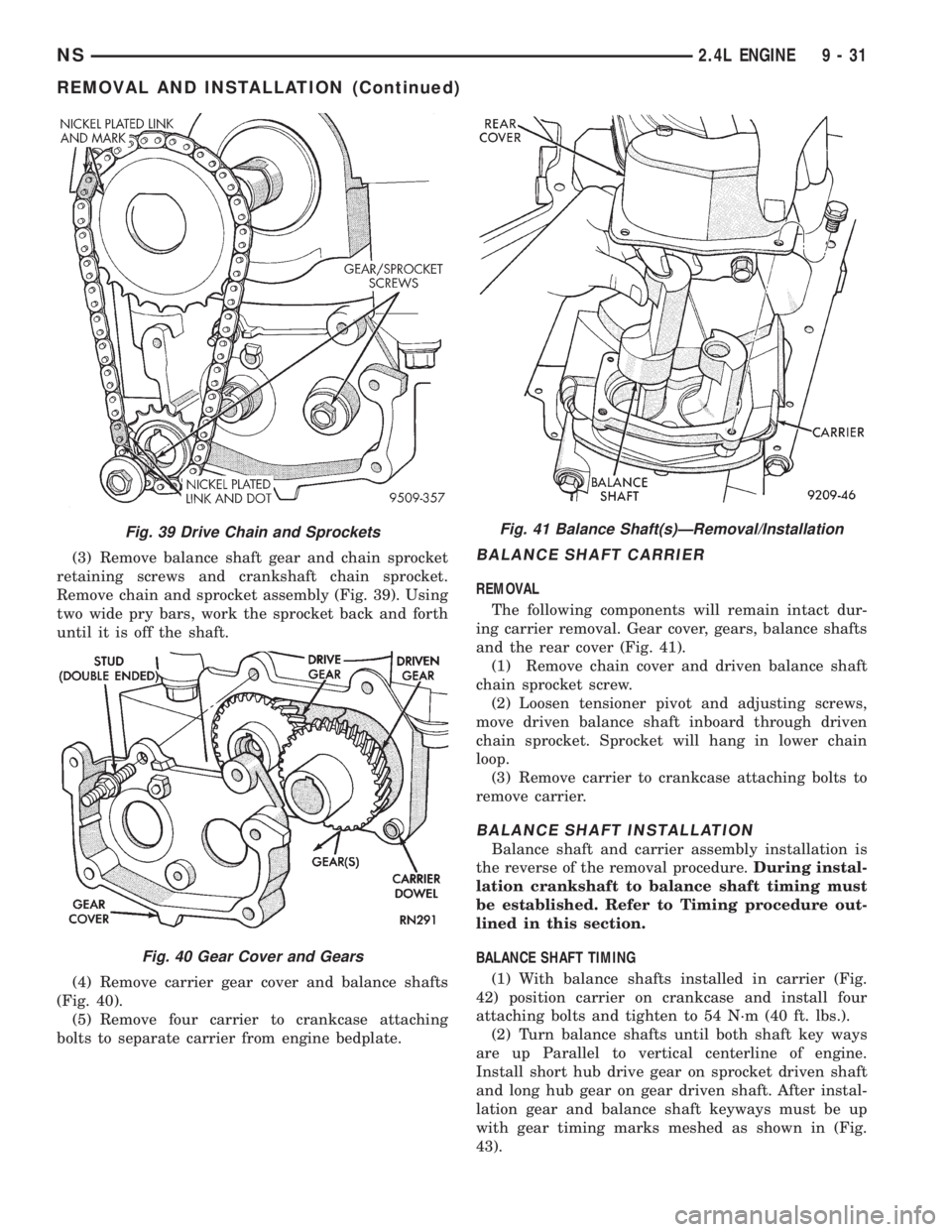
(3) Remove balance shaft gear and chain sprocket
retaining screws and crankshaft chain sprocket.
Remove chain and sprocket assembly (Fig. 39). Using
two wide pry bars, work the sprocket back and forth
until it is off the shaft.
(4) Remove carrier gear cover and balance shafts
(Fig. 40).
(5) Remove four carrier to crankcase attaching
bolts to separate carrier from engine bedplate.BALANCE SHAFT CARRIER
REMOVAL
The following components will remain intact dur-
ing carrier removal. Gear cover, gears, balance shafts
and the rear cover (Fig. 41).
(1) Remove chain cover and driven balance shaft
chain sprocket screw.
(2) Loosen tensioner pivot and adjusting screws,
move driven balance shaft inboard through driven
chain sprocket. Sprocket will hang in lower chain
loop.
(3) Remove carrier to crankcase attaching bolts to
remove carrier.
BALANCE SHAFT INSTALLATION
Balance shaft and carrier assembly installation is
the reverse of the removal procedure.During instal-
lation crankshaft to balance shaft timing must
be established. Refer to Timing procedure out-
lined in this section.
BALANCE SHAFT TIMING
(1) With balance shafts installed in carrier (Fig.
42) position carrier on crankcase and install four
attaching bolts and tighten to 54 N´m (40 ft. lbs.).
(2) Turn balance shafts until both shaft key ways
are up Parallel to vertical centerline of engine.
Install short hub drive gear on sprocket driven shaft
and long hub gear on gear driven shaft. After instal-
lation gear and balance shaft keyways must be up
with gear timing marks meshed as shown in (Fig.
43).
Fig. 39 Drive Chain and Sprockets
Fig. 40 Gear Cover and Gears
Fig. 41 Balance Shaft(s)ÐRemoval/Installation
NS2.4L ENGINE 9 - 31
REMOVAL AND INSTALLATION (Continued)
Page 1082 of 1938
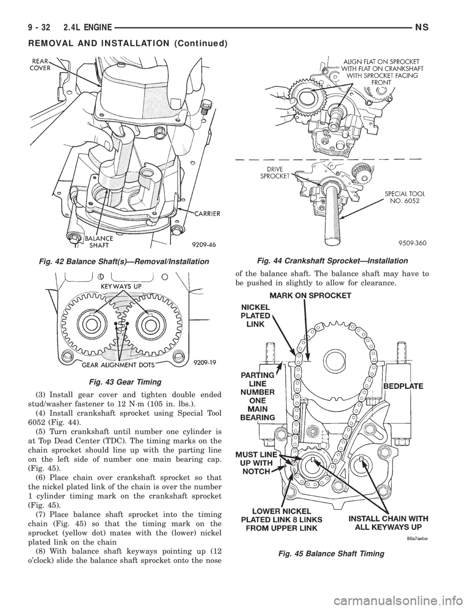
(3) Install gear cover and tighten double ended
stud/washer fastener to 12 N´m (105 in. lbs.).
(4) Install crankshaft sprocket using Special Tool
6052 (Fig. 44).
(5) Turn crankshaft until number one cylinder is
at Top Dead Center (TDC). The timing marks on the
chain sprocket should line up with the parting line
on the left side of number one main bearing cap.
(Fig. 45).
(6) Place chain over crankshaft sprocket so that
the nickel plated link of the chain is over the number
1 cylinder timing mark on the crankshaft sprocket
(Fig. 45).
(7) Place balance shaft sprocket into the timing
chain (Fig. 45) so that the timing mark on the
sprocket (yellow dot) mates with the (lower) nickel
plated link on the chain
(8) With balance shaft keyways pointing up (12
o'clock) slide the balance shaft sprocket onto the noseof the balance shaft. The balance shaft may have to
be pushed in slightly to allow for clearance.
Fig. 42 Balance Shaft(s)ÐRemoval/Installation
Fig. 43 Gear Timing
Fig. 44 Crankshaft SprocketÐInstallation
Fig. 45 Balance Shaft Timing
9 - 32 2.4L ENGINENS
REMOVAL AND INSTALLATION (Continued)
Page 1083 of 1938
NOTE: THE TIMING MARK ON THE SPROCKET,
THE (LOWER) NICKEL PLATED LINK, AND THE
ARROW ON THE SIDE OF THE GEAR COVER
SHOULD LINE UP WHEN THE BALANCE SHAFTS
ARE TIMED CORRECTLY.
(9) If the sprockets are timed correctly install the
balance shaft bolts and tighten to 28 N´m (250 in.
lbs.). A wood block placed between crankcase and
crankshaft counterbalance will prevent crankshaft
and gear rotation.
CHAIN TENSIONING
(1) Install chain tensioner loosely assembled.
(2) Position guide on double ended stud making
sure tab on the guide fits into slot on the gear cover.
Install and tighten nut/washer assembly to 12 N´m
(105 in. lbs.).
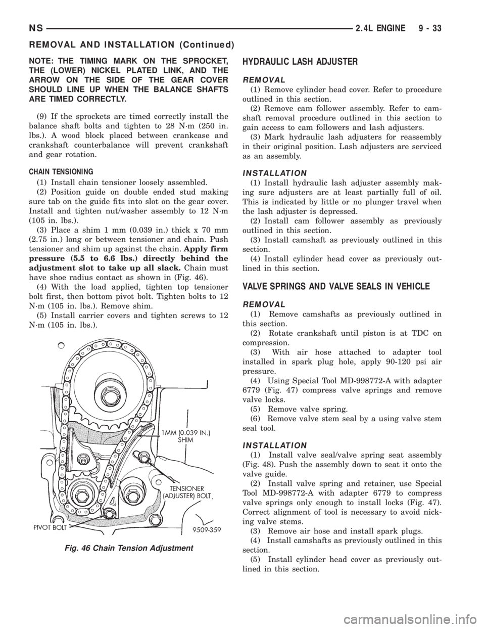
(3) Place a shim 1 mm (0.039 in.) thick x 70 mm
(2.75 in.) long or between tensioner and chain. Push
tensioner and shim up against the chain.Apply firm
pressure (5.5 to 6.6 lbs.) directly behind the
adjustment slot to take up all slack.Chain must
have shoe radius contact as shown in (Fig. 46).
(4) With the load applied, tighten top tensioner
bolt first, then bottom pivot bolt. Tighten bolts to 12
N´m (105 in. lbs.). Remove shim.
(5) Install carrier covers and tighten screws to 12
N´m (105 in. lbs.).HYDRAULIC LASH ADJUSTER
REMOVAL
(1) Remove cylinder head cover. Refer to procedure
outlined in this section.
(2) Remove cam follower assembly. Refer to cam-
shaft removal procedure outlined in this section to
gain access to cam followers and lash adjusters.
(3) Mark hydraulic lash adjusters for reassembly
in their original position. Lash adjusters are serviced
as an assembly.
INSTALLATION
(1) Install hydraulic lash adjuster assembly mak-
ing sure adjusters are at least partially full of oil.
This is indicated by little or no plunger travel when
the lash adjuster is depressed.
(2) Install cam follower assembly as previously
outlined in this section.
(3) Install camshaft as previously outlined in this
section.
(4) Install cylinder head cover as previously out-
lined in this section.
VALVE SPRINGS AND VALVE SEALS IN VEHICLE
REMOVAL
(1) Remove camshafts as previously outlined in
this section.
(2) Rotate crankshaft until piston is at TDC on
compression.
(3) With air hose attached to adapter tool
installed in spark plug hole, apply 90-120 psi air
pressure.
(4) Using Special Tool MD-998772-A with adapter
6779 (Fig. 47) compress valve springs and remove
valve locks.
(5) Remove valve spring.
(6) Remove valve stem seal by a using valve stem
seal tool.
INSTALLATION
(1) Install valve seal/valve spring seat assembly
(Fig. 48). Push the assembly down to seat it onto the
valve guide.
(2) Install valve spring and retainer, use Special
Tool MD-998772-A with adapter 6779 to compress
valve springs only enough to install locks (Fig. 47).
Correct alignment of tool is necessary to avoid nick-
ing valve stems.
(3) Remove air hose and install spark plugs.
(4) Install camshafts as previously outlined in this
section.
(5) Install cylinder head cover as previously out-
lined in this section.
Fig. 46 Chain Tension Adjustment
NS2.4L ENGINE 9 - 33
REMOVAL AND INSTALLATION (Continued)