1996 CHRYSLER VOYAGER run flat
[x] Cancel search: run flatPage 36 of 1938

CONDITION POSSIBLE CAUSES CORRECTION
Road Wander 1. Incorrect tire pressure 1. Inflate tires to recommended
pressure
2. Incorrect front or rear wheel toe 2. Check and reset wheel toe
3. Worn wheel bearings 3. Replace wheel bearing
4. Worn control arm bushings 4. Replace control arm bushing
5. Excessive friction in steering gear 5. Replace steering gear
6. Excessive friction in steering shaft
coupling6. Replace steering coupler
7. Excessive friction in strut upper
bearing7. Replace strut bearing
Lateral Pull 1. Unequal tire pressure 1. Inflate all tires to recommended
pressure
2. Radial tire lead 2. Perform lead correction procedure
3. Incorrect front wheel camber 3. Check and reset front wheel
camber
4. Power steering gear imbalance 4. Replace power steering gear
5. Wheel braking 5. Correct braking condition causing
lateral pull
Excessive Steering Free Play 1. Incorrect Steering Gear Adjustment 1. Adjust Or Replace Steering Gear
2. Worn or loose tie rod ends 2. Replace or tighten tie rod ends
3. Loose steering gear mounting bolts 3. Tighten steering gear bolts to
specified torque
4. Loose or worn steering shaft
coupler4. Replace steering shaft coupler
Excessive Steering Effort 1. Low tire pressure 1. Inflate all tires to recommended
pressure
2. Lack of lubricant in steering gear 2. Replace steering gear
3. Low power steering fluid level 3. Fill power steering fluid reservoir to
correct level
4. Loose power steering pump drive
belt4. Correctly adjust power steering
pump drive belt
5. Lack of lubricant in ball joints 5. Lubricate or replace ball joints
6. Steering gear malfunction 6. Replace steering gear
7. Lack of lubricant in steering
coupler7. Replace steering coupler
PRE-WHEEL ALIGNMENT INSPECTION
Before any attempt is made to change or correct
the wheel alignment factors. The following part
inspection and the necessary corrections should be
made to those parts which influence the steering of
the vehicle.
(1) Check and inflate all tires to recommended
pressure. All tires should be the same size and in
good condition and have approximately the same
wear. Note the type of tread wear which will aid in
diagnosing, see Wheels and Tires, Group 22.
(2) Check front wheel and tire assembly for radial
runout.
(3) Inspect lower ball joints and all steering link-
age for looseness.
(4) Check for broken or sagged front and rear
springs.(5) Check vehicle ride height to verify it is within
specifications.
(6) AlignmentMUSTonly be checked after the
vehicle has the following areas inspected and or
adjusted. Recommended tire pressures, full tank of
fuel, no passenger or luggage compartment load and
is on a level floor or a properly calibrated alignment
rack.
SERVICE PROCEDURES
WHEEL ALIGNMENT CHECK AND ADJUSTMENT
PROCEDURE
CASTER AND CAMBER
Front suspension Caster and Camber settings on
this vehicle are determined at the time the vehicle is
designed. This is done by determining the precise
2 - 4 SUSPENSIONNS
DIAGNOSIS AND TESTING (Continued)
Page 96 of 1938

ADJUSTER REAR DRUM BRAKE (AUTOMATIC)
The rear drum brakes on this vehicle automatically
adjust, when required, during the normal operation
of the vehicle every time the brakes are applied. Use
the following procedure to test the operation of the
automatic adjuster.
Place the vehicle on a hoist with a helper in the
driver's seat to apply the brakes. Remove the access
plug from the adjustment hole in each brake support
plate to provide visual access of the brake adjuster
star wheel.
Remove the park brake cable, for the wheel of the
vehicle that is being worked on, from the park brake
cable equalizer (Fig. 12). This is required to gain
access to the star wheel. If the cable is not removed
from the equalizer, the cable and spring inside of the
brake drum is in the way of the star wheel.
To eliminate the condition where maximum adjust-
ment of the rear brake shoes, does not allow the
automatic adjuster to operate when tested, back the
star wheel off approximately 30 notches. It will be
necessary to hold the adjuster lever away from the
star wheel to permit this adjustment.
Have the helper apply the brakes. Upon applica-
tion of the brake pedal, the adjuster lever lever
should move down, turning the adjuster star wheel.
Thus, a definite rotation of the adjuster star wheel
can be observed if the automatic adjuster is working
properly. If one or more adjusters do not function
properly, the respective drum must be removed for
adjuster servicing.
BRAKE ROTOR
Any servicing of the rotor requires extreme care to
maintain the rotor to within service tolerances to
ensure proper brake action.Before refinishing or refacing a rotor, the rotor
should be checked and inspected for the following
conditions:
Braking surface scoring, rust, impregnation of lin-
ing material and worn ridges.
Excessive rotor lateral runout or wobble.
Thickness variation in braking surface of the rotor
(Parallelism).
Dishing or distortion in braking surface of the
rotor (Flatness).
If a vehicle has not been driven for a period of
time, the rotors will rust in the area not covered by
the brake lining and cause noise and chatter when
the brakes are applied.
Excessive wear and scoring of the rotor can cause
temporary improper lining contact if ridges are not
removed from braking surface of rotor before instal-
lation of new brake shoe assemblies.
Some discoloration and/or wear of the rotor surface
is normal and does not require resurfacing when lin-
ings are replaced.
Excessive runout or wobble in a rotor can increase
pedal travel due to piston knock-back. This will also
increase guide pin bushing wear due to the tendency
of the caliper to follow rotor wobble.
Thickness variation in a rotor can also result in
pedal pulsation, chatter and surge due to variation in
brake output. This can also be caused by excessive
runout in the rotor and/or the hub.
Dishing or distortion can be caused by extreme
heat and abuse of the brakes.
CHECKING ROTOR FOR RUNOUT AND
THICKNESS
NOTE: The procedure for checking rotor runout
and thickness is the same for the front and rear
rotor. If there is a specification difference between
the front and rear rotor it will be designated as
such in the specifications of the following proce-
dure.
On-vehicle rotor runout is the combination of the
individual runout of the hub face and the runout of
the rotor. (The hub and rotor runouts are separable).
To measure runout on the vehicle, remove the wheel
and reinstall the lug nuts tightening the rotor to the
hub. Mount Dial Indicator, Special Tool C-3339 with
Mounting Adaptor, Special Tool SP- 1910 on steering
arm. Dial indicator plunger should contact braking
surface of rotor approximately 10 mm (0.393 in.)
from outer edge of rotor (Fig. 13). Check lateral
runout on both sides of rotor. Lateral runout of the
rotor should not exceed 0.13 mm (0.005 inch).
If lateral runout is in excess of the specification,
check the lateral runout of the hub face. Before
removing rotor from hub, make a chalk mark across
Fig. 12 Park Brake Cable Equlizer
5 - 14 BRAKESNS
DIAGNOSIS AND TESTING (Continued)
Page 212 of 1938

friction area should be slightly concave, with the
inner diameter 0.02 mm to 0.1 mm (.0008 in. to .0039
in.) below the outer diameter. It should also be free
from discoloration, burned areas, cracks, grooves, or
ridges.
Using a surface plate, test cover for flatness. All
sections around attaching bolt holes should be in con-
tact with surface plate within .015 inch.
The cover should be a snug fit on flywheel dowels.
If the clutch assembly does not meet these require-
ments, it should be replaced.
INSTALLATION
(1) Position the clutch and pressure plate onto the
flywheel.
(2) Insert the universal clutch alignment tool into
the clutch disc.
(3) To avoid distortion of the pressure plate, bolts
should be tightened a few turns at a time (Fig. 19).
Use a crisscross pattern until all bolts are seated.
Tighten pressure plate bolts to 27 N´m (20 ft. lbs.).
(4) Remove the universal clutch alignment tool.
(5) Install the transaxle, refer to Group 21, Tran-
saxle.
(6) Fill transaxle to the proper level with the spec-
ified lubricant.
(7) While the vehicle is elevated slightly, run the
transaxle through all the forward gears. Apply
brakes and shift into reverse. Run the transaxle
through reverse gear.
(8) Check the transaxle for leaks and recheck the
level of the transaxle lubricant.
CLUTCH RELEASE BEARING AND FORK
Remove the transaxle from the vehicle. See Group
21, for removal and installation procedures.
REMOVAL
(1) Remove clutch release shaft E-clip (Fig. 20).
(2) Remove the clutch release shaft and then slide
the fork and bearing assembly off the bearing pilot
(Fig. 21).
Fig. 19 2.5 Diesel Clutch Assembly
Fig. 20 E-clip at Clutch Release Lever Shaft
Fig. 21 Clutch Release Shaft
6 - 14 CLUTCHNS/GS
REMOVAL AND INSTALLATION (Continued)
Page 499 of 1938

SERVICE PROCEDURES
CLEANUP PROCEDURE
Roll or fold the passenger airbag towards the
instrument panel surface and close the door over the
folded bag. Then tape the door shut.
Use a vacuum cleaner to remove any residual pow-
der from the vehicle interior. Work from the outside
in to avoid kneeling or sitting in a contaminated
area. Vacuum the heater and A/C outlets as well (Fig.
2). If HVAC was in RECIRC mode at time of airbag
deployment, operate HVAC blower on low speed/heat
and vacuum powder residue expelled from the heat
outlets. Multiple vacuum cleaning may to necessary
to decontaminate the interior of the vehicle.
NOTE: Dispose deployed airbag properly, contact
dealer or government agency for disposal recom-
mendations.
SERVICE OF DEPLOYED AIRBAG MODULE
DRIVER AIRBAG
If a Driver Airbag Module has been deployed, but
not due to a collision, replace the following:
²Driver Airbag Module
²Clockspring assembly
²Driver airbag cover/horn switch
The components above must be replaced because
they cannot be reused. Replace any other driver air-
bag system components if damaged.
PASSENGER AIRBAG
If a Passenger Airbag Module has been deployed,
but not due to a collision, replace the following:
²Passenger Airbag Module
²Upper instrument panel with pad
The component above must be replaced because
they cannot be reused. Inspect the heat duct near the
passenger airbag for any damage replace as neces-sary. Replace any other passenger airbag system
components if damaged.
HANDLING AIRBAG MODULE
DEPLOYED MODULE
The vehicle interior may contain a very small
amount of sodium hydroxide powder, a by-product of
airbag deployment. Sodium hydroxide powder can
irritate the skin, eyes, nose and throat. Wear safety
glasses, rubber gloves, and long sleeved clothing
when cleaning any of the powder residue from the
vehicle.
If you find that the cleanup is irritating your skin,
run cool water over the affected area. Also, if you
experience nasal or throat irritation, exit the vehicle
for fresh air until the irritation ceases. If irritation
continues, see a physician.
UNDEPLOYED
The airbag modules must be stored in its original
special container until used for service. At no time
should a source of electricity be permitted near the
inflator on the back of an airbag module. When car-
rying or handling an undeployed airbag module, the
trim side of the airbag should be pointing away from
the body to minimize possibility of injury if acciden-
tal deployment occurs. Do not place undeployed air-
bag face down on a solid surface, the airbag will
propel into the air if accidentally deployment occurs.
REMOVAL AND INSTALLATION
AIRBAG CONTROL MODULE
WARNING: THE ACM CONTAINS THE IMPACT
SENSOR WHICH ENABLES THE SYSTEM TO
DEPLOY THE AIRBAGS. TO AVOID ACCIDENTAL
DEPLOYMENT, NEVER CONNECT ACM ELECTRI-
CALLY TO THE SYSTEM WHILE VEHICLE BATTERY
IS CONNECTED. DISCONNECT AND ISOLATE THE
BATTERY NEGATIVE CABLE BEFORE BEGINNING
ANY AIRBAG SYSTEM COMPONENT SERVICE PRO-
CEDURES. THIS WILL DISABLE THE AIRBAG SYS-
TEM. FAILURE TO DISCONNECT THE BATTERY
COULD RESULT IN ACCIDENTAL AIRBAG DEPLOY-
MENT AND POSSIBLE PERSONAL INJURY. ALLOW
SYSTEM CAPACITOR TO DISCHARGE FOR TWO
MINUTES BEFORE REMOVING AIRBAG COMPO-
NENTS.
REMOVAL
(1) Disconnect and isolate battery negative cable.
Allow at least two minutes for the reserve capacitor
in the Airbag Control Module (ACM) to discharge.
Fig. 2 Vacuum Heater and A/C Outlets
NSRESTRAINT SYSTEM 8M - 3
Page 1106 of 1938

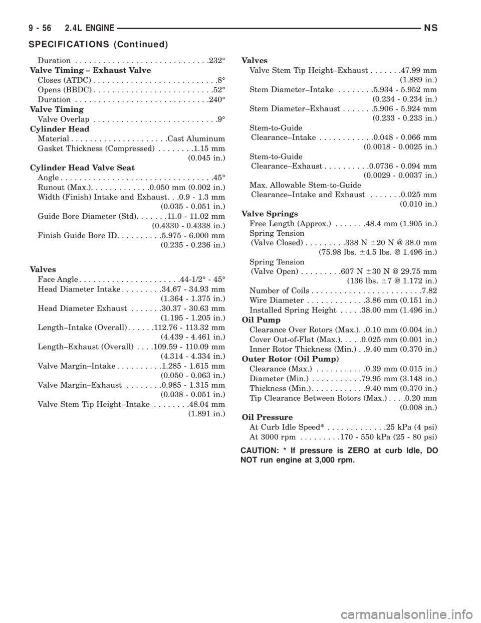
Duration.............................232É
Valve Timing ± Exhaust Valve
Closes (ATDC)...........................8É
Opens (BBDC)..........................52É
Duration.............................240É
Valve Timing
Valve Overlap...........................9É
Cylinder Head
Material.....................Cast Aluminum
Gasket Thickness (Compressed)........1.15 mm
(0.045 in.)
Cylinder Head Valve Seat
Angle.................................45É
Runout (Max.).............0.050 mm (0.002 in.)
Width (Finish) Intake and Exhaust. . .0.9 - 1.3 mm
(0.035 - 0.051 in.)
Guide Bore Diameter (Std).......11.0-11.02 mm
(0.4330 - 0.4338 in.)
Finish Guide Bore ID..........5.975 - 6.000 mm
(0.235 - 0.236 in.)
Valves
Face Angle......................44-1/2É - 45É
Head Diameter Intake.........34.67 - 34.93 mm
(1.364 - 1.375 in.)
Head Diameter Exhaust.......30.37 - 30.63 mm
(1.195 - 1.205 in.)
Length±Intake (Overall)......112.76 - 113.32 mm
(4.439 - 4.461 in.)
Length±Exhaust (Overall). . . .109.59 - 110.09 mm
(4.314 - 4.334 in.)
Valve Margin±Intake..........1.285 - 1.615 mm
(0.050 - 0.063 in.)
Valve Margin±Exhaust........0.985 - 1.315 mm
(0.038 - 0.051 in.)
Valve Stem Tip Height±Intake........48.04 mm
(1.891 in.)Valves
Valve Stem Tip Height±Exhaust.......47.99 mm
(1.889 in.)
Stem Diameter±Intake........5.934 - 5.952 mm
(0.234 - 0.234 in.)
Stem Diameter±Exhaust.......5.906 - 5.924 mm
(0.233 - 0.233 in.)
Stem-to-Guide
Clearance±Intake............0.048 - 0.066 mm
(0.0018 - 0.0025 in.)
Stem-to-Guide
Clearance±Exhaust..........0.0736 - 0.094 mm
(0.0029 - 0.0037 in.)
Max. Allowable Stem-to-Guide
Clearance±Intake and Exhaust.......0.025 mm
(0.010 in.)
Valve Springs
Free Length (Approx.).......48.4 mm (1.905 in.)
Spring Tension
(Valve Closed).........338 N620 N @ 38.0 mm
(75.98 lbs.64.5 lbs. @ 1.496 in.)
Spring Tension
(Valve Open).........607 N630 N @ 29.75 mm
(136 lbs.67 @ 1.172 in.)
Number of Coils........................7.82
Wire Diameter.............3.86 mm (0.151 in.)
Installed Spring Height.....38.00 mm (1.496 in.)
Oil Pump
Clearance Over Rotors (Max.). .0.10 mm (0.004 in.)
Cover Out-of-Flat (Max.).....0.025 mm (0.001 in.)
Inner Rotor Thickness (Min.) . .9.40 mm (0.370 in.)
Outer Rotor (Oil Pump)
Clearance (Max.)...........0.39 mm (0.015 in.)
Diameter (Min.)...........79.95 mm (3.148 in.)
Thickness (Min.)............9.40 mm (0.370 in.)
Tip Clearance Between Rotors (Max.). . . .0.20 mm
(0.008 in.)
Oil Pressure
At Curb Idle Speed*.............25kPa(4psi)
At 3000 rpm.........170 - 550 kPa (25 - 80 psi)
CAUTION: * If pressure is ZERO at curb Idle, DO
NOT run engine at 3,000 rpm.
9 - 56 2.4L ENGINENS
SPECIFICATIONS (Continued)
Page 1140 of 1938

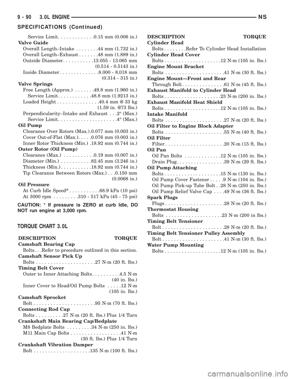
Service Limit.............0.15 mm (0.006 in.)
Valve Guide
Overall Length±Intake........44mm(1.732 in.)
Overall Length±Exhaust.......48mm(1.889 in.)
Outside Diameter...........13.055 - 13.065 mm
(0.514 - 0.5143 in.)
Inside Diameter..............8.000 - 8.018 mm
(0.314 - 315 in.)
Valve Springs
Free Length (Approx.).......49.8 mm (1.960 in.)
Service Limit............48.8 mm (1.9213 in.)
Loaded Height...............40.4 mm @ 33 kg
(1.59 in. @73 lbs.)
Perpendicularity±Intake and Exhaust . . .2É (Max.)
Service Limit.....................4É(Max.)
Oil Pump
Clearance Over Rotors (Max.) .0.077 mm (0.003 in.)
Cover Out-of-Flat (Max.).....0.076 mm (0.003 in.)
Inner Rotor Thickness (Min.) .18.92 mm (0.744 in.)
Outer Rotor (Oil Pump)
Clearance (Max.)...........0.19 mm (0.007 in.)
Diameter (Min.)...........82.45 mm (3.246 in.)
Thickness (Min.)...........18.92 mm (0.744 in.)
Tip Clearance Between Rotors (Max.) . . .0.150 mm
(0.0068 in.)
Oil Pressure
At Curb Idle Speed*...........68.9 kPa (10 psi)
At 3000 rpm.........310 - 517 kPa (45 - 75 psi)
CAUTION: * If pressure is ZERO at curb Idle, DO
NOT run engine at 3,000 rpm.
TORQUE CHART 3.0L
DESCRIPTION TORQUE
Camshaft Bearing Cap
Bolts. . .Refer to procedure outlined in this section.
Camshaft Sensor Pick Up
Bolts.....................27N´m(20ft.lbs.)
Timing Belt Cover
Outer to Inner Attaching Bolts..........4.5 N´m
(40 in. lbs.)
Inner Cover to Head/Oil Pump Bolts.....12N´m
(105 in. lbs.)
Camshaft Sprocket
Bolt......................95N´m(70ft.lbs.)
Connecting Rod Cap
Bolts..........27N´m(20ft.lbs.) Plus 1/4 Turn
Crankshaft Main Bearing Cap/Bedplate
M8 Bedplate Bolts.........34N´m(250 in. lbs.)
M11 Main Cap Bolts..................41N´m
(30 ft. lbs.) Plus 1/4 Turn
Crankshaft Vibration Damper
Bolt....................135 N´m (100 ft. lbs.)DESCRIPTION TORQUE
Cylinder Head
Bolts........Refer To Cylinder Head Installation
Cylinder Head Cover
Bolts....................12N´m(105 in. lbs.)
Engine Mount Bracket
Bolts.....................41N´m(30ft.lbs.)
Engine MountÐFront and Rear
Through Bolt...............61N´m(45ft.lbs.)
Exhaust Manifold to Cylinder Head
Bolts....................23N´m(200 in. lbs.)
Exhaust Manifold Heat Shield
Bolts....................12N´m(105 in. lbs.)
Intake Manifold
Bolts.....................27N´m(20ft.lbs.)
Oil Filter to Engine Block Adapter
Bolts.....................55N´m(40ft.lbs.)
Oil Filter
Filter.....................20N´m(15ft.lbs.)
Oil Pan
Oil Pan Bolts.............12N´m(105 in. lbs.)
Drain Plug.................39N´m(29ft.lbs.)
Oil Pump Attaching
Bolts....................15N´m(130 in. lbs.)
Oil Pump Cover Fastener.....9N´m(104 in. lbs.)
Oil Pump Pick-up Tube Bolt . .28 N´m (250 in. lbs.)
Oil Pump Relief Valve Cap. . . .49 N´m (36 ft. lbs.)
Spark Plugs
Plugs.....................28N´m(20ft.lbs.)
Thermostat Housing
Bolts....................23N´m(200 in lbs.)
Timing Belt Tensioner
Bolt......................28N´m(20ft.lbs.)
Timing Belt Tensioner Pulley Assembly
Bolt......................41N´m(30ft.lbs.)
Water Pump Mounting
Bolts....................12N´m(105 in. lbs.)
9 - 90 3.0L ENGINENS
SPECIFICATIONS (Continued)
Page 1144 of 1938

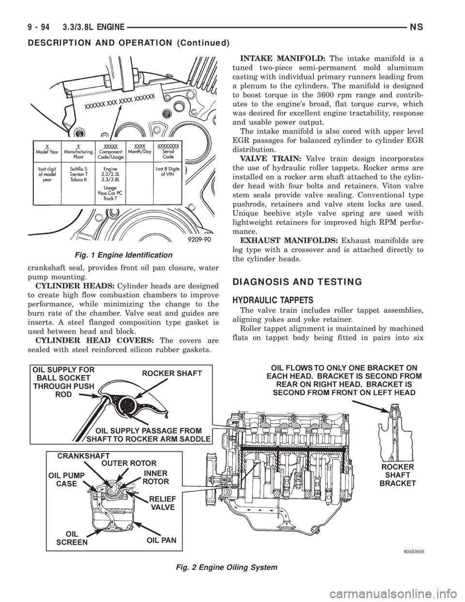
crankshaft seal, provides front oil pan closure, water
pump mounting.
CYLINDER HEADS:Cylinder heads are designed
to create high flow combustion chambers to improve
performance, while minimizing the change to the
burn rate of the chamber. Valve seat and guides are
inserts. A steel flanged composition type gasket is
used between head and block.
CYLINDER HEAD COVERS:The covers are
sealed with steel reinforced silicon rubber gaskets.INTAKE MANIFOLD:The intake manifold is a
tuned two-piece semi-permanent mold aluminum
casting with individual primary runners leading from
a plenum to the cylinders. The manifold is designed
to boost torque in the 3600 rpm range and contrib-
utes to the engine's broad, flat torque curve, which
was desired for excellent engine tractability, response
and usable power output.
The intake manifold is also cored with upper level
EGR passages for balanced cylinder to cylinder EGR
distribution.
VALVE TRAIN:Valve train design incorporates
the use of hydraulic roller tappets. Rocker arms are
installed on a rocker arm shaft attached to the cylin-
der head with four bolts and retainers. Viton valve
stem seals provide valve sealing. Conventional type
pushrods, retainers and valve stem locks are used.
Unique beehive style valve spring are used with
lightweight retainers for improved high RPM perfor-
mance.
EXHAUST MANIFOLDS:Exhaust manifolds are
log type with a crossover and is attached directly to
the cylinder heads.
DIAGNOSIS AND TESTING
HYDRAULIC TAPPETS
The valve train includes roller tappet assemblies,
aligning yokes and yoke retainer.
Roller tappet alignment is maintained by machined
flats on tappet body being fitted in pairs into six
Fig. 2 Engine Oiling System
Fig. 1 Engine Identification
9 - 94 3.3/3.8L ENGINENS
DESCRIPTION AND OPERATION (Continued)
Page 1175 of 1938

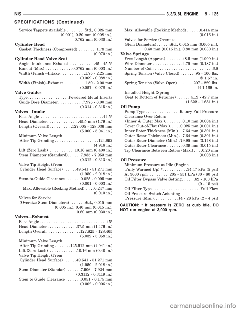
Service Tappets Available........Std., 0.025 mm
(0.001), 0.20 mm (0.008 in.),
0.762 mm (0.030 in.)
Cylinder Head
Gasket Thickness (Compressed)........1.78 mm
(0.070 in.)
Cylinder Head Valve Seat
Angle±Intake and Exhaust...........45-45.5É
Runout (Max)............0.0762 mm (0.003 in.)
Width (Finish)±Intake...........1.75 - 2.25 mm
(0.069 - 0.088 in.)
Width (Finish)±Exhaust.........1.50 - 2.00 mm
(0.057 - 0.078 in.)
Valve Guides
Type..................Powdered Metal Inserts
Guide Bore Diameter...........7.975 - 8.00 mm
(0.314 - 0.315 in.)
ValvesÐIntake
Face Angle...........................44.5É
Head Diameter..............45.5 mm (1.79 in.)
Length (Overall)..........127.005 - 128.036 mm
(5.000 - 5.041 in.)
Minimum Valve Length
After Tip Grinding...................124.892
(4.916 in.)
Lift (Zero Lash)...........10.16 mm (0.400 in.)
Stem Diameter (Standard)......7.935 - 7.953 mm
(0.312 - 0.313 in.)
Valve Tip Height (From
Cylinder Head Surface)......49.541 - 51.271 mm
(1.950 - 2.018 in.)
Stem-to-Guide Clearance.......0.025 - 0.095 mm
(0.001 - 0.003 in.)
Max. Allowable (Rocking Method). . . .0.247 mm
(0.010 in.)
Valves for Service
(Oversize Stem Diameters).......Std., 0.015 mm
(0.005 in.), 0.40 mm (0.015 in.),
0.80 mm (0.030 in.)
ValvesÐExhaust
Face Angle.............................45É
Head Diameter.............37.5 mm (1.476 in.)
Length Overall..............127.825 - 128.465
(5.032 - 5.058 in.)
Minimum Valve Length
After Tip Grinding.......125.512 mm (4.941 in.)
Lift (Zero Lash)............10.16 mm (0.40 in.)
Valve Tip Height (From
Cylinder Head Surface)......49.541 - 51.271 mm
(1.950 - 2.018 in.)
Stem Diameter (Standar).......7.906 - 7.924 mm
(0.3112 - 0.3119 in.)
Stem to Guide Clearance.......0.051 - 0.175 mm
(0.002 - 0.006 in.)Max. Allowable (Rocking Method)......0.414 mm
(0.016 in.)
Valves for Service (Oversize
Stem Diameters)......Std., 0.015 mm (0.005 in.),
0.40 mm (0.015 in.), 0.80 mm (0.030 in.)
Valve Springs
Free Length (Approx.).......48.5 mm (1.909 in.)
Wire Diameter.............4.75 mm (0.187 in.)
Number of Coils.........................6.8
Spring Tension (Valve Closed).......95-100lbs.
@ 1.57 in.
Spring Tension (Valve Open).......207 - 229 lbs.
@ 1.169 in.
Installed Height (Spring
Seat to Bottom of Retainer)......41.2 - 42.7 mm
(1.622 - 1.681 in.)
Oil Pump
Pump Type...............Rotary Full Pressure
Clearance Over Rotors
(Inner & Outer Max.)........0.10 mm (0.004 in.)
Cover Out-of-Flat (Max.).....0.025 mm (0.001 in.)
Inner Rotor Thickness (Min.) . .7.64 mm (0.301 in.)
Outer Rotor Thickness (Min.) . .7.64 mm (0.301 in.)
Outer Rotor Diameter (Min.) .79.95 mm (3.148 in.)
Outer Rotor Clearance.......0.39 mm (0.015 in.)
Tip Clearance Between Rotors (Max.). . . .0.20 mm
(0.008 in.)
Oil Pressure
Minimum Pressure at Idle (Engine
Fully Warmed Up)*...........34.47 kPa (5 psi)
At 3000 rpm.........205 - 551 kPa (30 - 80 psi)
Oil Filter Bypass Valve Setting......62-103kPa
(9 - 15 psi)
Oil Filter Type.....................Full Flow
Oil Pressure Switch Actuating
Pressure (Min.)...........14-28kPa(2 - 4 psi)
CAUTION: * If pressure is ZERO at curb Idle, DO
NOT run engine at 3,000 rpm.
NS3.3/3.8L ENGINE 9 - 125
SPECIFICATIONS (Continued)