1996 CHRYSLER VOYAGER run flat
[x] Cancel search: run flatPage 1265 of 1938
CAUTION: When servicing, care must be exercised
not to dent or bend the bellows of the flex-joint.
Should this occur, the flex-joint will eventually fail
and require the catalytic converter be replaced.
DESCRIPTION AND OPERATION
INTAKE/EXHAUST MANIFOLDÐ2.4L ENGINE
The intake manifold is a tuned two-piece alumi-
num casting with individual primary runners leading
from a plenum to the cylinders. The manifold is
designed to boost torque which is desired for excel-
lent engine response and usable power output.
The exhaust manifold is made of nodular cast iron
for strength and high temperatures.
INTAKE/EXHAUST MANIFOLDÐ3.0L ENGINE
The aluminum alloy manifold is a cross type with
long runners to improve air flow. The runners,
attaching below at the cylinder head, also attach
above and support an air plenum. The air plenum
chamber absorbs air pulsations created during the
suction phase of each cylinder.Both exhaust manifolds are a log style made of
ductile cast iron. Exhaust gasses, collected from the
front cylinder bank, leave the front manifold through
an end outlet and are fed through an upper crossover
tube to the rear manifold. The collected exhaust from
both manifolds are combined at the exhaust outlet, to
the exhaust pipe.
INTAKE/EXHAUST MANIFOLDÐ3.3/3.8L ENGINES
The intake manifold is a tuned two-piece semi-per-
manent mold aluminum casting with individual pri-
mary runners leading from a plenum to the
cylinders. The manifold is designed to boost torque in
the 3600 rpm range and contributes to the engine's
broad, flat torque curve, which was desired for excel-
lent engine tractability, response and usable power
output.
The intake manifold is also cored with upper level
EGR passages for balanced cylinder to cylinder EGR
distribution.
The exhaust manifolds are log type with a cross-
over and are attached directly to the cylinder heads.
They are made from nodular cast iron.
DIAGNOSIS AND TESTING
EXHAUST SYSTEM
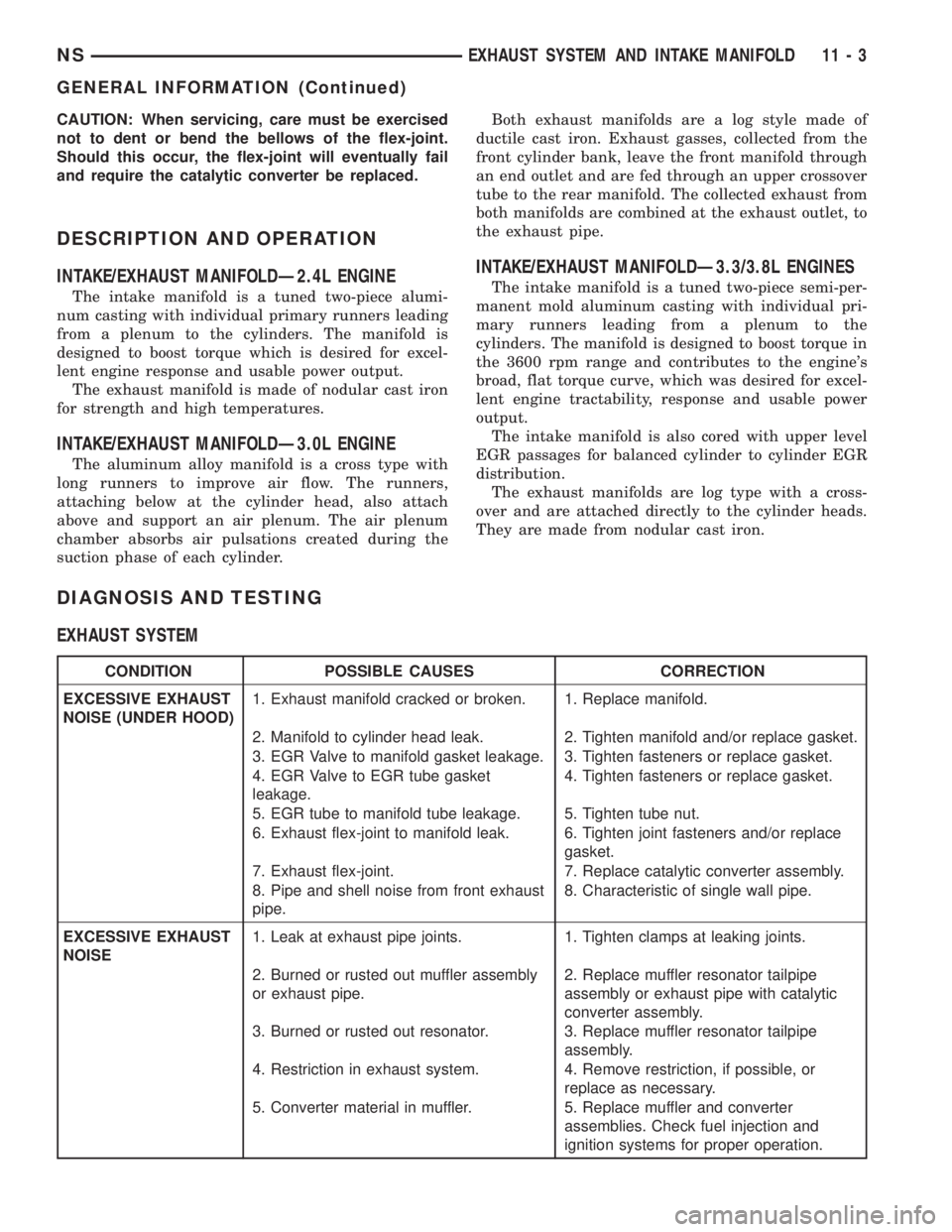
CONDITION POSSIBLE CAUSES CORRECTION
EXCESSIVE EXHAUST
NOISE (UNDER HOOD)1. Exhaust manifold cracked or broken. 1. Replace manifold.
2. Manifold to cylinder head leak. 2. Tighten manifold and/or replace gasket.
3. EGR Valve to manifold gasket leakage. 3. Tighten fasteners or replace gasket.
4. EGR Valve to EGR tube gasket
leakage.4. Tighten fasteners or replace gasket.
5. EGR tube to manifold tube leakage. 5. Tighten tube nut.
6. Exhaust flex-joint to manifold leak. 6. Tighten joint fasteners and/or replace
gasket.
7. Exhaust flex-joint. 7. Replace catalytic converter assembly.
8. Pipe and shell noise from front exhaust
pipe.8. Characteristic of single wall pipe.
EXCESSIVE EXHAUST
NOISE1. Leak at exhaust pipe joints. 1. Tighten clamps at leaking joints.
2. Burned or rusted out muffler assembly
or exhaust pipe.2. Replace muffler resonator tailpipe
assembly or exhaust pipe with catalytic
converter assembly.
3. Burned or rusted out resonator. 3. Replace muffler resonator tailpipe
assembly.
4. Restriction in exhaust system. 4. Remove restriction, if possible, or
replace as necessary.
5. Converter material in muffler. 5. Replace muffler and converter
assemblies. Check fuel injection and
ignition systems for proper operation.
NSEXHAUST SYSTEM AND INTAKE MANIFOLD 11 - 3
GENERAL INFORMATION (Continued)
Page 1430 of 1938
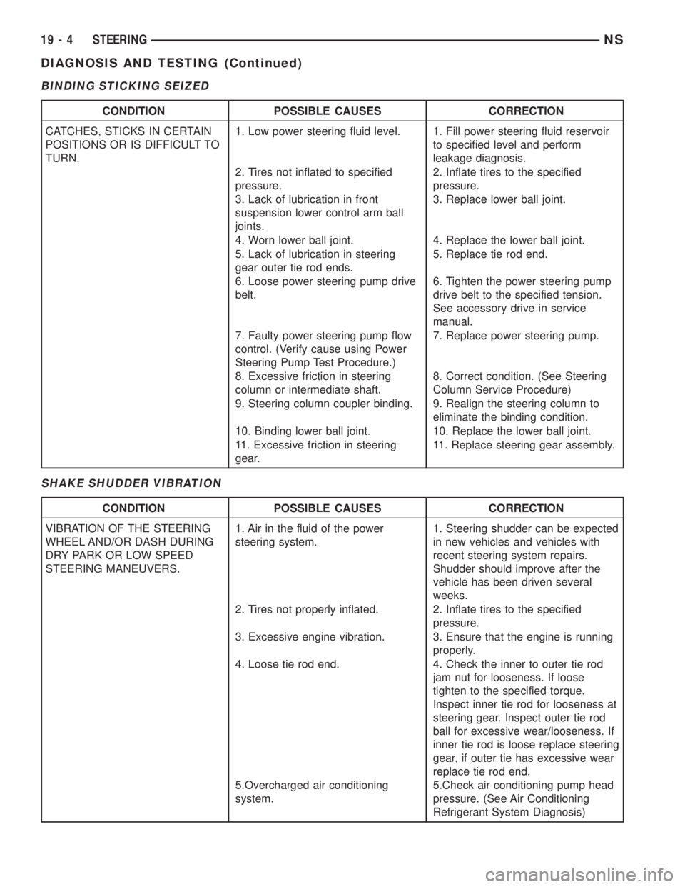
BINDING STICKING SEIZED
SHAKE SHUDDER VIBRATION
CONDITION POSSIBLE CAUSES CORRECTION
CATCHES, STICKS IN CERTAIN
POSITIONS OR IS DIFFICULT TO
TURN.1. Low power steering fluid level. 1. Fill power steering fluid reservoir
to specified level and perform
leakage diagnosis.
2. Tires not inflated to specified
pressure.2. Inflate tires to the specified
pressure.
3. Lack of lubrication in front
suspension lower control arm ball
joints.3. Replace lower ball joint.
4. Worn lower ball joint. 4. Replace the lower ball joint.
5. Lack of lubrication in steering
gear outer tie rod ends.5. Replace tie rod end.
6. Loose power steering pump drive
belt.6. Tighten the power steering pump
drive belt to the specified tension.
See accessory drive in service
manual.
7. Faulty power steering pump flow
control. (Verify cause using Power
Steering Pump Test Procedure.)7. Replace power steering pump.
8. Excessive friction in steering
column or intermediate shaft.8. Correct condition. (See Steering
Column Service Procedure)
9. Steering column coupler binding. 9. Realign the steering column to
eliminate the binding condition.
10. Binding lower ball joint. 10. Replace the lower ball joint.
11. Excessive friction in steering
gear.11. Replace steering gear assembly.
CONDITION POSSIBLE CAUSES CORRECTION
VIBRATION OF THE STEERING
WHEEL AND/OR DASH DURING
DRY PARK OR LOW SPEED
STEERING MANEUVERS.1. Air in the fluid of the power
steering system.1. Steering shudder can be expected
in new vehicles and vehicles with
recent steering system repairs.
Shudder should improve after the
vehicle has been driven several
weeks.
2. Tires not properly inflated. 2. Inflate tires to the specified
pressure.
3. Excessive engine vibration. 3. Ensure that the engine is running
properly.
4. Loose tie rod end. 4. Check the inner to outer tie rod
jam nut for looseness. If loose
tighten to the specified torque.
Inspect inner tie rod for looseness at
steering gear. Inspect outer tie rod
ball for excessive wear/looseness. If
inner tie rod is loose replace steering
gear, if outer tie has excessive wear
replace tie rod end.
5.Overcharged air conditioning
system.5.Check air conditioning pump head
pressure. (See Air Conditioning
Refrigerant System Diagnosis)
19 - 4 STEERINGNS
DIAGNOSIS AND TESTING (Continued)
Page 1722 of 1938

TIRE WEAR PATTERNS
Under inflation will cause wear on the shoulders of
tire. Over inflation will cause wear at the center of
tire.
Excessive camber causes the tire to run at an
angle to the road. One side of tread is then worn
more than the other (Fig. 5).
Excessive toe-in or toe-out causes wear on the
tread edges and a feathered effect across the tread
(Fig. 5).
TIRE NOISE OR VIBRATION
Radial-ply tires are sensitive to force impulses
caused by improper mounting, vibration, wheel
defects, or possibly tire imbalance.To find out if tires are causing the noise or vibra-
tion, drive the vehicle over a smooth road at varying
speeds. Note the noise level during acceleration and
deceleration. The engine, differential and exhaust
noises will change as speed varies, while the tire
noise will usually remain constant.
LEAD CORRECTION CHART
Use the following chart to correct a vehicle leading
or drifting problem.
Fig. 5 Tire Wear Patterns
22 - 4 TIRES AND WHEELSNS
DIAGNOSIS AND TESTING (Continued)
Page 1724 of 1938
SERVICE PROCEDURES
TIRE AND WHEEL ROTATION (NON-DIRECTIONAL
THREAD PATTERN)
Tires on the front and rear axles operate at differ-
ent loads and perform different functions. For these
reasons, they wear at unequal rates, and tend to
develop irregular wear patterns. These effects can be
reduced by timely rotation of tires. The benefits of
rotation are especially worthwhile. Rotation will
increase tread life, help to maintain mud, snow, and
wet traction levels, and contribute to a smooth, quiet
ride.
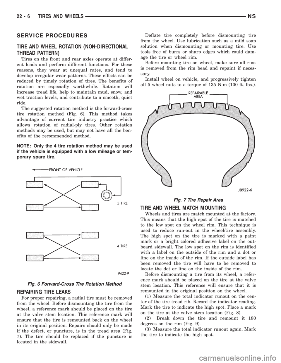
The suggested rotation method is the forward-cross
tire rotation method (Fig. 6). This method takes
advantage of current tire industry practice which
allows rotation of radial-ply tires. Other rotation
methods may be used, but may not have all the ben-
efits of the recommended method.
NOTE: Only the 4 tire rotation method may be used
if the vehicle is equipped with a low mileage or tem-
porary spare tire.
REPAIRING TIRE LEAKS
For proper repairing, a radial tire must be removed
from the wheel. Before dismounting the tire from the
wheel, a reference mark should be placed on the tire
at the valve stem location. This reference mark will
ensure that the tire is remounted back on the wheel
in its original position. Repairs should only be made
if the defect, or puncture, is in the tread area (Fig.
7). The tire should be replaced if the puncture is
located in the sidewall.Deflate tire completely before dismounting tire
from the wheel. Use lubrication such as a mild soap
solution when dismounting or mounting tire. Use
tools free of burrs or sharp edges which could dam-
age the tire or wheel rim.
Before mounting tire on wheel, make sure all rust
is removed from the rim bead and repaint if neces-
sary.
Install wheel on vehicle, and progressively tighten
all 5 wheel nuts to a torque of 135 N´m (100 ft. lbs.).
TIRE AND WHEEL MATCH MOUNTING
Wheels and tires are match mounted at the factory.
This means that the high spot of the tire is matched
to the low spot on the wheel rim. This technique is
used to reduce run-out in the wheel/tire assembly.
The high spot on the tire is marked with a paint
mark or a bright colored adhesive label on the out-
board sidewall. The low spot on the rim is identified
with a label on the outside of the rim and a dot or
line on the inside of the rim. If the outside label has
been removed the tire will have to be removed to
locate the dot or line on the inside of the rim.
Before dismounting a tire from its wheel, a refer-
ence mark should be placed on the tire at the valve
stem location. This reference will ensure that it is
remounted in the original position on the wheel.
(1) Measure the total indicator runout on the cen-
ter of the tire tread rib. Record the indicator reading.
Mark the tire to indicate the high spot. Place a mark
on the tire at the valve stem location (Fig. 8).
(2) Break down the tire and remount it 180
degrees on the rim (Fig. 9).
(3) Measure the total indicator runout again. Mark
the tire to indicate the high spot.
Fig. 6 Forward-Cross Tire Rotation Method
Fig. 7 Tire Repair Area
22 - 6 TIRES AND WHEELSNS
Page 1727 of 1938
WHEELS
INDEX
page page
DESCRIPTION AND OPERATION
WHEEL INFORMATION.................... 9
DIAGNOSIS AND TESTING
TIRE AND WHEEL RUNOUT............... 10
WHEEL INSPECTION...................... 9SERVICE PROCEDURES
TIRE AND WHEEL BALANCE............... 11
WHEEL INSTALLATION................... 11
SPECIFICATIONS
WHEEL SPECIFICATIONS................. 12
DESCRIPTION AND OPERATION
WHEEL INFORMATION
Original equipment wheels are designed for proper
operation at all loads up to the specified maximum
vehicle capacity.
All models use steel or aluminum drop center
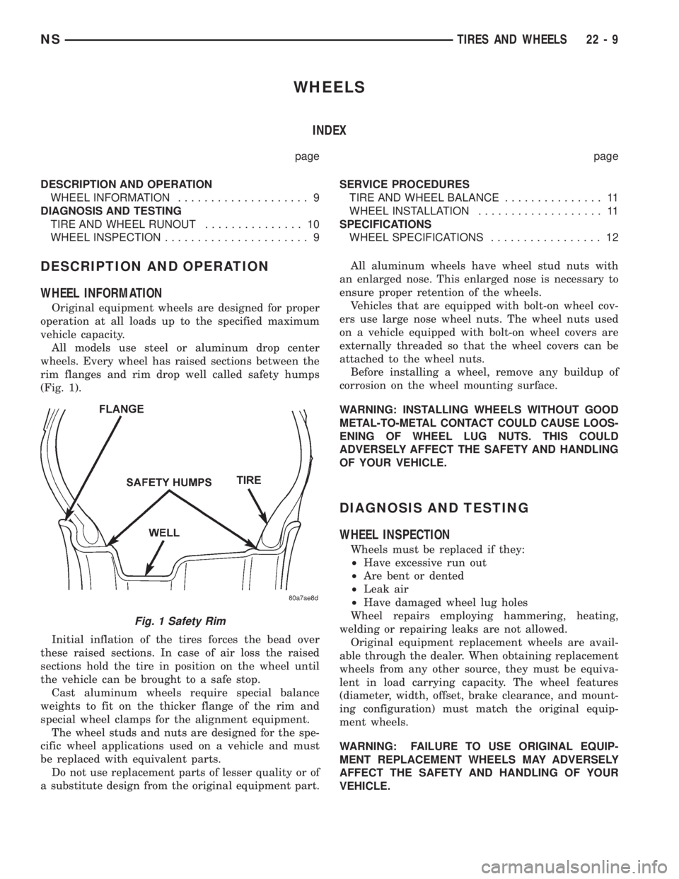
wheels. Every wheel has raised sections between the
rim flanges and rim drop well called safety humps
(Fig. 1).
Initial inflation of the tires forces the bead over
these raised sections. In case of air loss the raised
sections hold the tire in position on the wheel until
the vehicle can be brought to a safe stop.
Cast aluminum wheels require special balance
weights to fit on the thicker flange of the rim and
special wheel clamps for the alignment equipment.
The wheel studs and nuts are designed for the spe-
cific wheel applications used on a vehicle and must
be replaced with equivalent parts.
Do not use replacement parts of lesser quality or of
a substitute design from the original equipment part.All aluminum wheels have wheel stud nuts with
an enlarged nose. This enlarged nose is necessary to
ensure proper retention of the wheels.
Vehicles that are equipped with bolt-on wheel cov-
ers use large nose wheel nuts. The wheel nuts used
on a vehicle equipped with bolt-on wheel covers are
externally threaded so that the wheel covers can be
attached to the wheel nuts.
Before installing a wheel, remove any buildup of
corrosion on the wheel mounting surface.
WARNING: INSTALLING WHEELS WITHOUT GOOD
METAL-TO-METAL CONTACT COULD CAUSE LOOS-
ENING OF WHEEL LUG NUTS. THIS COULD
ADVERSELY AFFECT THE SAFETY AND HANDLING
OF YOUR VEHICLE.
DIAGNOSIS AND TESTING
WHEEL INSPECTION
Wheels must be replaced if they:
²Have excessive run out
²Are bent or dented
²Leak air
²Have damaged wheel lug holes
Wheel repairs employing hammering, heating,
welding or repairing leaks are not allowed.
Original equipment replacement wheels are avail-
able through the dealer. When obtaining replacement
wheels from any other source, they must be equiva-
lent in load carrying capacity. The wheel features
(diameter, width, offset, brake clearance, and mount-
ing configuration) must match the original equip-
ment wheels.
WARNING: FAILURE TO USE ORIGINAL EQUIP-
MENT REPLACEMENT WHEELS MAY ADVERSELY
AFFECT THE SAFETY AND HANDLING OF YOUR
VEHICLE.
Fig. 1 Safety Rim
NSTIRES AND WHEELS 22 - 9
Page 1728 of 1938
WARNING: REPLACEMENT WITH USED WHEELS
IS NOT RECOMMENDED. THE SERVICE HISTORY
OF THE RIM MAY HAVE INCLUDED SEVERE TREAT-
MENT OR VERY HIGH MILEAGE. THE RIM COULD
FAIL WITHOUT WARNING.
TIRE AND WHEEL RUNOUT
NOTE: Runout should always be measured off the
vehicle and on a suitable balance machine.
Radial run out is the difference between the high
and low points on the outer edge of the tire or wheel.
Lateral run out is the total side±to±side wobble of
the tire or wheel.
Radial run out of more than 0.762 mm (.030 inch)
measured at the center line of the tread may cause
the vehicle to shake.
Lateral run out of more than 0.762 mm (.030 inch)
measured at the side of the tire as close to the tread
as possible may cause the vehicle to shake.
Sometimes radial run out can be reduced by relo-
cating the wheel and tire on the wheel studs (See
Method 1). If this does not reduce run out to an
acceptable level, the tire can be rotated on the wheel.
(See Method 2).
METHOD 1 (RELOCATE WHEEL ON HUB)
Check accuracy of the wheel mounting surface;
adjust wheel bearings.
Drive vehicle a short distance to eliminate tire flat
spotting from a parked position.
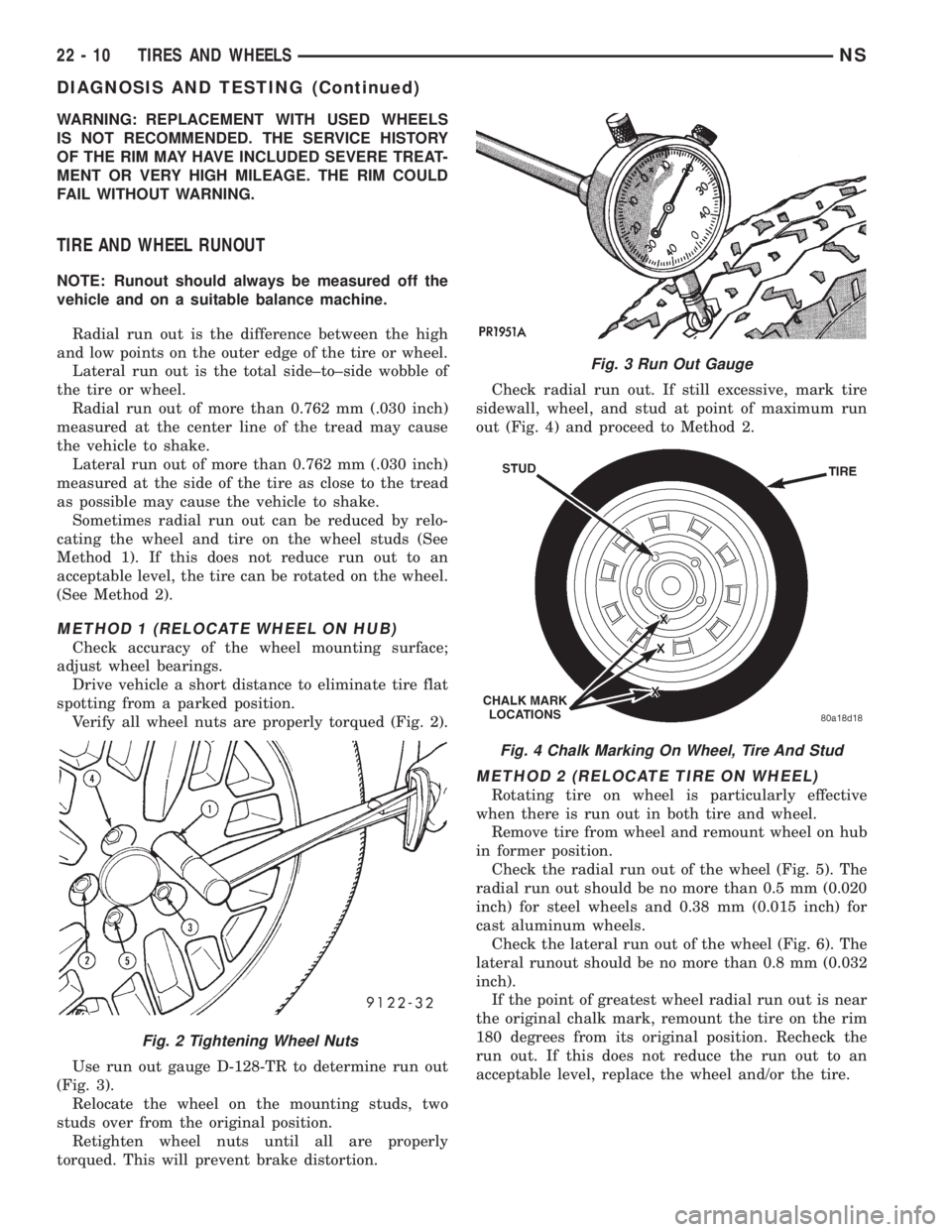
Verify all wheel nuts are properly torqued (Fig. 2).
Use run out gauge D-128-TR to determine run out
(Fig. 3).
Relocate the wheel on the mounting studs, two
studs over from the original position.
Retighten wheel nuts until all are properly
torqued. This will prevent brake distortion.Check radial run out. If still excessive, mark tire
sidewall, wheel, and stud at point of maximum run
out (Fig. 4) and proceed to Method 2.
METHOD 2 (RELOCATE TIRE ON WHEEL)
Rotating tire on wheel is particularly effective
when there is run out in both tire and wheel.
Remove tire from wheel and remount wheel on hub
in former position.
Check the radial run out of the wheel (Fig. 5). The
radial run out should be no more than 0.5 mm (0.020
inch) for steel wheels and 0.38 mm (0.015 inch) for
cast aluminum wheels.
Check the lateral run out of the wheel (Fig. 6). The
lateral runout should be no more than 0.8 mm (0.032
inch).
If the point of greatest wheel radial run out is near
the original chalk mark, remount the tire on the rim
180 degrees from its original position. Recheck the
run out. If this does not reduce the run out to an
acceptable level, replace the wheel and/or the tire.
Fig. 2 Tightening Wheel Nuts
Fig. 3 Run Out Gauge
Fig. 4 Chalk Marking On Wheel, Tire And Stud
22 - 10 TIRES AND WHEELSNS
DIAGNOSIS AND TESTING (Continued)
Page 1754 of 1938
Some water leaks must be tested for a considerable
length of time to become apparent. When a leak
appears, find the highest point of the water track or
drop. The highest point usually will show the point of
entry. After leak point has been found, repair the
leak and water test to verify that the leak has
stopped.
Locating the entry point of water that is leaking
into a cavity between panels can be difficult. The
trapped water may splash or run from the cavity,
often at a distance from the entry point. Most water
leaks of this type become apparent after accelerating,
stopping, turning, or when on an incline.
MIRROR INSPECTION METHOD
When a leak point area is visually obstructed, use
a suitable mirror to gain visual access. A mirror can
also be used to deflect light to a limited-access area
to assist in locating a leak point.
BRIGHT LIGHT LEAK TEST METHOD
Some water leaks in the luggage compartment can
be detected without water testing. Position the vehi-
cle in a brightly lit area. From inside the darkened
luggage compartment inspect around seals and body
seams. If necessary, have a helper direct a drop light
over the suspected leak areas around the luggage
compartment. If light is visible through a normally
sealed location, water could enter through the open-
ing.
PRESSURIZED LEAK TEST METHOD
When a water leak into the passenger compart-
ment cannot be detected by water testing, pressurize
the passenger compartment and soap test exterior of
the vehicle. To pressurize the passenger compart-
ment, close all doors and windows, start engine, and
set heater control to high blower in HEAT position. If
engine can not be started, connect a charger to the
battery to ensure adequate voltage to the blower.
With interior pressurized, apply dish detergent solu-
tion to suspected leak area on the exterior of the
vehicle. Apply detergent solution with spray device or
soft bristle brush. If soap bubbles occur at a body
seam, joint, seal or gasket, the leak entry point could
be at that location.
WIND NOISE
Wind noise is the result of most air leaks. Air leaks
can be caused by poor sealing, improper body compo-
nent alignment, body seam porosity, or missing plugs
in the engine compartment or door hinge pillar areas.
All body sealing points should be airtight in normal
driving conditions. Moving sealing surfaces will not
always seal airtight under all conditions. At times,
side glass or door seals will allow wind noise to be
noticed in the passenger compartment during highcrosswinds. Over compensating on door or glass
adjustments to stop wind noise that occurs under
severe conditions can cause premature seal wear and
excessive closing or latching effort. After a repair pro-
cedure has been performed, test vehicle to verify
noise has stopped before returning vehicle to use.
Wind noise can also be caused by improperly fitted
exterior moldings or body ornamentation. Loose
moldings can flutter, creating a buzzing or chattering
noise. An open cavity or protruding edge can create a
whistling or howling noise. Inspect the exterior of the
vehicle to verify that these conditions do not exist.
VISUAL INSPECTION BEFORE TESTS
Verify that floor and body plugs are in place and
body components are aligned and sealed. If component
alignment or sealing is necessary, refer to the appro-
priate section of this group for proper procedures.
ROAD TESTING WIND NOISE
(1) Drive the vehicle to verify the general location
of the wind noise.
(2) Apply 50 mm (2 in.) masking tape in 150 mm
(6 in.) lengths along weatherstrips, weld seams or
moldings. After each length is applied, drive the vehi-
cle. If noise goes away after a piece of tape is applied,
remove tape, locate, and repair defect.
POSSIBLE CAUSE OF WIND NOISE
²Moldings standing away from body surface can
catch wind and whistle.
²Gaps in sealed areas behind overhanging body
flanges can cause wind-rushing sounds.
²Misaligned movable components.
²Missing or improperly installed plugs in pillars.
²Weld burn through holes.
SERVICE PROCEDURES
HEAT STAKING
(1) Remove trim panel.
(2) Bend or move the trim panel components at
the heat staked joints. Observe the heat staked loca-
tions and/or component seams for looseness.
(3) Heat stake the components.
(a) If the heat staked or component seam loca-
tion is loose, hold the two components tightly
together and using a soldering gun with a flat tip,
melt the material securing the components
together. Do not over heat the affected area, dam-
age to the exterior of the trim panel may occur.
(b) If the heat staked material is broken or miss-
ing, use a hot glue gun to apply new material to
the area to be repaired. The panels that are being
heat staked must be held together while the apply-
ing the glue. Once the new material is in place, it
23 - 24 BODYNS
DIAGNOSIS AND TESTING (Continued)
Page 1838 of 1938
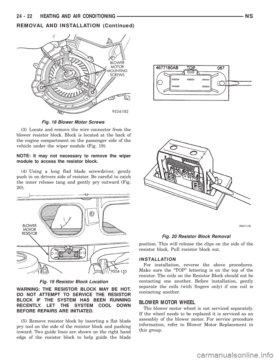
(3) Locate and remove the wire connector from the
blower resistor block. Block is located at the back of
the engine compartment on the passenger side of the
vehicle under the wiper module (Fig. 19).
NOTE: It may not necessary to remove the wiper
module to access the resistor block.
(4) Using a long flad blade screwdriver, gently
push in on drivers side of resistor. Be careful to catch
the inner release tang and gently pry outward (Fig.
20).
WARNING: THE RESISTOR BLOCK MAY BE HOT.
DO NOT ATTEMPT TO SERVICE THE RESISTOR
BLOCK IF THE SYSTEM HAS BEEN RUNNING
RECENTLY. LET THE SYSTEM COOL DOWN
BEFORE REPAIRS ARE INITIATED.
(5) Remove resistor block by inserting a flat blade
pry tool on the side of the resistor block and pushing
inward. Two guide lines are shown on the right hand
edge of the resistor block to help guide the bladeposition. This will release the clips on the side of the
resistor block. Pull resistor block out.
INSTALLATION
For installation, reverse the above procedures.
Make sure the ªTOPº lettering is on the top of the
resistor. The coils on the Resistor Block should not be
contacting one another. Before installation, gently
separate the coils (with fingers only) if one coil is
contacting another.
BLOWER MOTOR WHEEL
The blower motor wheel is not serviced separately.
If the wheel needs to be replaced it is serviced as an
assembly of the blower motor. For service procedure
information, refer to Blower Motor Replacement in
this group.
Fig. 18 Blower Motor Screws
Fig. 19 Resistor Block Location
Fig. 20 Resistor Block Removal
24 - 22 HEATING AND AIR CONDITIONINGNS
REMOVAL AND INSTALLATION (Continued)