1996 ACURA RL KA9 reset
[x] Cancel search: resetPage 1521 of 1954
8. Afte r reconnectin g th e battery , ente r th e anti-thef t
cod e fo r th e radi o an d th e navigatio n system , the n
ente r th e customer' s radi o statio n presets .
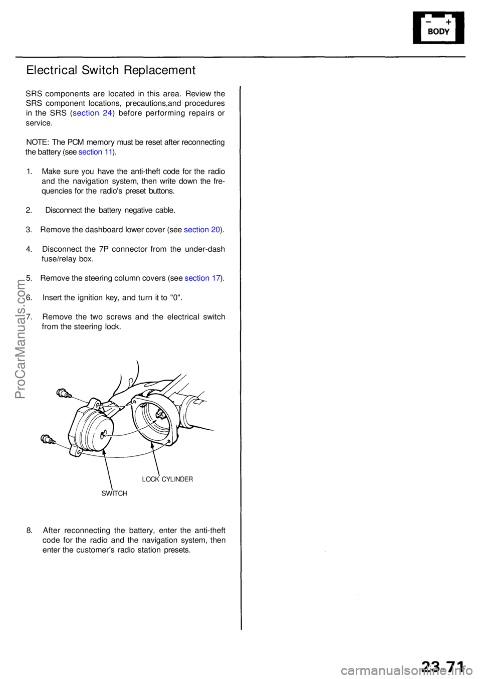
SWITCH
LOCK CYLINDE R
Electrical Switc h Replacemen t
SRS component s ar e locate d i n thi s area . Review the
SR S componen t locations , precautions,an d procedure s
i n th e SR S ( sectio n 24 ) befor e performin g repair s o r
service .
NOTE: Th e PC M memor y mus t b e rese t afte r reconnectin g
th e batter y (se e sectio n 11 ).
1 . Mak e sur e yo u hav e th e anti-thef t cod e fo r th e radi o
an d th e navigatio n system , the n writ e dow n th e fre -
quencie s fo r th e radio' s prese t buttons .
2 . Disconnec t th e batter y negativ e cable .
3 . Remov e th e dashboar d lowe r cove r (se e sectio n 20 ).
4 . Disconnec t th e 7 P connecto r fro m th e under-das h
fuse/rela y box .
5 . Remov e th e steerin g colum n cover s (se e sectio n 17 ).
6 . Inser t th e ignitio n key , an d tur n it t o "0" .
7 . Remov e th e tw o screw s an d th e electrica l switc h
fro m th e steerin g lock .
ProCarManuals.com
Page 1526 of 1954
Gauge Assembl y
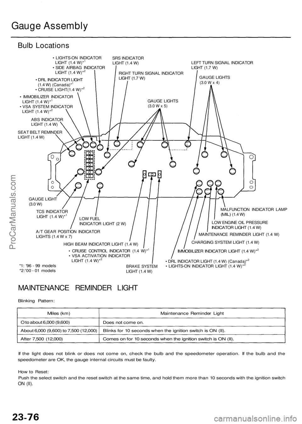
Bulb Location s
• LIGHTS-O N INDICATO R
LIGH T (1. 4 W)*1
• SID E AIRBA G INDICATO R
LIGH T (1. 4 W)*2
SR S INDICATO R
LIGH T (1. 4 W )
RIGH T TUR N SIGNA L INDICATO R
LIGHT (1. 7 W )
GAUG E LIGHT S(3.0 W x 5)
• DR L INDICATO R LIGH T(1.4 W ) (Canada)*1
• CRUIS E LIGHT(1. 4 W)*2
• IMMOBILIZE R INDICATO R
LIGH T (1. 4 W)*1
• VS A SYSTE M INDICATO R
LIGH T (1. 4 W)*2
AB S INDICATO R
LIGH T (1. 4 W )
SEA T BEL T REMINDE R
LIGH T (1. 4 W ) LEF
T TUR N SIGNA L INDICATO R
LIGH T (1. 7 W )
GAUG E LIGHT S
(3.0 W x 4)
MALFUNCTIO N INDICATO R LAM P(MIL) (1.4 W)
LO W ENGIN E OI L PRESSUR EINDICATOR LIGH T (1. 4 W )
MAINTENANC E REMINDE R LIGH T (1. 4 W )
CHARGIN G SYSTE M LIGH T (1. 4 W )
IMMOBILIZE R INDICATO R LIGH T (1. 4 W)*2
• DR L INDICATO R LIGH T (1. 4 W ) (Canada)*2
• LIGHTS-O N INDICATO R LIGH T (1. 4 W)*2BRAK E SYSTE MLIGHT (1. 4 W )
A/
T GEA R POSITIO N INDICATO R
LIGHT S (1. 4 W x 7) LO
W FUE L
INDICATO R LIGH T ( 2 W )
TC
S INDICATO R
LIGH T (1. 4 W)*
1
GAUG E LIGH T(3.0 W )
HIG H BEA M INDICATO R LIGH T (1. 4 W )
• CRUIS E CONTRO L INDICATO R (1. 4 W)*1
• VS A ACTIVATIO N INDICATO R
LIGH T (1. 4 W)*2
*1 : '9 6 - 9 9 model s*2:'00 - 0 1 model s
MAINTENANC E REMINDE R LIGH T
Blinking Pattern :
Miles (km ) Maintenance Reminde r Ligh t
O to abou t 6,00 0 (9,600 )
Does no t com e on .
Abou t 6,00 0 (9,600 ) t o 7,50 0 (12,000 )Blink s fo r 1 0 second s whe n th e ignitio n switc h is O N (II) .
Come s o n fo r 1 0 second s whe n th e ignitio n switc h is O N (II) .Afte r 7,50 0 (12,000 )
I f th e ligh t doe s no t blin k o r doe s no t com e on , chec k th e bul b an d th e speedomete r operation . I f th e bul b an d th e
speedomete r ar e OK , th e gaug e interna l circuit s mus t b e faulty .
How to Reset :
Push th e selec t switc h an d th e rese t switc h a t th e sam e time , an d hol d the m mor e tha n 1 0 second s wit h th e ignitio n switc h
ON (II) .
ProCarManuals.com
Page 1548 of 1954
Headlights
HID Bul b Remova l ('9 9 - 0 4 models )
A transien t hig h tensio n (25,00 0 V ) occur s
a t th e bul b socket s o f th e hig h intensit y discharg e (HID )
lamp s whe n th e combinatio n ligh t switc h is turne d ON .
I t ma y caus e seriou s electrica l shoc k o r electrocutio n if
yo u d o no t observ e th e caution s below .
CAUTION :
• Neve r tur n o n th e combinatio n ligh t switc h befor e
fittin g th e HI D bulb s t o thei r bul b socket s an d com -
pletin g th e reassembl y o f th e headligh t assembly .
• T o preven t electrocution , d o no t servic e th e head -
light s assembl y i n we t conditions , suc h a s rai n o r
snow , nea r a sprinkle r system , o r whe n you r hand s
are wet .
• D o no t touc h th e surfac e o f th e HI D bulb s wit h you r
bar e hand s an d d o no t stai n i t wit h an y oil s an d
fats .
• D o no t disassembl e th e inverte r uni t an d th e ignite r
unit .
• D o no t tur n o n th e HI D bul b b y usin g a powe r
sourc e othe r tha n th e batter y mounte d o n you r
vehicle .
1. Mak e sur e yo u hav e th e anti-thef t cod e fo r th e radi o
an d th e navigatio n system , the n writ e dow n th e fre -
quencie s fo r th e radio' s prese t buttons .
2. Tur n th e combinatio n ligh t switc h OFF .
3. Disconnec t th e batter y negativ e cable , the n discon -
nec t th e positiv e cable .
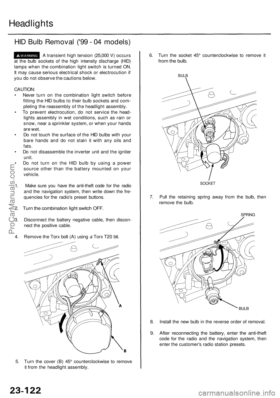
4 . Remov e th e Tor x bol t (A ) usin g a Tor x T2 0 bit .
5 . Tur n th e cove r (B ) 45 ° counterclockwis e t o remov e
i t fro m th e headligh t assembly . 8
. Instal l th e ne w bul b in th e revers e orde r o f removal .
9. Afte r reconnectin g th e battery , ente r th e anti-thef t
code fo r th e radi o an d th e navigatio n system , the n
ente r th e customer' s radi o statio n presets .
BULB
SPRIN G
6. Tur n th e socke t 45 ° counterclockwis e t o remov e i t
fro m th e bulb .
BULB
7. Pul l th e retainin g sprin g awa y fro m th e bulb , the n
remov e th e bulb .
SOCKE T
ProCarManuals.com
Page 1567 of 1954
Stereo Soun d Syste m
Audio Uni t Remova l
SRS component s ar e locate d i n thi s area . Revie w th e
SR S componen t locations , precautions , an d procedure s
i n th e SR S ( sectio n 24 ) befor e performin g repair s o r
service .
With navigatio n system :
1 . Mak e sur e yo u hav e th e anti-thef t cod e fo r th e radi o
an d th e navigatio n system , the n writ e dow n th e fre -
quencie s fo r th e radio' s prese t buttons .
2 . Remov e th e navigatio n pane l an d audi o pane l
assembl y (se e sectio n 20 ).
3 . Remov e th e fou r mountin g screws , the n remov e th e
navigatio n monitor .
4. Loose n th e audi o uni t mountin g screws .
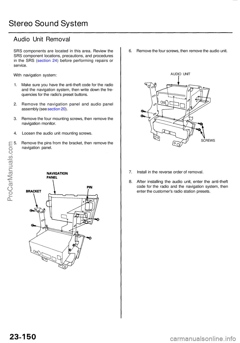
5 . Remov e th e pin s fro m th e bracket , the n remov e th e
navigatio n panel .
7. Instal l i n th e revers e orde r o f removal .
8. Afte r installin g th e audi o unit , ente r th e anti-thef t
code fo r th e radi o an d th e navigatio n system , the n
ente r th e customer' s radi o statio n presets .
6
. Remov e th e fou r screws , the n remov e th e audi o unit .
AUDI O UNI T
SCREW S
ProCarManuals.com
Page 1568 of 1954
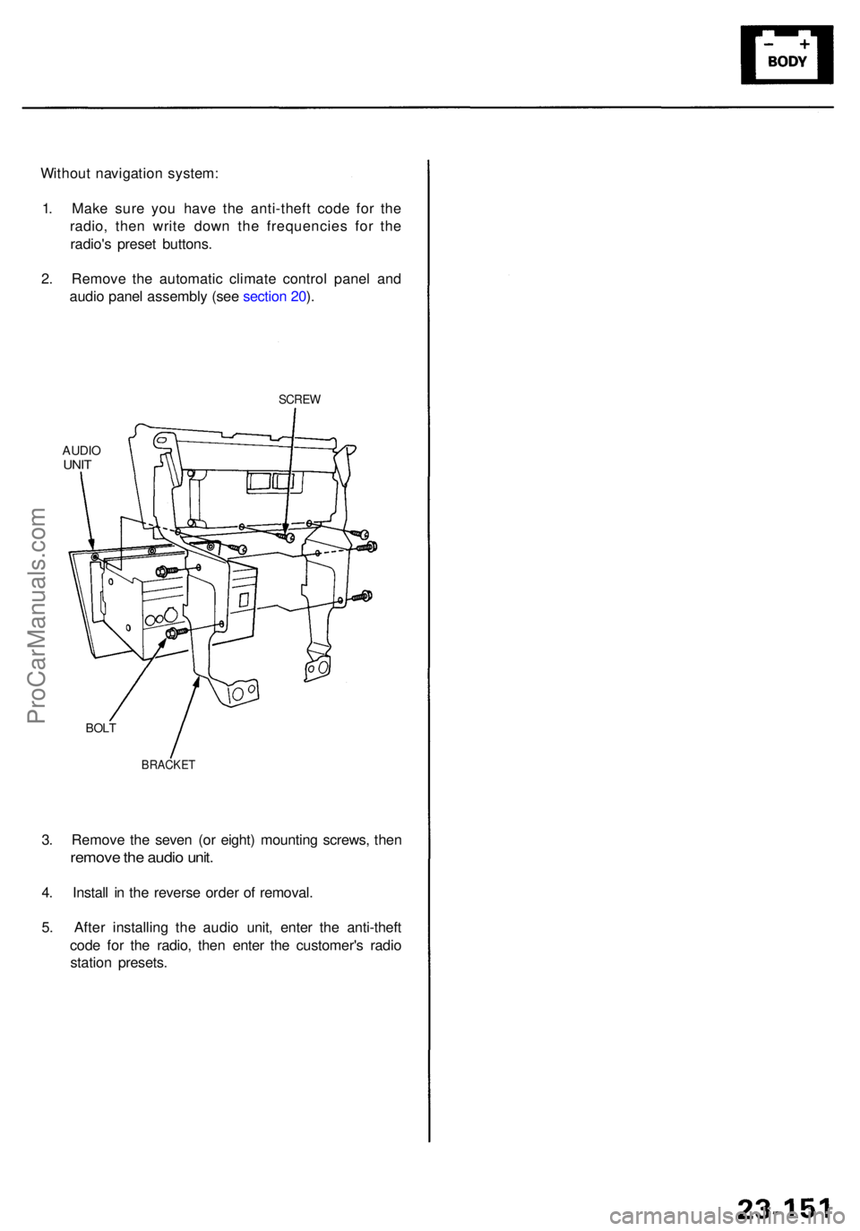
3. Remov e th e seve n (o r eight ) mountin g screws , the n
remov e th e audi o unit .
4. Instal l i n th e revers e orde r o f removal .
5 . Afte r installin g th e audi o unit , ente r th e anti-thef t
cod e fo r th e radio , the n ente r th e customer' s radi o
statio n presets .
Withou
t navigatio n system :
1 . Mak e sur e yo u hav e th e anti-thef t cod e fo r th e
radio , the n writ e dow n th e frequencie s fo r th e
radio' s prese t buttons .
2 . Remov e th e automati c climat e contro l pane l an d
audi o pane l assembl y (se e sectio n 20 ).
SCRE W
AUDIOUNIT
BRACKE T
BOLT
ProCarManuals.com
Page 1578 of 1954
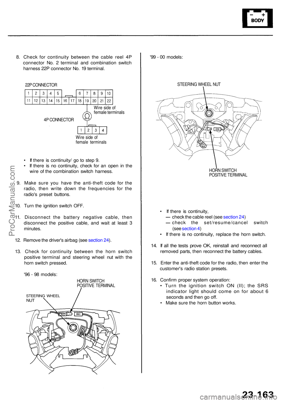
8. Chec k fo r continuit y betwee n th e cabl e ree l 4 P
connecto r No . 2 termina l an d combinatio n switc h
harnes s 22 P connecto r No . 1 9 terminal .
22P CONNECTO R
4 P CONNECTO R
Wir e sid e o f
femal e terminal s
Wir
e sid e o f
femal e terminal s
• I f ther e i s continuity / g o t o ste p 9 .
• I f ther e i s n o continuity , chec k fo r a n ope n i n th e
wir e o f th e combinatio n switc h harness .
9 . Mak e sur e yo u hav e th e anti-thef t cod e fo r th e
radio , the n writ e dow n th e frequencie s fo r th e
radio' s prese t buttons .
10 . Tur n th e ignitio n switc h OFF .
11 . Disconnec t th e batter y negativ e cable , the n
disconnec t th e positiv e cable , an d wai t a t leas t 3
minutes .
12 . Remov e th e driver' s airba g (se e sectio n 24 ).
13 . Chec k fo r continuit y betwee n th e hor n switc h
positiv e termina l an d steerin g whee l nu t wit h th e
hor n switc h pressed .
HORN SWITC H
POSITIV E TERMINA L
STEERING WHEE LNUT
'96 - 9 8 models : '9
9 - 0 0 models :
STEERIN G WHEE L NU T
HOR N SWITC H
POSITIV E TERMINA L
• I f ther e i s continuity ,
chec k th e cabl e ree l (se e sectio n 24 )
chec k th e set/resume/cance l switc h
(se e sectio n 4 )
• I f ther e i s n o continuity , replac e th e hor n switch .
14. I f al l th e test s prov e OK , reinstal l an d reconnec t al l
remove d parts , the n reconnec t th e batter y cables .
15 . Ente r th e anti-thef t cod e fo r th e radio , the n ente r th e
customer' s radi o statio n presets .
16 . Confir m prope r syste m operation :
• Tur n th e ignitio n switc h O N (II) ; th e SR S
indicato r ligh t shoul d com e o n fo r abou t 6
second s an d the n g o off .
• Mak e sur e th e hor n butto n works .
ProCarManuals.com
Page 1603 of 1954
Driving Positio n Memor y Syste m (DPMS )
Self-diagnosti c Procedure s
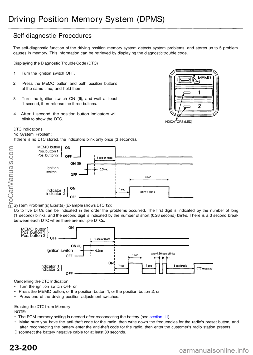
The self-diagnosti c functio n o f th e drivin g positio n memor y syste m detect s syste m problems , an d store s u p t o 5 proble m
cause s i n memory . This informatio n ca n b e retrieve d b y displayin g th e diagnosti c troubl e code .
Displayin g th e Diagnosti c Troubl e Cod e (DTC )
1 . Tur n th e ignitio n switc h OFF .
2 . Pres s th e MEM O butto n an d bot h positio n button s
a t th e sam e time , an d hol d them .
3 . Tur n th e ignitio n switc h O N (II) , an d wai t a t leas t
1 second , the n releas e th e thre e buttons .
4. Afte r 1 second , th e positio n butto n indicator s wil l
blin k t o sho w th e DTC .
DT C Indication s
N o Syste m Problem :
I f ther e is n o DT C stored , th e indicator s blin k onl y onc e ( 3 seconds) .INDICATOR S (LED )
Indicato r 1
indicato r 2
Ignitio n
switc h
MEM O butto nPos. butto n 1
Pos . butto n 2
Syste m Problem(s ) Exist(s ) (Exampl e show s DT C 12) :
U p t o fiv e DTC s ca n b e indicate d i n th e orde r th e problem s occurred . Th e firs t digi t i s indicate d b y th e numbe r o f lon g
( 1 second ) blinks , an d th e secon d digi t i s indicate d b y th e numbe r o f shor t (0.2 6 second ) blinks . Ther e i s a 3 secon d brea k
betwee n eac h DT C whe n ther e ar e multipl e DTCs .
MEM O butto n
Pos. butto n 1Pos . butto n 2
Ignitio n switc h
Indicato r 1
Indicato r 2
Cancellin g th e DT C Indicatio n
• Tur n th e ignitio n switc h OF F o r
• Pres s th e MEM O button , o r th e positio n butto n 1 , o r th e positio n butto n 2 , o r
• Pres s on e o f th e drivin g positio n adjustmen t switches .
Erasin g th e DT C fro m Memor y
NOTE:
• Th e PC M memor y settin g is neede d afte r reconnectin g th e batter y (se e sectio n 11 ).
• Mak e sur e yo u hav e th e anti-thef t cod e fo r th e radio , the n writ e dow n th e frequencie s fo r th e radio' s prese t button , an d
afte r reconnectin g th e batter y ente r th e anti-thef t cod e fo r th e radio , the n ente r th e customer' s radi o statio n presets .
Disconnec t th e batter y negativ e cabl e fo r a t leas t 3 0 seconds .
ProCarManuals.com
Page 1747 of 1954
SYSTEM LINK S
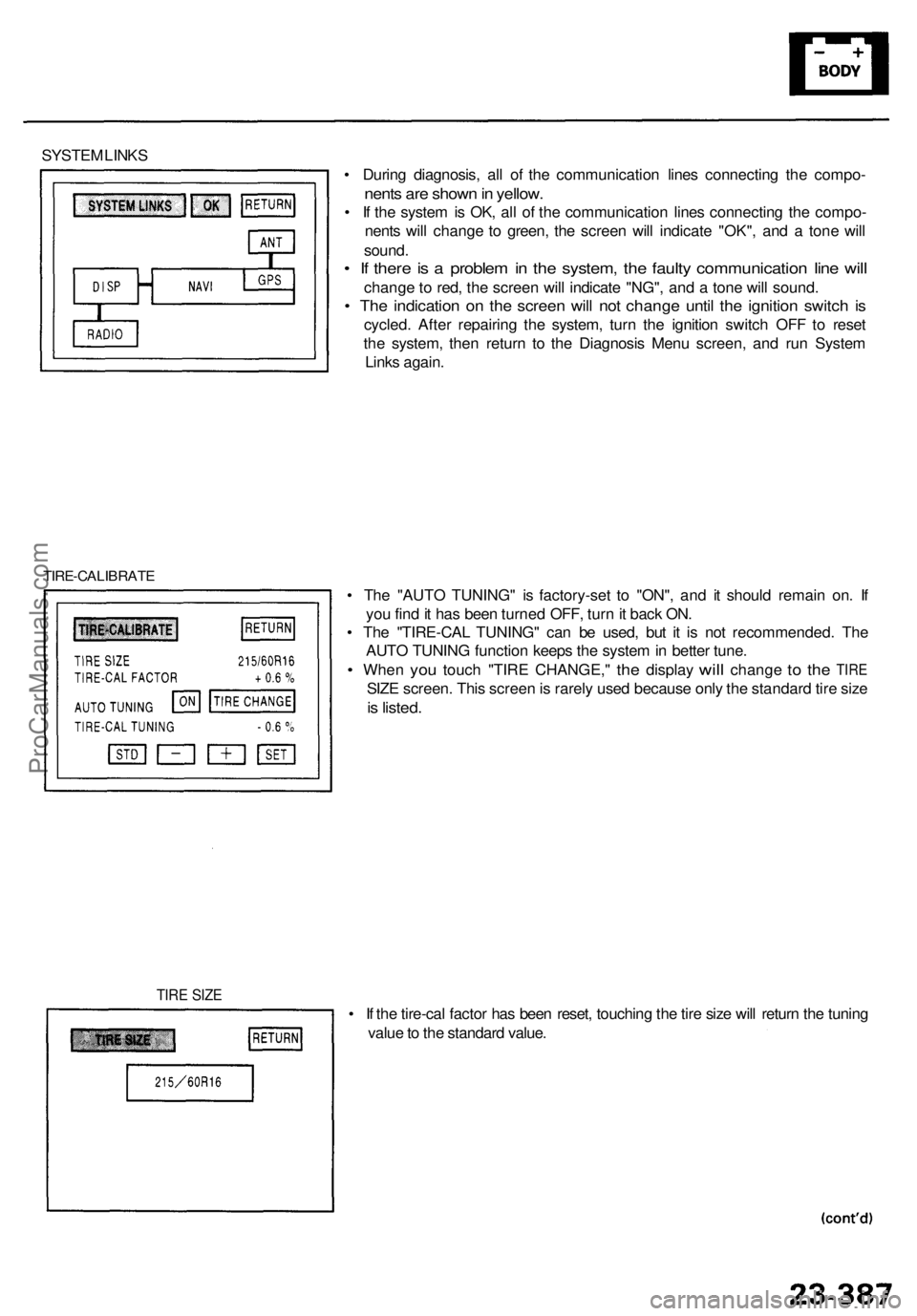
• Durin g diagnosis , al l o f th e communicatio n line s connectin g th e compo -
nents ar e show n in yellow .
• I f th e syste m is OK , al l o f th e communicatio n line s connectin g th e compo -
nent s wil l chang e t o green , th e scree n wil l indicat e "OK" , an d a ton e wil l
sound .
• I f ther e is a proble m in th e system , th e fault y communicatio n lin e wil l
chang e to red , th e scree n wil l indicat e "NG" , an d a ton e wil l sound .
• Th e indicatio n o n th e scree n wil l no t chang e unti l th e ignitio n switc h i s
cycled . Afte r repairin g th e system , tur n th e ignitio n switc h OF F t o rese t
th e system , the n retur n t o th e Diagnosi s Men u screen , an d ru n Syste m
Link s again .
TIRE-CALIBRAT E
• Th e "AUT O TUNING " i s factory-se t t o "ON" , an d i t shoul d remai n on . I f
yo u fin d it ha s bee n turne d OFF , tur n it bac k ON .
• Th e "TIRE-CA L TUNING " ca n b e used , bu t i t i s no t recommended . Th e
AUT O TUNIN G functio n keep s th e syste m in bette r tune .
• Whe n you touc h "TIR E CHANGE, " the displa y will chang e to th e TIR E
SIZE screen . Thi s scree n is rarel y use d becaus e onl y th e standar d tir e siz e
is listed .
• I f th e tire-ca l facto r ha s bee n reset , touchin g th e tir e siz e wil l retur n th e tunin g
valu e to th e standar d value .
TIRE SIZ E
ProCarManuals.com