1996 ACURA RL KA9 reset
[x] Cancel search: resetPage 426 of 1954

Cylinder Heads
Installation (cont'd)
4. Install the cylinder heads on the cylinder block.
5. Tighten the cylinder head bolts sequentially in 2 or
3 steps.
Specified Torque:
76 N-m (7.8 kgf-m, 56 Ibf-ft)
NOTE:
We recommend using a beam-type torque wrench.
When using a preset-type torque wrench, be sure
to tighten slowly and not to overtighten.
If a bolt makes any noise while you are torquing
it, loosen the bolt and retighten it.
CYLINDER HEAD BOLTS TORQUE SEQUENCE
CYLINDER HEAD BOLTS
Apply engine oil to the bolt
threads.
6. Install the head cover gasket in the groove of the
cylinder head cover. Seat the recesses for the cam-
shaft first, then work it into the groove around the
outside edges.
NOTE:
Before installing the cylinder head cover gasket,
thoroughly clean the seal and the groove.
When installing, make sure the head cover gasket
is seated securely in the corners of the recesses
with no gap.
CORNERS OF
THE RECESS
HEAD COVER
GASKET
Clean.
CORNERS OF
THE RECESS
CYLINDER
HEAD COVER
7. Apply liquid gasket to the head cover gasket at the
four corners of the recesses.
NOTE:
Use liquid gasket, Part No. 08718 - 0001 or 08718
- 0003.
Check that the mating surfaces are clean and dry
before applying liquid gasket.
Do not install the parts if five minutes or more have
elapsed since applying liquid gasket. Instead, reap-
ply liquid gasket after removing old residue.
After assembly, wait at least 30 minutes before
filling the engine with oil.
Apply liquid gasket to
the shaded areas.ProCarManuals.com
Page 428 of 1954

Cylinder Head s
Installatio n (cont'd )
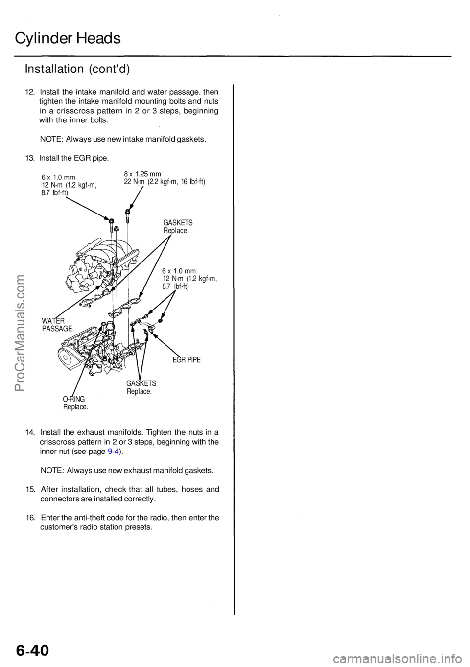
12. Instal l th e intak e manifol d an d wate r passage , the n
tighte n th e intak e manifol d mountin g bolt s an d nut s
i n a crisscros s patter n i n 2 o r 3 steps , beginnin g
wit h th e inne r bolts .
NOTE : Alway s us e ne w intak e manifol d gaskets .
13 . Instal l th e EG R pipe .
6 x 1. 0 m m12 N- m (1. 2 kgf-m ,
8. 7 Ibf-ft )
8 x 1.2 5 mm22 N- m (2. 2 kgf-m , 1 6 Ibf-ft )
GASKET S
Replace.
6 x 1. 0 m m12 N- m (1. 2 kgf-m ,
8. 7 Ibf-ft )
WATE R
PASSAG E
EGR PIP E
GASKET S
Replace.O-RING
Replace .
14. Instal l th e exhaus t manifolds . Tighte n th e nut s i n a
crisscros s patter n in 2 or 3 steps , beginnin g wit h th e
inne r nu t (se e pag e 9-4 ).
NOTE : Alway s us e ne w exhaus t manifol d gaskets .
15 . Afte r installation , chec k tha t al l tubes , hose s an d
connector s ar e installe d correctly .
16 . Ente r th e anti-thef t cod e fo r th e radio , the n ente r th e
customer' s radi o statio n presets .
ProCarManuals.com
Page 540 of 1954

II. Powertrai n Contro l Modul e (PCM ) Rese t Procedur e
NOTE : Th e PC M memor y settin g is neede d afte r resettin g th e PC M (se e pag e 11-125 ).
Eithe r o f th e followin g action s wil l rese t th e PCM .
• Us e th e OB D II sca n too l o r Hond a PG M Teste r t o clea r th e PCM' s memory .
NOTE : Se e th e OB D II sca n too l o r Hond a PG M Teste r user' s manual s fo r specifi c operatin g instructions .
• Tur n th e ignitio n switc h OFF . Remov e th e BAC K U P RADI O (7. 5 A ) fus e fro m th e under-hoo d fuse/rela y bo x fo r
1 0 seconds .
NOTE : I f th e BAC K U P RADI O (7. 5 A ) fus e i s remove d an d th e ignitio n switc h O N (II) , MI L wil l repor t o n an d
BAC K U P RADI O
(7. 5 A ) FUS EPCM wil l stor e th e DT C P0560 .
UNDER-HOO DFUSE/RELA YBOX
III. Fina l Procedur e (thi s procedur e mus t b e don e afte r an y troubleshooting )
1 . Remov e th e SC S servic e connecto r i f i t i s connected .
NOTE : I f th e SC S servic e connecto r i s connecte d an d ther e ar e n o DTC s store d i n th e PCM , th e MI L wil l sta y
on whe n th e ignitio n switc h is turne d O N (II) .
2. D o th e PC M Rese t Procedure .
3 . Tur n th e ignitio n switc h OFF .
4 . Disconnec t th e OB D II sca n too l o r Hond a PG M Teste r fro m th e Dat a Lin k Connector .
ProCarManuals.com
Page 557 of 1954

Troubleshooting
How to Read Flowcharts
A flowchart is designed to be used from start to final repair. It's like a map showing you the shortest distance. But beware:
if you go off the "map" anywhere but a "stop" symbol, you can easily get lost.
Describes the conditions or situation to start a troubleshooting flowchart.
Asks you to do something; perform a test, set up a condition etc.
Asks you about the result of an action, then sends you in the appropriate troubleshooting direction.
(bold type)
The end of a series of actions and decisions, describes a final repair action and sometimes directs you to
an earlier part of the flowchart to confirm your repair.
NOTE:
• The term "Intermittent Failure" is used in these charts. It simply means a system may have had a failure, but it checks
out OK at this time. If the Malfunction Indicator Lamp (MIL) on the dash does not come on, check for poor connections
or loose wires at all connectors related to the circuit that you are troubleshooting (see illustration below).
• Most of the troubleshooting flowcharts have you reset the Powertrain Control Module (PCM) and try to duplicate the
Diagnostic Trouble Code (DTC). If the problem is intermittent and you can't duplicate the code, do not continue through
the flowchart. To do so will only result in confusion and, possibly, a needlessly replaced PCM.
• "Open" and "Short" are common electrical terms. An open is a break in a wire or at a connection. A short is an acci-
dental connection of a wire to ground or to another wire. In simple electronics, this usually means something won't
work at all. In complex electronics (like PCM's), this can sometimes mean something works, but not the way it's sup-
posed to.
TIGHT
LOOSE
(bold type)ProCarManuals.com
Page 589 of 1954

PGM-FI System
Secondary Heated Oxygen Sensor (HO2S) (Sensor 2) (cont'd)
Does the voltage stay within
0.3 - 0.6 V for 2 minutes?
NO
Intermittent failure, system is OK
at this time. Check for poor con-
nections or loose wires at C444
(located behind right kick panel),
C610 (secondary HO2S (Sensor
2)) and
PCM.
The scan tool indicates Diagnostic Trouble Code (DTC) P0139: A slow response problem in the Secondary
Heated Oxygen Sensor (Secondary HO2S) (Sensor 2) circuit.
— The MIL has been reported on.
— DTC P0139 is stored.
Problem verification:
1. Do the PCM Reset Procedure.
2. Start the engine. Hold the
engine at 3,000 rpm with no
load (in Park or neutral) until
the radiator fan comes on.
3. Check the secondary HO2S
(Sensor 2) or output at 3,000
rpm with the scan tool.
Replace the secondary HO2S (Sen-
sor 2).
YESProCarManuals.com
Page 624 of 1954

6. Tur n th e ignitio n switc h OFF .
7. Reconnec t th e 2 P connecto r o n th e IA C valve , the n
d o th e PC M rese t procedure .
NOTE : Th e PC M memor y settin g i s neede d afte r
resettin g th e PCM .
8 . Restar t an d idl e th e engin e wit h no-loa d condition s
fo r on e minute , the n chec k th e idl e speed .
NOTE : (Canada ) Pul l th e parkin g brak e leve r up .
Star t th e engine , the n chec k tha t th e headlight s ar e
off.
Idle spee d shoul d be :
650 5 0 rp m
(in Par k o r neutral )
NOTE: I f th e idl e spee d i s no t withi n specification ,
se e Sympto m Char t o n pag e 11-44 .
ProCarManuals.com
Page 625 of 1954

PCM Memory Setting
NOTE: The PCM reset procedure and disconnecting the
battery or the BACK UP RADIO (7.5 A) fuse cancels the
PCM memory for idle control. The following procedure
is needed after the PCM reset procedure and reconnect-
ing the battery or the BACK UP RADIO (7.5 A) fuse.
1. Start the engine. Hold the engine at 3,000 rpm with
no load (in Park or neutral) until the radiator fan
comes on.
2. Let the engine idle for approx. 5 minutes under the
following conditions:
• Transmission in Park or neutral
• A/C switch OFF
• Headlights OFF
• Rear defogger OFFProCarManuals.com
Page 632 of 1954

Fuel Suppl y Syste m
System Descriptio n
The fue l suppl y syste m consist s o f a fue l tank , in-tan k
high-pressur e fue l pump , PGM-F I mai n relay , fue l filter ,
fue l pressur e regulator , fue l pressur e regulato r contro l
solenoi d valve , injectors , an d fue l deliver y an d retur n
lines . Thi s syste m deliver s pressure-regulate d fue l t o th e
injector s an d cut s th e fue l deliver y whe n th e engin e i s
no t running .
Fuel Pressur e
Relieving
Befor e disconnectin g fue l pipe s o r hoses , releas e pres -
sur e fro m th e syste m b y loosenin g th e servic e bol t o n
top o f th e fue l filter .
SERVIC E
BOL T
12 N- m(1.2 kgf-m , 8. 7 Ibf-ft )
FUE L
FILTE R
SHOP TOWE L
NOTE:
• A fue l pressur e gaug e can be attache d a t th e ser -
vic e bol t hole .
• Alway s replac e th e washe r betwee n th e servic e
bol t an d th e specia l banj o bol t wheneve r th e ser -
vic e bol t i s loosened .
• Replac e al l washer s wheneve r th e bolt s ar e
removed . Inspectio
n
1 . Reliev e fue l pressure .
2 . Remov e th e servic e bol t o n th e fue l filte r whil e hold -
in g th e banj o bol t wit h anothe r wrench . Attac h th e
specia l tool .
FUEL FILTE R
3. Star t th e engine . Measur e th e fue l pressur e wit h th e
engin e idlin g an d th e vacuu m hos e o f th e fue l pres -
sur e regulato r disconnecte d fro m th e fue l pressur e
regulato r an d pinched . I f th e engin e wil l no t start ,
turn th e ignitio n switc h O N (II) , wai t fo r tw o sec -
onds , tur n i t OFF , the n bac k o n agai n an d rea d th e
fue l pressure .
Pressur e shoul d be :
29 9 - 34 8 kP a (3.0 5 - 3.5 5 kgf/cm
2, 43. 4 - 50. 5 psi )
4 . Reconnec t vacuu m hos e to th e fue l pressur e regula -
tor.
Pressur e shoul d be :
24 0 - 28 9 kP a (2.4 5 - 2.9 5 kgf/cm2, 34. 8 - 41. 9 psi )
I f th e fue l pressur e i s no t a s specified , firs t chec k th e
fue l pum p (se e pag e 11-142 ). I f th e fue l pum p is OK ,
chec k th e following :
• I f th e fue l pressur e i s highe r tha n specified ,
inspec t for :
— Pinche d o r clogge d fue l retur n hos e o r line .
— Fault y fue l pressur e regulato r (se e pag e
11-135 ).
• I f th e fue l pressur e i s lowe r tha n specified , inspec t
for:
— Clogge d fue l filter .
— Fault y fue l pressur e regulato r (se e pag e
11-135 ).
— Fue l lin e leakage .
1
. Mak e sur e yo u hav e th e anti-thef t cod e fo r th e
radio , the n writ e dow n th e frequencie s fo r th e
radio' s prese t buttons .
2 . Disconnec t th e batter y negativ e cabl e fro m th e bat -
ter y negativ e terminal .
3. Remov e th e fue l fil l cap .
4. Us e a bo x en d wrenc h o n th e servic e bol t a t th e fue l
filte r whil e holdin g th e specia l banj o bol t wit h
anothe r wrench .
5. Plac e a ra g o r sho p towe l ove r th e servic e bolt .
6 . Slowl y loose n th e servic e bol t on e complet e turn .
7 . Reconnec t th e battery , ente r th e anti-thef t cod e fo r
th e radio , the n ente r th e customer' s radi o statio n
presets .
•
D o no t smok e whil e workin g o n th e fue l system .
Kee p ope n flame s o r spark s awa y fro m you r wor k area .
• B e sur e t o reliev e fue l pressur e whil e th e ignitio n
switch is off .
CLAM P
FUE
L
PRESSUR E
REGULATO R FUE
L
PRESSUR E
GAUG E
07406-004000 1
ProCarManuals.com