1996 ACURA RL KA9 reset
[x] Cancel search: resetPage 1779 of 1954
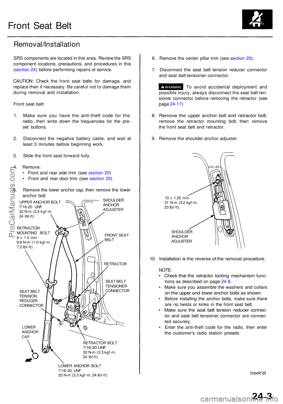
Front Sea t Bel t
Removal/Installatio n
SRS component s ar e locate d in thi s area . Revie w th e SR S
componen t locations , precautions , an d procedure s i n thi s
( sectio n 24 ) befor e performin g repair s o r service .
CAUTION : Chec k th e fron t sea t belt s fo r damage , an d
replac e the n if necessary . B e carefu l no t t o damag e the m
durin g remova l an d installation .
Fron t sea t belt :
1. Mak e sur e yo u hav e th e anti-thef t cod e fo r th e
radio , the n writ e dow n th e frequencie s fo r th e pre -
se t buttons .
2 . Disconnec t th e negativ e batter y cable , an d wai t a t
leas t 3 minute s befor e beginnin g work .
3 . Slid e th e fron t sea t forwar d fully .
4 . Remove :
• Fron t an d rea r sid e tri m (se e sectio n 20 )
• Fron t an d rea r doo r tri m (se e sectio n 20 )
5 . Remov e th e lowe r ancho r cap , the n remov e th e lowe r
ancho r bolt .
SHOULDE R
ANCHO R
ADJUSTE R
UPPER ANCHO R BOL T
7/16-2 0 UN F
3 2 N- m (3. 3 kgf-m ,
24 Ibf-ft )
RETRACTO RMOUNTING BOL T6 x 1. 0 m m9.8 N- m (1. 0 kgf-m ,
7. 2 Ibf-ft )
SEA T BEL T
TENSIO NREDUCE RCONNECTO R
LOWERANCHO RCAP
FRON T SEA TBELT
RETRACTO R
SEAT BEL T
TENSIONE R
CONNECTO R
RETRACTOR BOL T7/16-2 0 UN F32 N- m (3. 3 kgf-m ,24 Ibf-ft )
LOWE R ANCHO R BOL T
7/16-2 0 UN F
3 2 N- m (3. 3 kgf-m , 2 4 Ibf-ft )
6. Remov e th e cente r pilla r tri m (se e sectio n 20 ).
7 . Disconnec t th e sea t bel t tensio n reduce r connecto r
an d sea t bel t tensione r connector .
T o avoi d accidenta l deploymen t an d
possibl e injury , alway s disconnec t th e sea t bel t ten -
sione r connecto r befor e removin g th e retracto r (se e
pag e 24-17 )
8. Remov e th e uppe r ancho r bol t an d retracto r bolt ,
remov e th e retracto r mountin g bolt , the n remov e
th e fron t sea t bel t an d retractor .
9 . Remov e th e shoulde r ancho r adjuster .
10 x 1.2 5 mm31 N- m (3. 2 kgf-m ,
2 3 Ibf-ft )
SHOULDE R
ANCHO R
ADJUSTE R
10. Installatio n is th e revers e o f th e remova l procedure .
NOTE:
• Chec k tha t th e retracto r lockin g mechanis m func -
tions a s described on pag e 24-8 .
• Mak e sur e yo u assembl e th e washer s an d collar s
on th e uppe r an d lowe r ancho r bolt s a s shown .
• Befor e installin g th e ancho r bolts , mak e sur e ther e
ar e n o twist s o r kink s i n th e fron t sea t belt .
• Mak e sur e th e sea t bel t tensio n reduce r connec -
tor an d sea t bel t tensione r connecto r ar e connec -
te d securely .
• Ente r th e anti-thef t cod e fo r th e radio , the n ente r
th e customer' s radi o statio n presets .
ProCarManuals.com
Page 1934 of 1954
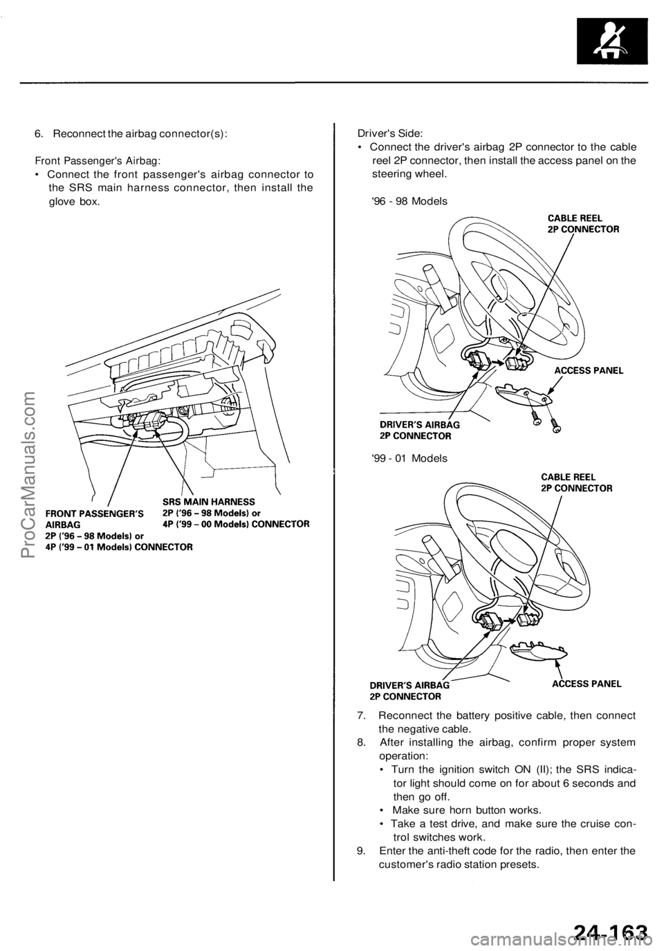
6. Reconnect the airbag connector(s):
Front Passenger's Airbag:
• Connect the front passenger's airbag connector to
the SRS main harness connector, then install the
glove box.
Driver's Side:
• Connect the driver's airbag 2P connector to the cable
reel 2P connector, then install the access panel on the
steering wheel.
'96 - 98 Models
7. Reconnect the battery positive cable, then connect
the negative cable.
8. After installing the airbag, confirm proper system
operation:
• Turn the ignition switch ON (II); the SRS indica-
tor light should come on for about 6 seconds and
then go off.
• Make sure horn button works.
• Take a test drive, and make sure the cruise con-
trol switches work.
9. Enter the anti-theft code for the radio, then enter the
customer's radio station presets.
'99 - 01 ModelsProCarManuals.com
Page 1935 of 1954
Side Airba g
Replacemen t
Store a remove d airba g wit h th e pa d sur -
face u p an d remove d sid e airba g wit h th e cautio n labe l
surfac e up . I f th e sid e airba g i s improperl y store d fac e
down , accidenta l deploymen t coul d prope l th e uni t wit h
enoug h forc e to caus e seriou s injury .
CAUTION :
• D o no t instal l use d SR S part s fro m anothe r vehicle .
Whe n repairing , us e onl y ne w SR S parts .
• Carefull y inspec t th e sid e airba g befor e yo u instal l it .
D o no t instal l a sid e airba g tha t show s sign s o f bein g
droppe d o r improperl y handled , suc h a s dents ,
crack s o r deformation .
• Alway s disconnec t th e sid e airba g connector(s )
whe n th e harnes s is disconnected .
• D o no t disassembl e o r tampe r wit h th e sid e airbag .
1 . Mak e sur e yo u hav e th e anti-thef t cod e fo r th e
radio , the n writ e dow n th e frequencie s fo r th e
radio' s prese t buttons .
2 . Disconnec t th e batter y negativ e cable , the n discon -
nec t th e positiv e cabl e fro m th e battery , an d wai t a t
leas t 3 minutes .
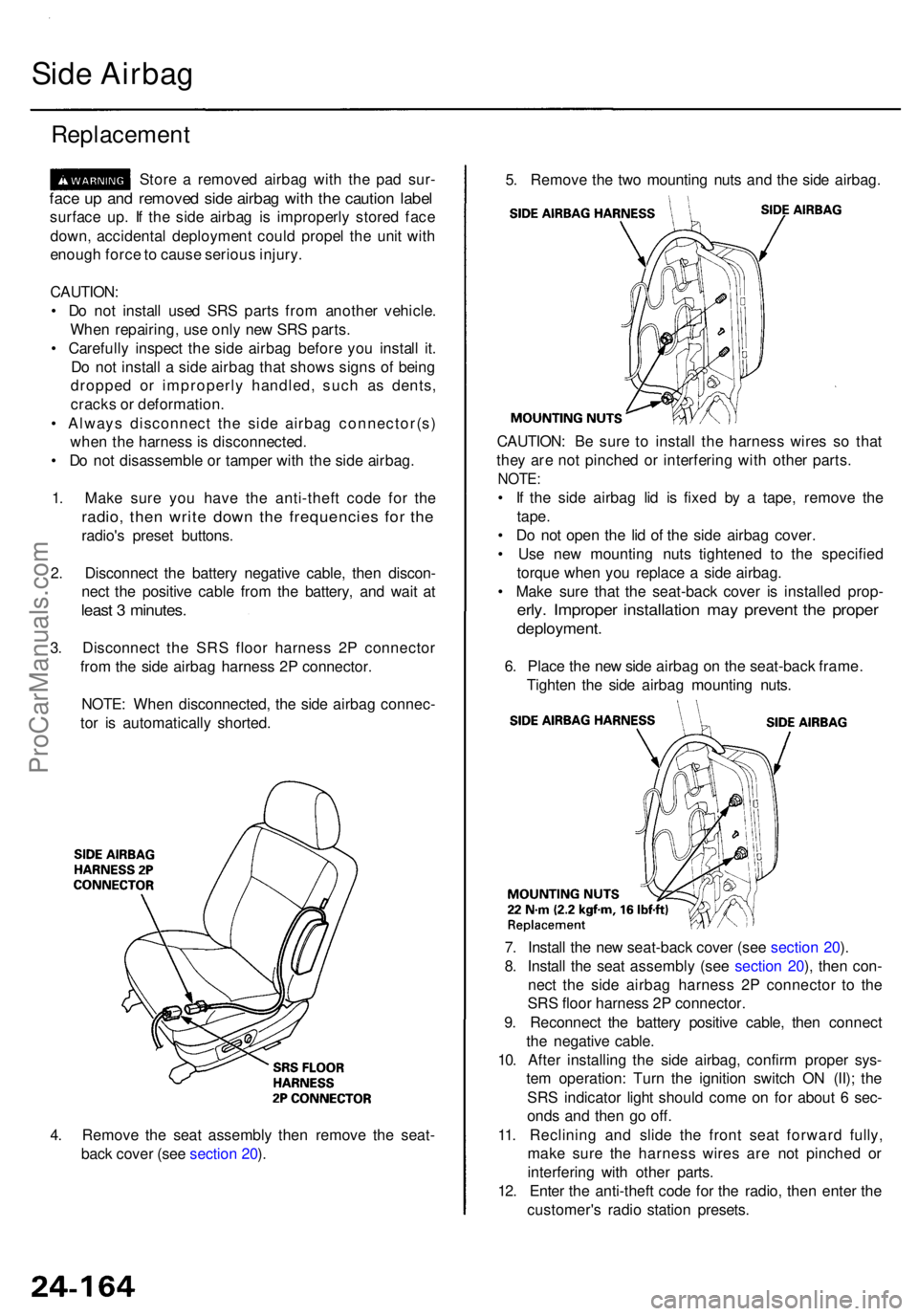
3. Disconnec t th e SR S floo r harnes s 2 P connecto r
fro m th e sid e airba g harnes s 2 P connector .
NOTE : Whe n disconnected , th e sid e airba g connec -
to r i s automaticall y shorted .
4 . Remov e th e sea t assembl y the n remov e th e seat -
bac k cove r (se e sectio n 20 ). 7
. Instal l th e ne w seat-bac k cove r (se e sectio n 20 ).
8 . Instal l th e sea t assembl y (se e sectio n 20 ), the n con -
nec t th e sid e airba g harnes s 2 P connecto r t o th e
SR S floo r harnes s 2 P connector .
9 . Reconnec t th e batter y positiv e cable , the n connec t
th e negativ e cable .
10 . Afte r installin g th e sid e airbag , confir m prope r sys -
te m operation : Tur n th e ignitio n switc h O N (II) ; th e
SR S indicato r ligh t shoul d com e o n fo r abou t 6 sec -
ond s an d the n g o off .
11 . Reclinin g an d slid e th e fron t sea t forwar d fully ,
mak e sur e th e harnes s wire s ar e no t pinche d o r
interfering with othe r parts .
12 . Ente r th e anti-thef t cod e fo r th e radio , the n ente r th e
customer' s radi o statio n presets .
CAUTION
: B e sur e t o instal l th e harnes s wire s s o tha t
the y ar e no t pinche d o r interferin g wit h othe r parts .
NOTE :
• I f th e sid e airba g li d i s fixe d b y a tape , remov e th e
tape .
• D o no t ope n th e li d o f th e sid e airba g cover .
• Us e ne w mountin g nut s tightene d t o th e specifie d
torqu e whe n yo u replac e a sid e airbag .
• Mak e sur e tha t th e seat-bac k cove r i s installe d prop -
erly. Imprope r installatio n ma y preven t th e prope r
deployment .
6. Plac e th e ne w sid e airba g o n th e seat-back frame.
Tighte n th e sid e airba g mountin g nuts .
5
. Remov e th e tw o mountin g nut s an d th e sid e airbag .
ProCarManuals.com
Page 1938 of 1954
12. Reconnect the battery positive cable, then the nega-
tive cable.
13. After installing the seat belt, confirm proper system
operation: Turn the ignition switch ON (II); the SRS
indicator light should come on for about 6 seconds
and then go off.
14. Enter the anti-theft code for the radio, then enter the
customer's radio station presets.ProCarManuals.com
Page 1951 of 1954
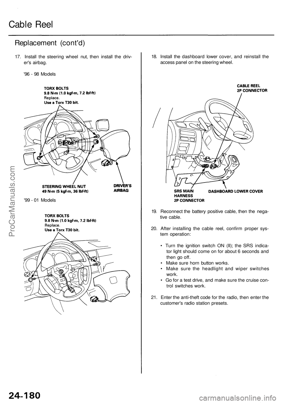
Replacement (cont'd )
17. Instal l th e steerin g whee l nut , the n instal l th e driv -
er' s airbag .
'9 6 - 9 8 Model s
Cable Ree l
18. Instal l th e dashboar d lowe r cover , an d reinstal l th e
acces s pane l o n th e steerin g wheel .
19 . Reconnec t th e batter y positiv e cable , the n th e nega -
tiv e cable .
20 . Afte r installin g th e cabl e reel , confir m prope r sys -
te m operation :
• Tur n th e ignitio n switc h O N (II) ; th e SR S indica -
to r ligh t shoul d com e o n fo r abou t 6 second s an d
the n g o off .
• Mak e sur e hor n butto n works .
• Mak e sur e th e headligh t an d wipe r switche s
work .
• G o fo r a tes t drive , an d mak e sur e th e cruis e con -
tro l switche s work .
21 . Ente r th e anti-thef t cod e fo r th e radio , the n ente r th e
customer' s radi o statio n presets .
'9
9 - 0 1 Model s
ProCarManuals.com
Page 1953 of 1954
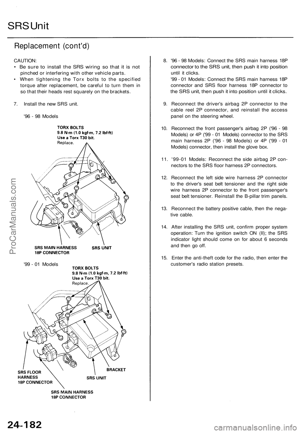
Replacement (cont'd )
CAUTION :
• B e sur e t o instal l th e SR S wirin g s o tha t i t i s no t
pinche d o r interferin g wit h othe r vehicl e parts .
• Whe n tightenin g th e Tor x bolt s t o th e specifie d
torqu e afte r replacement , b e carefu l t o tur n the m in
s o tha t thei r head s res t squarel y o n th e brackets .
7 . Instal l th e ne w SR S unit .
'9 6 - 9 8 Model s
SRS Uni t
8. '9 6 - 9 8 Models : Connec t th e SR S mai n harnes s 18 P
connecto r t o th e SR S unit , the n pus h it int o positio n
until i t clicks .
'9 9 - 0 1 Models : Connec t th e SR S mai n harnes s 18 P
connecto r an d SR S floo r harnes s 18 P connecto r t o
th e SR S unit , the n pus h it int o positio n unti l i t clicks .
9. Reconnec t th e driver' s airba g 2 P connecto r t o th e
cabl e ree l 2 P connector , an d reinstal l th e acces s
pane l o n th e steerin g wheel .
10 . Reconnec t th e fron t passenger' s airba g 2 P ('9 6 - 9 8
Models ) o r 4 P ('9 9 - 0 1 Models ) connecto r t o th e SR S
mai n harnes s 2 P ('9 6 - 9 8 Models ) o r 4 P ('9 9 - 0 1
Models ) connector , the n instal l th e glov e box .
11 . '99-0 1 Models : Reconnec t th e sid e airba g 2 P con -
nector s t o th e SR S floo r harnes s 2 P connectors .
12 . Reconnec t th e lef t sid e wir e harnes s 2 P connecto r
t o th e driver' s sea t bel t tensione r an d th e righ t sid e
wir e harnes s 2 P connecto r t o th e fron t passenger' s
sea t bel t tensioner . Reinstal l th e B-pilla r tri m panels .
13 . Reconnec t th e batter y positiv e cable , the n th e nega -
tiv e cable .
14 . Afte r installin g th e SR S unit , confir m prope r syste m
operation : Tur n th e ignitio n switc h O N (II) ; th e SR S
indicato r ligh t shoul d com e o n fo r abou t 6 second s
an d the n g o off .
15 . Ente r th e anti-thef t cod e fo r th e radio , the n ente r th e
customer' s radi o statio n presets .
'9 9 - 0 1 Model s
ProCarManuals.com
Page 1954 of 1954
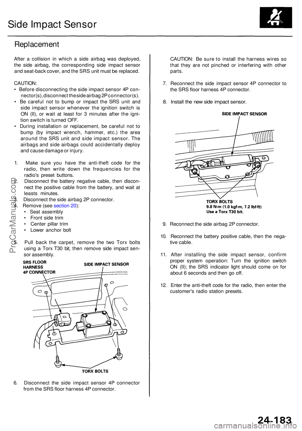
6. Disconnec t th e sid e impac t senso r 4 P connecto r
fro m th e SR S floo r harnes s 4 P connector .
Replacemen t
After a collisio n i n whic h a sid e airba g wa s deployed ,
th e sid e airbag , th e correspondin g sid e impac t senso r
an d seat-bac k cover , an d th e SR S uni t mus t b e replaced .
CAUTION :
• Befor e disconnectin g th e sid e impac t senso r 4 P con -
nector(s) , disconnec t th e sid e airba g 2 P connector(s) .
• B e carefu l no t t o bum p o r impac t th e SR S uni t an d
sid e impac t senso r wheneve r th e ignitio n switc h i s
O N (II) , o r wai t a t leas t fo r 3 minute s afte r th e igni -
tio n switc h is turne d OFF .
• Durin g installatio n o r replacement , b e carefu l no t t o
bum p (b y impac t wrench , hammer , etc. ) th e are a
aroun d th e SR S uni t an d sid e impac t sensor . Th e
airbag s an d sid e airbag s coul d accidentall y deplo y
an d caus e damag e o r injury .
1 . Mak e sur e yo u hav e th e anti-thef t cod e fo r th e
radio , the n writ e dow n th e frequencie s fo r th e
radio' s prese t buttons .
2 . Disconnec t th e batter y negativ e cable , the n discon -
nec t th e positiv e cabl e fro m th e battery , an d wai t a t
least s minutes .
3 . Disconnec t th e sid e airba g 2 P connector .
4 . Remov e (se e sectio n 20 ):
• Sea t assembl y
• Fron t sid e tri m
• Cente r pilla r tri m
• Lowe r ancho r bol t
5 . Pul l bac k th e carpet , remov e th e tw o Tor x bolt s
usin g a Tor x T3 0 bit , the n remov e sid e impac t sen -
so r assembly .
Side Impac t Senso r
CAUTION : B e sur e t o instal l th e harnes s wire s s o
tha t the y ar e no t pinche d o r interferin g wit h othe r
parts.
7. Reconnec t th e sid e impac t senso r 4 P connecto r t o
th e SR S floo r harnes s 4 P connector .
8. Instal l th e ne w sid e impac t sensor .
9. Reconnec t th e sid e airba g 2 P connector .
10 . Reconnec t th e batter y positiv e cable , the n th e nega -
tiv e cable .
11 . Afte r installin g th e sid e impac t sensor , confir m
prope r syste m operation : Tur n th e ignitio n switc h
O N (II) ; th e SR S indicato r ligh t shoul d com e o n fo r
abou t 6 second s an d the n g o off .
12 . Ente r th e anti-thef t cod e fo r th e radio , the n ente r th e
customer' s radi o statio n presets .
ProCarManuals.com