1996 ACURA RL KA9 fuse
[x] Cancel search: fusePage 381 of 1954

Engine Moun t Contro l Syste m
Troubleshootin g Flowchar t
NOTE:
Check th e vacuu m hose s an d line s fo r damag e an d prope r connections .
Refe r t o th e Troubleshootin g Procedure s (se e sectio n 11 ).
Th e engin e vibrate s excessivel y
whe n idling .
Chec k Idl e Speed :
War m u p engin e t o norma l oper -
ating temperatur e (th e coolin gfan come s o n 2 times) .
I s th e idl e spee d les s tha n
70 0 rpm ? Adjus
t th e idl e spee d (se e
sectio n 11 ).
Chec k th e Engin e Moun t Contro l
System:1. Full y depres s th e brak e pedal .
2 . Wit h th e transmissio n i n gear ,
hav e a n assistan t disconnec t
and reconnec t th e IMRC /engine moun t contro l solenoi d
valv e assembl y 6 P connector .
I s ther e a noticeabl e chang e in
idl e smoothnes s whe n th e
IMRC/engin e moun t contro lsolenoi d valv e assembl y 6 P con -
necto r i s disconnected ? Reconnec
t th e IMRC/engin e
moun t contro l solenoi d valv e
assembl y 6 P connector . Th e
engin e moun t contro l syste m isOK .
IMRC/ENGIN E MOUN T
CONTRO L SOLENOI D
VALV E ASSEMBL Y 6P
CONNECTO R
Test th e Engin e Moun t Contro l
Solenoi d Valv e Wire :
1. Shif t t o o r position .
2 . Disconnec t th e IMRC/engin e
moun t contro l solenoi d valv e
assembl y 6 P connector .
3 . Measur e voltag e betwee n th e
No. 3 termina l an d bod y
ground .
Is ther e batter y voltage ? Repai
r ope n i n BLK/YE L wir e
betwee n th e IMRC/engin e
moun t contro l solenoi d valv e
assembl y 6 P connecto r an d PC M
fuse (2 0 A) .
Wir e sid e o f femal e
terminal s
Tes t th e Engin e Moun t Contro l
Solenoi d Valv e Wire :
Measur e voltag e betwee n th e
No . 3 an d No . 6 terminals .
I s ther e batter y voltage ?
NO
(T o pag e 5-21 ) —
Repai r ope n i n L T GR N wir e
betwee n PC M (A17 ) an d th e
IMRC/engin e moun t contro l
solenoi d valv e assembl y 6 P
connector .— If th e wir e i s OK , substitut e a
known-goo d PC M an d recheck .
ProCarManuals.com
Page 402 of 1954

12. Remov e th e vacuu m hoses , the n remov e th e clam p
fro m th e under-hoo d fuse/rela y bo x (se e pag e 5-5 ).
13 . Remov e th e batter y cable s fro m th e under-hoo d
fuse/rela y box , the n remov e th e under-hoo d fuse /
rela y box .
UNDER-HOO DFUSE/RELAYBOX
14. Reliev e fue l pressur e b y loosenin g th e servic e bol t
o n th e fue l filte r abou t on e tur n (se e sectio n 11 ).
D o no t smok e whil e workin g o n th efue l system . Kee p ope n flam e an d spark s awa y fro m
th e wor k area . Drai n fue l onl y int o a n approve d
container.
15. Remov e th e fue l fee d hos e an d fue l retur n hose .
FUEL RETUR NHOSEFUEL FEE D
HOS E
FUE L PULSATIO N
DAMPE R
2 2 N- m (2. 2 kgf-m , 1 6 Ibf-ft )
WASHER SReplace.
16. Remov e th e evaporativ e emissio n (EVAP ) caniste r
hos e an d brak e booste r vacuu m hose .
BRAK E BOOSTE RVACUUM HOS E
EVA P CONTRO L
CANISTE R HOS E
17. Disconnec t th e connector , the n remov e th e contro l
box.
6 x 1. 0 m m12 N- m (1. 2 kgf-m ,
8. 7 Ibf-ft )
CONNECTO R CONTRO
L
BOX
BATTER YCABLE
BATTER YCABLE6 x 1. 0 m m12 N- m (1. 2 kgf-m ,8.7 Ibf-ft )
ProCarManuals.com
Page 500 of 1954

Engine Coolan t Temperatur e (ECT ) Gaug e
Gauge Testin g
1. Chec k th e No . 2 0 (2 0 A ) fus e in th e under-das h fuse /
rela y bo x befor e testing .
2 . Remov e th e engin e cove r (se e pag e 5-3 ).
3 . Mak e sur e th e ignitio n switc h i s OFF , the n discon -
nec t th e YEL/GR N wir e fro m th e EC T sendin g unit ,
and groun d it wit h a jumpe r wire .
ECT SENDIN GUNIT
YEL/GR NWIRE
4. Tur n th e ignitio n switc h O N (II) . Chec k tha t th e
pointe r o f th e EC T gaug e start s movin g towar d th e
"H " mark .
CAUTION : Tur n th e ignitio n switc h OF F befor e th e
pointe r reache s "H " o n th e gaug e dial . Failur e to d o
s o ma y damag e th e gauge .
If th e pointe r o f th e gaug e doe s no t mov e a t all ,
chec k fo r a n ope n in th e YEL/GR N wire .
I f th e wire s ar e OK , replac e th e EC T gauge .
I f th e EC T gaug e works , tes t th e EC T sendin g
unit.
ECT Sendin g Uni t Testin g
1. Remov e th e engin e cove r (se e pag e 5-3 ).
2 . Disconnec t th e YEL/GR N wir e fro m th e EC T sendin g
unit.
YEL/GR N WIR E(Covere d wit hinsulation )POSITIVETERMINA L
ECT SENDIN GUNIT
3. Usin g a n ohmmeter , measur e th e chang e i n resis -
tanc e betwee n th e positiv e termina l an d th e engin e
(ground ) wit h th e engin e col d an d wit h th e engin e
a t operatin g temperature .
Temperature
Resistance ( )
122°F(50°C )
226
239°F(115°C )
26.4
4. I f th e obtaine d reading s ar e substantiall y differen t
fro m th e specification s above , inspec t th e coolan t
leve l an d th e coolin g system . I f th e coolin g syste m
i s OK , replac e th e sendin g unit .
ProCarManuals.com
Page 513 of 1954
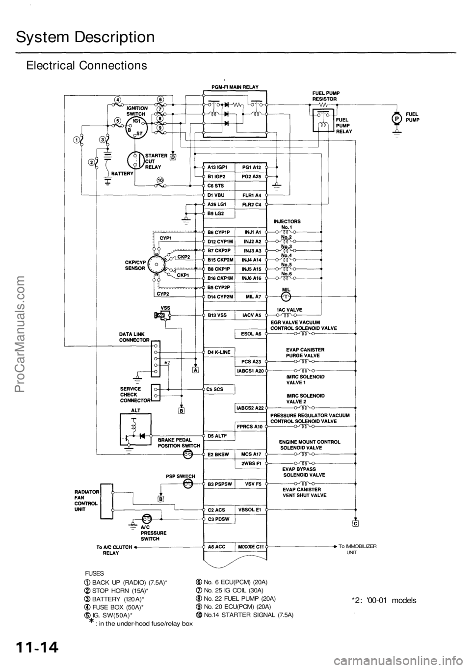
System Descriptio n
Electrical Connection s
FUSES
BACK U P (RADIO ) (7.5A) *
STO P HOR N (15A) *
BATTER Y (12 0 A) *
FUS E BO X (50A) *
IG . SW(50A) *
: i n th e under-hoo d fuse/rela y bo x
No. 6 ECU(PCM ) (20A )
No . 2 5 IG COI L (30A )
No . 2 2 FUE L PUM P (20A )
No . 2 0 ECU(PCM ) (20A )
No.1 4 STARTE R SIGNA L (7.5A )
*2: '00-0 1 model s
To IMMOBILIZE RUNIT
ProCarManuals.com
Page 540 of 1954

II. Powertrai n Contro l Modul e (PCM ) Rese t Procedur e
NOTE : Th e PC M memor y settin g is neede d afte r resettin g th e PC M (se e pag e 11-125 ).
Eithe r o f th e followin g action s wil l rese t th e PCM .
• Us e th e OB D II sca n too l o r Hond a PG M Teste r t o clea r th e PCM' s memory .
NOTE : Se e th e OB D II sca n too l o r Hond a PG M Teste r user' s manual s fo r specifi c operatin g instructions .
• Tur n th e ignitio n switc h OFF . Remov e th e BAC K U P RADI O (7. 5 A ) fus e fro m th e under-hoo d fuse/rela y bo x fo r
1 0 seconds .
NOTE : I f th e BAC K U P RADI O (7. 5 A ) fus e i s remove d an d th e ignitio n switc h O N (II) , MI L wil l repor t o n an d
BAC K U P RADI O
(7. 5 A ) FUS EPCM wil l stor e th e DT C P0560 .
UNDER-HOO DFUSE/RELA YBOX
III. Fina l Procedur e (thi s procedur e mus t b e don e afte r an y troubleshooting )
1 . Remov e th e SC S servic e connecto r i f i t i s connected .
NOTE : I f th e SC S servic e connecto r i s connecte d an d ther e ar e n o DTC s store d i n th e PCM , th e MI L wil l sta y
on whe n th e ignitio n switc h is turne d O N (II) .
2. D o th e PC M Rese t Procedure .
3 . Tur n th e ignitio n switc h OFF .
4 . Disconnec t th e OB D II sca n too l o r Hond a PG M Teste r fro m th e Dat a Lin k Connector .
ProCarManuals.com
Page 562 of 1954

MIL Circui t Troubleshootin g
Turn th e ignitio n switc h O N (II )
an d watc h th e Malfunctio n
Indicato r Lam p (MIL) . NOTE
:
I f thi s sympto m is intermittent , chec k fo r th e followin g problems .
• Th e MI L neve r come s o n afte r th e ignitio n switc h is turne d O N (II) .
— A loos e No . 6 EC U (PCM ) (2 0 A ) fus e in th e under-das h fuse/rela y bo x
— A loos e No . 2 2 FUE L PUM P (2 0 A ) fus e in th e under-das h fuse/rela y bo x
— A n intermitten t shor t i n th e wir e betwee n th e PC M (A7 ) an d th e gaug e assembl y
— A n intermitten t shor t i n th e wir e betwee n th e PC M (D10 ) an d th e MA P senso r
— A n intermitten t shor t i n th e wir e betwee n th e PC M (D21 ) an d th e T P sensor , EG R
valv e positio n sensor , fue l tan k pressur e sensor , TC S contro l valv e angl e senso r (wit h
TCS , VSA* )— A loos e No . 2 5 IG COI L (3 0 A ) fus e in th e under-das h fuse/rela y bo x
— PGM-F I mai n rela y
• Th e MI L stay s o n o r come s o n afte r 2 second s wit h th e ignitio n switc h turne d O N (II) .
— A n intermitten t shor t i n th e wir e betwee n th e PC M (C5 ) an d th e servic e chec k con -
nector , dat a lin k connector *
— A n intermitten t ope n in th e wire s betwee n th e PC M (D22 ) an d th e servic e chec k connec -
tor— A n intermitten t shor t i n th e wir e betwee n th e PC M (A7 ) an d th e gaug e assembly .
• Se e th e OBDI I sca n too l o r Hond a PG M Teste r user' s manual s fo r specifi c operatin g
instructions .
Doe s th e MI L com e o n an d
sta y on ?
YE S
(To pag e 11-66 )
Doe s th e lo w oi l pressur e
indicato r ligh t com e on ?
NO
YE S
Repai r shor t o r ope n i n th e
wir e betwee n No . 2 0 EC U
(PCM ) (2 0 A ) fus e an d gaug e
assembly .Replace No . 2 0 EC U (PCM ) (2 0A) fuse .
Check th e engin e starting :
Tr y t o star t th e engine .
Doe s th e engin e start ?
YES
(To pag e 11-68 )
* : '0 0 - 0 1 model s
(T
o pag e 11-64 )
NO
Chec k th e fuse :1. Tur n th e ignitio n switc h OFF .
2 . Tur n th e ignitio n switc h O N (II) . *
: '0 0 - 0 1 model s
ProCarManuals.com
Page 563 of 1954

PGM-FI Syste m
MIL Circui t Troubleshootin g (cont'd )
(From pag e 11-63 )
I s th e fus e OK ?
NO
Is th e fus e OK ?
YES
Chec k fo r a n ope n i n th e wire s
(IG P lines) :
1 . Disconnec t th e fue l injecto r
an d IA C valv e connectors .
2 . Tur n th e ignitio n switc h O N (II) .
3 . Measur e voltag e betwee n
bod y groun d an d th e PC M
connecto r terminal s A1 3 an d
B1 individually .
Is ther e batter y voltage ?NO
YE S
— Repai r shor t i n th e wir e
betwee n No . 6 EC U (PCM ) (2 0
A ) fus e an d PGM-F I mai n
relay.— Repai r shor t i n th e wir e
betwee n PGM-F I mai n rela y
an d th e PCM , fue l injectors ,
o r IA C valve .
— Repai r shor t i n th e wir e
betwee n fue l injector s an d
IA C valve .
— Replac e No . 6 EC U (PCM ) (2 0
A) fuse .
— Repai r shor t i n th e wir e
betwee n No . 2 5 IG COI L (3 0 A )
fus e an d PGM-F I mai n relay .
— Replac e No . 2 5 IG COI L (3 0 A )
fuse .PCM CONNECTOR SA (26P)
— Repai r ope n i n th e wire(s )
betwee n th e PC M (A13 , B9 )
an d PGM-F I mai n relay .
— Chec k fo r a poo r connectio n
o r loos e wire s a t th e PGM-F I
mai n relay .
— Tes t th e PGM-F I mai n rela y
(se e pag e 11-146 ).
— Repai r shor t o r ope n i n th e
wir e betwee n th e immobilize r
uni t an d PCM . Wir
e sid e o f femal e terminal s
(T o pag e 11-65 )
NO
YE S
ProCarManuals.com
Page 591 of 1954

PGM-FI Syste m
Heated Oxyge n Senso r (HO2S ) Heate r (cont'd )
(From pag e 11-91 ) RIGH
T PRIMAR Y HO2 S (Ban k 1 , Senso r 1 ) CONNECTO R (C119) ,
LEF T PRIMAR Y HO2 S (Ban k 2 , Senso r 1 ) CONNECTO R (C126)*2
SECONDAR Y HO2 S (Senso r 2 ) CONNECTO R (C610)*1
Chec k fo r a n ope n i n th e wir e
(IG 1 line) :
Measur e voltag e betwee n No . 3
termina l an d bod y ground .
I s ther e batter y voltage ?
YES
Chec k fo r a n ope n i n th e wir e
(O2HT C line) :
1 . Tur n th e ignitio n switc h OFF .
2 . Reconnec t th e HO2 S connec -
tor.3. Disconnec t th e PC M connecto rA (26P) .4. Tur n th e ignitio n switc h O N (II) .
5 . Measur e voltag e betwee n th e
PC M connecto r terminal s A19 ,
A21*l or A18 * an d A12 .
Is ther e 0. 1 V or less ?
NO
Substitut e a known-goo d PC M
an d rechec k (se e pag e 11-42 fo r
immobilize r information) . I f symp -
tom/indicatio n goe s away , replac e
th e origina l PCM .
(Fro m pag e 11-91 )
Chec k fo r a shor t i n th e wir e
(O2SHT C line) :1. Tur n th e ignitio n switc h OFF .
2 . Disconnec t th e PC M connec -
tor A (26P) .3. Chec k fo r continuit y betwee n
th e PC M connecto r A19 , A21* '
o r A18*
2 termina l an d bod y
ground .
I s ther e continuity ?
NO
Substitut e a known-goo d PC M
an d rechec k (se e pag e 11-4 1 fo r
immobilize r information) . I f symp -
tom/indicatio n goe s away , replac e
th e origina l PCM .
*1: P014 1*2: P015 5
NO
Repai r ope n in th e wir e betwee nfuse No . 2 0 EC U (PCM ) (2 0 A ) i nth e under-das h fuse/rela y bo x an d
righ t primar y HO2 S (Ban k 1 ,
Senso r 1) , secondar y HO2 S (Sen -
so r 2)*
1 o r lef t primar y HO2 S(Bank 2 , Senso r 1)*2.
Wir e sid e o f femal e terminal s
PC M CONNECTO R A (26P )
Repai r ope n in th e wir e betwee n
PC M (A19 , A21*
1 o r A18*2) an dHO2S .
Wire sid e o f femal e terminal s
Repai r shor t i n th e wir e betwee n
PC M (A19 , A21*
1 o r A18*2) an dHO2S .
YES
YES
ProCarManuals.com