1996 ACURA RL KA9 fuse
[x] Cancel search: fusePage 229 of 1954

Navigation Syste m
Genera l Troubleshootin g Informatio n
General Operatio n
Refer t o th e Acur a Navigatio n Syste m Owner' s manua l
fo r th e navigatio n syste m operatin g procedures .
Anti-theft Featur e
The navigatio n syste m ha s a code d thef t protectio n cir -
cuit . B e sur e t o ge t th e customer' s 4-digi t securit y cod e
numbe r before :
• disconnectin g th e batter y
• disconnectin g th e navigatio n uni t 8 P connecto r
• removin g th e No . 5 6 (7.5A ) fus e fro m th e under-hoo d
fuse/rela y bo x
Afte r service , reconnec t powe r t o th e navigatio n unit ,
an d tur n th e ignitio n switc h O N (II) . Ente r th e 4-digi t
securit y code , the n selec t "Done" .
I f th e cod e canno t b e found , us e th e interactiv e Networ k
( iN ) t o loo k i t up . Yo u wil l nee d th e seria l numbe r fo r
th e navigatio n uni t i n th e trunk . I t i s o n a ta g o n th e
undersid e o f th e unit . Alternatively , yo u ca n vie w th e
seria l numbe r i n on e o f th e Nav i EC U diagnosti c
screens.
When replacin g th e navigatio n unit , b e sur e t o giv e th e
custome r th e ne w anti-thef t securit y code .
Sympto m Diagnosi s
Under som e circumstances , th e navigatio n syste m ma y
behav e in a n inconsisten t manner . Som e customer s ma y
thin k tha t thi s indicate s a proble m when , i n fact , th e
syste m is workin g properly . Kee p th e followin g item s i n
min d whe n interviewin g customer s abou t symptom s
o f th e navigatio n system .
Self-lnertia l Navigatio n Limitation s
When GP S signal s canno t b e receive d (lik e in a tunne l o r
i n a n urba n environmen t o f tal l buildings) , th e syste m is
totall y dependan t o n th e ya w rat e an d spee d senso r t o
positio n th e vehicl e o h th e map . Unde r thes e circum -
stance s smal l error s i n th e ya w rat e an d spee d senso r
ca n accumulat e an d displa y th e vehicl e positio n o n a n
adjacen t street , o r laggin g behin d th e actua l position .
Thi s i s normal , an d usuall y correct s itsel f onc e sate -
llit e receptio n is re-established .
Th e followin g circumstance s ma y cause s vehicl e posi -
tionin g errors . •
Movin g th e vehicl e wit h th e navigatio n syste m o n an d
th e vehicl e stopped , suc h a s b y ferr y o r to w truck , o r i f
th e vehicl e is spu n o n a tur n tabl e
• Tir e slippage , change s i n tir e rollin g diameters , an d
som e drivin g situation s ma y caus e discrepancie s i n
trave l distances . Example s o f thi s include :
- Continuou s tir e slippag e o n a slipper y surfac e
- Drivin g wit h sno w chain s mounte d
-Abnorma l tir e pressur e
- Incorrec t tir e siz e
- Frequen t lan e change s acros s a wid e highwa y
-Continuou s drivin g o n a straigh t o r gentl y curvin g
highwa y
• Tolerance s i n th e syste m an d ma p inaccuracie s some -
times limi t ho w precisel y th e vehicl e positio n i s indi -
cated . Example s o f thi s include :
- Drivin g o n road s no t show n o n th e ma p (ma p match -
in g i s no t possible )
- Drivin g o n a roa d tha t wind s i n on e direction , suc h a s
a loo p bridge , a n interchange , o r a spira l parkin g
garage
-Drivin g o n a roa d wit h a serie s o f shar p hair-pi n
turn s
- Drivin g nea r a gradua l highwa y exi t o r transitio n
- Drivin g o n on e o f tw o close paralle l road s
- Makin g man y 9 0 degre e turn s
Globa l Positionin g Syste m (GPS ) Limitation s
The GP S canno t detec t th e vehicle' s positio n durin g th e
followin g instances :
• Fo r th e firs t 5 to 1 0 minute s afte r reconnectin g th e bat -
ter y (thi s ca n tak e a s lon g a s 4 5 minutes )
• Whe n th e satellit e signal s ar e blocke d b y tal l building ,
mountains , tunnels , larg e trees , o r larg e truck s
• Whe n ther e i s n o satellit e signa l outpu t (Signa l outpu t
i s sometime s stoppe d fo r satellit e servicing )
• Whe n th e satellit e signal s ar e blocke d b y th e operatio n
of som e electroni c aftermarke t accessorie s including ,
but no t limite d t o non-DE M in-das h entertainmen t
unit s (radio , C D players/changers , an d L o Jack ) an d
windo w tintin g abov e th e GP S antenn a
Th e accurac y o f GP S is reduce d durin g thes e instances :
• Whe n onl y tw o satellit e signal s ca n b e receive d (Thre e
satellit e signal s ar e require d fo r accurat e positioning )
• Whe n th e satellit e contro l center s ar e experiencin g
problem s
• Whe n drivin g hea r hig h tensio n powe r lines .
• Whe n drivin g nea r tal l building s tha t reflec t satellit e
signals , creatin g fals e positio n locatio n readings .
• I f electroni c GP S jammin g i s occurrin g eithe r inten -
tionally , o r unintentionally .
• I f loos e item s o r pet s ar e restin g abov e th e antenn a
o n th e rea r shelf .
ProCarManuals.com
Page 249 of 1954

Symptom Troubleshootin g
No pictur e is displaye d
Diagnosti c Test : Navigatio n Syste m Lin k
1 . Chec k th e No . 5 6 (7.5A ) fus e in th e under-hoo d fuse /
rela y bo x an d No . 4 (10A ) fus e in th e under-das h fuse /
relay box , an d reinstal l th e fuse s i f the y are-OK .
Are the fuses OK?
YES—G o to ste p 2 .
NO—Replac e th e fus e an d recheck .
2 . Tur n th e ignitio n switc h t o AC C (I) .
3 . Operat e th e radi o an d liste n t o th e audio .
Can audio be heard?
YES—G o to ste p 4 .
NO—Chec k th e AC C circuit .
4 . Tur n th e ignitio n switc h O N (II) .
5 . Measur e th e voltag e betwee n bod y groun d an d navi -
gatio n uni t connecto r C (8P ) terminal s No . 1 an d No .
2 individually .
Wire sid e o f femal e terminal s
Is there battery voltage?
YES—G o to ste p 6 .
NO—I f th e + B wir e doe s no t hav e voltage , repai r
ope n in th e wir e betwee n th e under-hoo d fus e rela y
bo x an d th e navigatio n unit .
I f th e AC C wir e doe s no t hav e voltage , repai r ope n in
th e wir e betwee n th e under-das h fus e rela y bo x an d
th e navigatio n unit . 6
. Chec k fo r continuit y betwee n navigatio n uni t connec -
to r C (8P ) termina l No . 4 an d bod y ground .
NAVIGATIO N UNI T CONNECTO R C (8P )
Wire sid e o f femal e terminal s
Is there continuity?
YES—G o to ste p 7 .
NO—Repai r ope n i n th e wir e betwee n th e navigatio n
unit an d bod y groun d (G603) .
7 . Tur n th e ignitio n switc h OFF .
8 . Perfor m th e force d startin g o f th e displa y (se e pag e
23-52 )
Is the diagnosis menu of the picture diagnosis dis-
played?
YES—G o int o th e Diagnosti c mod e an d us e th e "Nav i
Syste m Link " diagnosti c (se e pag e 23-40 ) t o chec k
the links .
NO—G o to ste p 9 .
9 . Shiel d th e displa y uni t fro m th e su n wit h you r hand ,
an d chec k tha t th e displa y i s blac k (onl y bac k ligh t i s
ON) .
Can you see the back light?
YES—Replac e th e navigatio n uni t
(see pag e 23-53 ).
NO—Replac e th e displa y uni t (se e pag e 23-53 ).
ProCarManuals.com
Page 254 of 1954

Navigation Syste m
Sympto m Troubleshootin g (cont'd )
Display uni t button s d o no t wor k
NOTE :
• Alway s chec k th e connector s fo r poo r connection s o r
loos e terminals .
• Befor e troubleshooting , ge t th e navigatio n syste m
anti-thef t codes .
• Afte r troubleshooting , ente r th e navigatio n syste m
anti-thef t codes .
1. Tur n th e ignitio n switc h to AC C (I) .
2. G o int o th e Diagnosti c mod e an d us e "Touc h Panel "
diagnosti c unde r Monito r Chec k (se e pag e 23-41 )
and, i f necessary , "Display " diagnosti c unde r Uni t
Chec k (se e pag e 23-43 ).
Do the buttons work properly?
YES—System is OK .
NO—G o t o ste p 3 .
3. Measur e th e voltag e betwee n bod y groun d an d dis -
play uni t connecto r B (20P ) termina l No . 1 an d No . 2
individually .
DISPLAY UNI T CONNECTO R B (20P )
+B(WHT/YEL ) AC C (WHT/YEL )
Wire sid e o f femal e terminal s
Is there battery voltage?
YES—G o to ste p 4 .
NO—I f th e + B wir e doe s no t hav e voltage , repai r th e
ope n in th e wir e betwee n th e under-hoo d fuse/rela y
box an d th e displa y unit . I f th e AC C wir e doe s no t
hav e voltage , repai r th e ope n in th e wir e betwee n th e
under-das h fuse/rela y bo x an d th e displa y unit .
ProCarManuals.com
Page 324 of 1954

Starting Syste m
Componen t Locatio n Inde x
STARTE R CU T RELA YWire colors : BLK/WHT ,
BLK/WHT , BLK/WH T an d WHT/RE D
UNDER-DAS HFUSE/RELAY BO X
STARTE RTest, pag e 4- 5
Replacement , pag e 4- 6
Overhaul , pag e 4- 8
Solenoi d Test , pag e 4- 9Reassembly , pag e 4-1 4
ProCarManuals.com
Page 340 of 1954
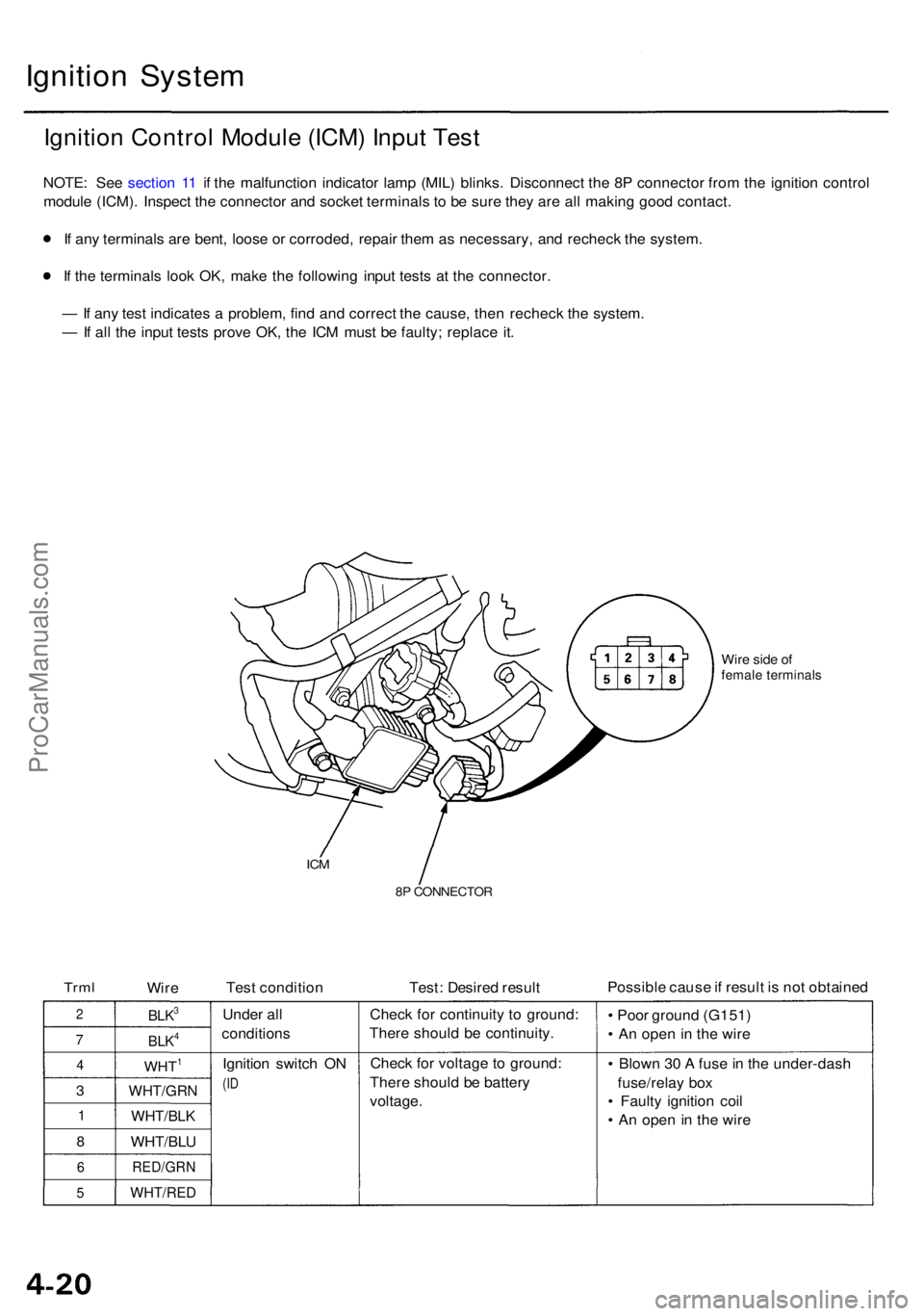
Ignition Syste m
Ignition Contro l Modul e (ICM ) Inpu t Tes t
NOTE : Se e sectio n 1 1 i f th e malfunctio n indicator lamp (MIL ) blinks . Disconnec t th e 8 P connecto r fro m th e ignitio n contro l
modul e (ICM) . Inspec t th e connecto r an d socke t terminal s t o b e sur e the y ar e al l makin g goo d contact .
I f an y terminal s ar e bent , loos e o r corroded , repai r the m a s necessary , an d rechec k th e system .
I f th e terminal s loo k OK , mak e th e followin g inpu t test s a t th e connector .
— If an y tes t indicate s a problem , fin d an d correc t th e cause , the n rechec k th e system .
— If al l th e inpu t test s prov e OK , th e IC M mus t b e faulty ; replac e it .
Wir e sid e o ffemal e terminal s
ICM
8P CONNECTO R
TrmlWire Tes
t conditio n Test: Desire d resul t Possibl
e caus e if resul t i s no t obtaine d
2
7
4
3
1
8
6
5
BLK3
BLK4
WHT1
WHT/GR N
WHT/BLK
WHT/BLU
RED/GR N
WHT/RED
Under al l
condition s
Ignitio n switc h O N
(ID
Chec k fo r continuit y t o ground :
Ther e shoul d b e continuity .
Chec k fo r voltag e t o ground :
Ther e shoul d b e batter y
voltage . •
Poo r groun d (G151 )
• A n ope n in th e wir e
• Blow n 3 0 A fus e in th e under-das h
fuse/rela y bo x
• Fault y ignitio n coi l
• A n ope n i n th e wir e
ProCarManuals.com
Page 344 of 1954

Troubleshooting
If th e chargin g syste m ligh t doe s no t com e o n o r doe s no t g o off , o r th e batter y i s dea d o r low , tes t th e followin g item s i n
th e orde r liste d below :
1. Batter y (se e sectio n 23 )
2. Chargin g Syste m Ligh t (se e below )
3. Alternator/Regulato r (se e pag e 4-27 )
Chargin g Syste m Ligh t Tes t
Chec k th e No . 2 0 (7. 5 A ) fus e i n
th e under-das h fuse/rela y box .
I s th e fus e OK ?
Chec k fo r a n ope n in th e L circuit :
1 . Disconnec t th e 4 P connecto r
fro m th e alternator .
2 . Groun d th e No . 3 termina l o f
th e 4 P connector .
3 . Tur n th e ignitio n switc h O N (II) .
Doe s th e chargin g syste m
ligh t com e on ?
Disconnec t th e No . 3 termina l
o f th e 4 P connecto r fro m th e
ground .
Doe s th e chargin g syste m
ligh t g o off ?
Chec k fo r a shor t t o bod y groun d
i n th e L circuit :
1 . Tur n th e ignitio n switc h OFF .
2 . Disconnec t th e AB S contro l
uni t (C447 ) an d passenger' s
multiple x contro l uni t (C401) ,
a s applicable .
3. Tur n th e ignitio n switc h O N (II) .
Doe s th e chargin g syste m
ligh t sta y off ?
Chec k fo r shor t i n contro l unit(s) :
1 . Tur n th e ignitio n switc h OFF .
2 . Reconnec t th e AB S contro l
uni t connector .
3 . Tur n th e ignitio n switc h O N
(II) , an d chec k th e chargin g
system light .
Did th e ligh t sta y of f whe n yo u
turne d o n th e ignitio n switc h
afte r connectin g AB S contro l uni t
connector ?
Substitute a known-goo d AB S
contro l unit , an d recheck .
ALTERNATO R4P CONNECTO R
Replace th e fuse .
Chec k fo r a blow n chargin g sys -
te m ligh t bulb . I f th e bul b i s OK ,
repai r th e ope n i n th e WHT/BL U Wir
e sid e o f
femal e terminal s
(T o page 4-26)
Tur n th e ignitio n switc h OFF , an d
repai r th e shor t t o groun d in th e
WHT/BL U wire .
Substitut e a known-goo d pas -
senger' s multiple x contro l unit ,
and recheck .
ProCarManuals.com
Page 356 of 1954

Cruise Control
Control Unit Input Test (cont'd)
Cavity Wire
Test condition
Test: Desired result
Possible cause if result is not obtained
3
13
7
6
14
12
2
5
10
9
11
1
BLK
LT GRN
LT GRN/BLK
LT GRN/RED
PNK
BLU/WHT
GRY
GRN/WHT
BLU/YEL
BRN
BRN/BLK
BRN/WHT
Under all conditions
Ignition switch ON (II) and
main switch ON
Resume button pushed
Cancel button pushed
Set button pushed
Cancel button pushed
Shift lever in , or
Ignition switch ON (II), and
main switch ON; raise the
front of the vehicle, and rotate
one wheel slowly while
holding the other wheel.
Ignition switch ON (II), main
switch ON; brake pedal
pressed, then released
Brake pedal pressed then
released
Ignition switch ON (II)
Under all conditions
Under all conditions
Under all conditions
Check for continuity to ground:
There should be continuity.
Check for voltage to ground:
There should be battery voltage.
Check for voltage to ground:
There should be battery voltage.
When testing terminal No. 7, there
should be no voltage on terminal No. 6.
Check for voltage to ground:
There should be battery voltage.
When testing terminal No. 7, there
should be voltage on terminal No. 6.
Check for voltage to ground:
There should be battery voltage.
When testing terminal No. 6, there
should be no voltage on terminal No. 7.
Check for voltage to ground:
There should be battery voltage.
When testing terminal No. 6, there
should be voltage on terminal No. 7.
Check for continuity to ground:
There should be continuity.
NOTE: There should be no continuity
when the shift lever is in other positions.
Check for voltage between the
BLU/ WHT and BLK terminals:
There should be cycle 0 - 5 V or
battery voltage.
Check for voltage to ground:
There should be 0 V with the pedal
pressed, and battery voltage with
the pedal released.
Check for voltage to ground:
There should be battery voltage with
the pedal pressed, and 0 V with the
pedal released.
Attach to ground:
The cruise light in the gauge assembly
should come on.
Check for resistance to ground:
There should be 80 -120
Check for resistance to ground:
There should be 70 -110
Check for resistance to ground:
There should be 40 - 60
• Poor ground (G401, G402)
• An open in the wire
• Blown No. 20 (20 A) fuse in the
under-dash fuse/relay box
• Faulty main switch
• An open in the wire
• Blown No. 39 (15 A) fuse in the
under-hood fuse/relay box
• Faulty horn relay
• Faulty set/resume/cancel switch
• Faulty cable reel
• An open in the wire
• Short between LT GRN/BLK and
LT GRN/RED wires
• Blown No. 39 (15 A) fuse in the
under-hood fuse/relay box
• Faulty horn relay
• Faulty set/resume/cancel switch
• Faulty cable reel
• An open in the wire
• Blown No. 39 (15 A) fuse in the
under-hood fuse/relay box
• Faulty horn relay
• Faulty set/resume/cancel switch
• Faulty cable reel
• An open in the wire
• Short between LT GRN/BLK and
LT GRN/RED wires
• Blown No. 39 (15 A) fuse in the
under-hood fuse/relay box
• Faulty horn relay
• Faulty set/resume/cancel switch
• Faulty cable reel
• An open in the wire
• Faulty A/T gear position switch
• Poor ground (G401, G402)
• An open in the wire
• Faulty vehicle speed sensor (VSS)
• An open in the wire
• Short to ground
• Blown No. 39 (15 A) fuse in the
under-hood fuse/relay box
• Faulty brake switch
• An open in the wire
• Blown No. 39 (15 A) fuse in the
under-hood fuse/relay box
• Faulty brake switch
• An open in the wire
• Blown bulb
• Faulty gauge circuit
• An open in the wire
• Faulty actuator solenoid
• An open in the wireProCarManuals.com
Page 367 of 1954

12. Remov e th e vacuu m hose , the n remov e th e clam p
fro m th e under-hoo d fuse/rela y box .
VACUU MHOSE CLAM
P
13. Remov e th e alternato r an d batter y cable s fro m th e
under-hoo d fuse/rela y box , the n remov e th e under -
hoo d fuse/rela y box .
ALTERNATO RCABLE
6 x 1. 0 m m12 N- m (1. 2 kgf-m ,
8. 7 Ibf-ft )
BATTER YCABLE
UNDER-HOO DFUSE/RELAYBOX
14. Disconnec t th e engin e wir e harnes s connecto r o n
th e lef t sid e o f th e engin e compartment .
15 . Remov e th e connecto r an d engin e wir e harnes s
clamp .
CONNECTO R
ENGINE WIR E
HARNES S
CONNECTO R
CLAMP
6 x 1. 0 m m12 N- m (1. 2 kgf-m , 8. 7 Ibf-ft )
16. Reliev e fue l pressur e b y loosenin g th e servic e bol t
o n th e fue l filte r abou t on e tur n (se e sectio n 11 ).
D o no t smok e whil e workin g o n th e
fue l system . Kee p ope n flam e an d spark s awa y fro m
th e wor k area . Drai n fue l onl y int o a n approve d
container.
17. Remov e th e fue l fee d hos e an d fue l retur n hose .
SERVIC E BOL T
1 2 N- m (1. 2 kgf-m , 8. 7 Ibf-ft )
WASHE R
Replace .27 N- m (2. 8 kgf-m ,20 Ibf-ft )
WASHER S
Replace .
FUE L FEE D
HOS E
FUEL RETUR N
HOS E
ProCarManuals.com