Page 843 of 1954

Valve Bod y
Repai r
NOTE : Thi s repai r i s onl y necessar y i f on e o r mor e o f
th e valve s i n a valv e bod y d o no t slid e smoothl y i n thei r
bores . Yo u ma y us e thi s procedur e t o fre e th e valve s i n
th e valv e bodies .
1 . Soa k a shee t o f #60 0 abrasiv e pape r i n AT P fo r
abou t 3 0 minutes .
2 . Carefull y ta p th e valv e bod y s o th e stickin g valv e
drop s ou t o f it s bore .
CAUTION : I t ma y b e necessar y to us e a smal l screw -
drive r t o pr y th e valv e free . B e carefu l no t t o scratc h
th e bor e wit h th e screwdriver .
3 . Inspec t th e valv e fo r an y scuf f marks . Us e th e ATF -
soake d #60 0 pape r t o polis h of f an y burr s tha t ar e
o n th e valve , the n was h th e valv e in solven t an d dr y
it wit h compresse d air .
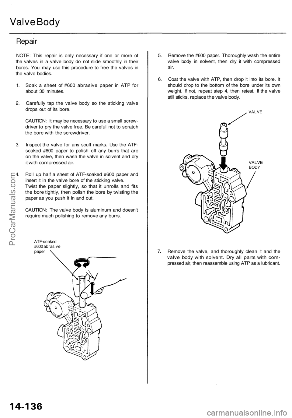
4. Rol l u p hal f a shee t o f ATF-soake d #60 0 pape r an d
inser t i t i n th e valv e bor e o f th e stickin g valve .
Twist th e pape r slightly , s o tha t i t unroll s an d fit s
the bor e tightly , the n polis h th e bor e b y twistin g th e
pape r a s yo u pus h i t i n an d out .
CAUTION : Th e valv e bod y is aluminu m an d doesn' t
requir e muc h polishin g to remov e an y burrs .
ATF-soake d#600 abrasiv epaper
5. Remov e th e #60 0 paper . Thoroughl y was h th e entir e
valv e bod y i n solvent , the n dr y i t wit h compresse d
air.
6. Coa t th e valv e wit h ATP , the n dro p it int o it s bore . I t
shoul d dro p t o th e botto m o f th e bor e unde r it s ow n
weight . I f not , repea t ste p 4 , the n retest . I f th e valv e
still sticks , replac e th e valv e body .
VALV E
VALVEBODY
Remov e th e valve , an d thoroughl y clea n i t an d th e
valv e bod y wit h solvent . Dr y al l part s wit h com -
presse d air , the n reassembl e usin g AT P a s a lubricant .
ProCarManuals.com
Page 1030 of 1954

Front Suspensio n
Knuckle/Hub Replacemen t
NOTE:
• Us e onl y genuin e Hond a whee l weight s fo r aluminu m wheels . Non-genuin e whee l weight s ma y corrod e an d damag e
aluminu m wheels .
• Befor e installin g th e wheel , clea n th e matin g surfac e o f th e brak e dis c an d insid e o f th e wheel .
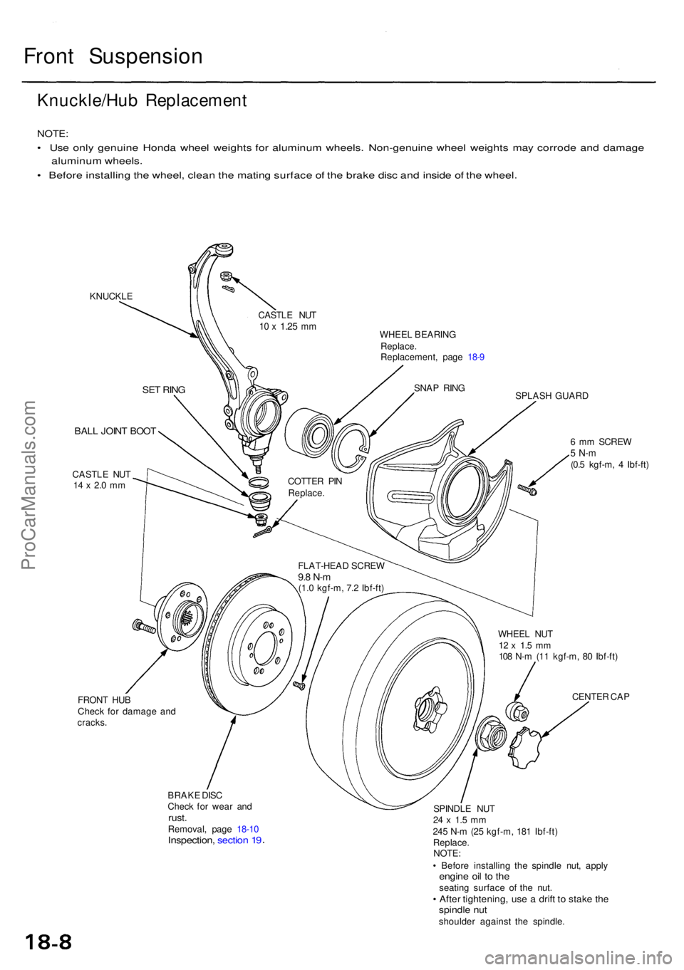
KNUCKL E
WHEEL BEARIN G
Replace .
Replacement , pag e 18- 9
SPLASH GUAR D
BALL JOIN T BOO T
CASTL E NU T14 x 2. 0 m m
FRON T HU B
Chec k fo r damag e an d
cracks .
BRAKE DIS C
Chec k fo r wea r an d
rust .Removal , pag e 18-1 0Inspection , sectio n 1 9
6 m m SCRE W5 N- m(0.5 kgf-m , 4 Ibf-ft )
WHEE L NU T
12 x 1. 5 m m108 N- m (1 1 kgf-m , 8 0 Ibf-ft )
CENTE R CA P
SPINDL E NU T
24 x 1. 5 m m245 N- m (2 5 kgf-m , 18 1 Ibf-ft )
Replace .
NOTE :
• Befor e installin g th e spindl e nut , appl y
engine oi l t o th eseatin g surfac e o f th e nut .• Afte r tightening , us e a drif t t o stak e th espindl e nu tshoulde r agains t th e spindle .
FLAT-HEA
D SCRE W
9.8 N- m(1.0 kgf-m , 7. 2 Ibf-ft )
COTTE
R PI N
Replace .
SNAP RIN G
CASTL
E NU T
10 x 1.2 5 mm
SE T RIN G
ProCarManuals.com
Page 1041 of 1954

Rear Suspensio n
Hub Bearin g Uni t Replacemen t
NOTE:
• Us e onl y genuin e Hond a whee l weight s fo r aluminu m wheels . Non-genuin e wheel s weight s ma y corrod e an d damag e
aluminum wheels .
• Befor e installin g th e wheel , clea n th e matin g surface s o f th e brak e dis c an d insid e o f th e wheel .
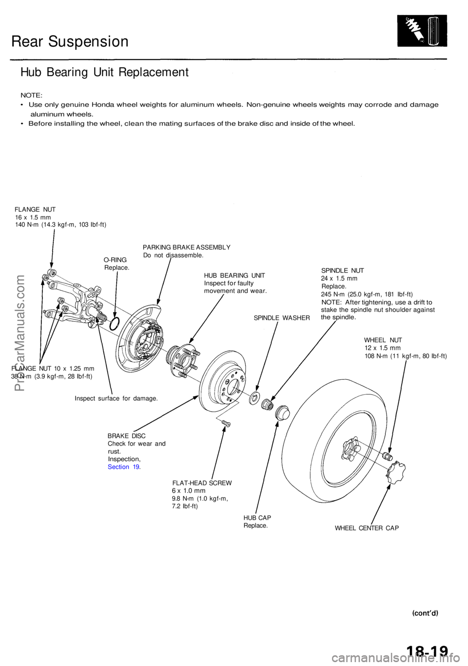
FLANG E NU T16 x 1. 5 m m140 N- m (14. 3 kgf-m , 10 3 Ibf-ft )
PARKING BRAK E ASSEMBL Y
D o no t disassemble .
HU B BEARIN G UNI T
Inspec t fo r fault ymovemen t an d wear .
SPINDL E WASHE R
SPINDLE NU T24 x 1. 5 m mReplace .245 N- m (25. 0 kgf-m , 18 1 Ibf-ft )NOTE : Afte r tightening , us e a drif t t ostak e th e spindl e nu t shoulde r agains tthe spindle .
WHEEL NU T12 x 1. 5 m m108 N- m (1 1 kgf-m , 8 0 Ibf-ft )
FLANG E NU T 1 0 x 1.2 5 m m
3 8 N- m (3. 9 kgf-m , 2 8 Ibf-ft )
BRAKE DIS C
Chec k fo r wea r an d
rust .Inspection ,Section 19 .
FLAT-HEAD SCRE W
6 x 1. 0 m m9.8 N- m (1. 0 kgf-m ,
7. 2 Ibf-ft )
HUB CA PReplace .
WHEEL CENTE R CA P
Inspec
t surfac e fo r damage .
O-RINGReplace .
ProCarManuals.com
Page 1047 of 1954
Installation
1. Lower the rear suspension, and set the damper
assembly in its original position.
2. Loosely install the damper mounting bolt.
3. Raise the rear suspension with a floor jack until the
weight of the vehicle is on the damper.
NOTE:
• The damper mounting bolts should be tightened
with the damper under vehicle load.
• Do not interchange the right and left dampers.
CAUTION: Carefully install the damper assembly
on the damper bracket making sure the speed sen-
sor wire does not get caught between the damper
and the bracket.
REAR
DAMPER
DAMPER MOUNTING
BOLT
103 N-m
(10.5 kgf-m, 76 Ibf-ft)
4. Install and tighten the damper mounting nuts.
5. Tighten the damper mounting bolt.
6. Install the damper cap and rear speaker.
DAMPER CAP
DAMPER
MOUNTING NUT
38 N-m
(3.9 kgf-m, 28 Ibf-ft)ProCarManuals.com
Page 1644 of 1954
Multiplex Contro l Syste m
Componen t Locatio n Inde x
IGNITIO N KE Y LIGH TReplacement , pag e 23-25 4
MULTIPLE X CONTRO L UNI T (PASSENGER'S )(Has built-i n th e beeper )
MULTIPLE X CONTRO L UNI T (DOOR )(built int o th e powe r windo wmaster switch )
MULTIPLE X CONTRO LINSPECTIO N CONNECTO R
[Wir e color : PNK/BL K an d BLK ]
MULTIPLE X CONTRO L UNI T (DRIVER'S )
Description
The multiple x contro l syste m is compose d o f thre e contro l unit s (locate d i n th e driver' s sid e kic k panel , passenger' s sid e
kic k panel , an d driver' s door) .
Thes e thre e contro l unit s sen d multiple x signal s ove r share d wires,reduc e th e numbe r o f contro l unit s an d wir e harnes s
weight , an d improve s th e qualit y o f electrica l function s b y mean s o f th e integrate d circuits . Thi s syste m ha s a built-i n self -
diagnosi s function .
ProCarManuals.com