1996 ACURA RL KA9 manual radio set
[x] Cancel search: manual radio setPage 358 of 1954
Cruise Control
Set/Resume/Cancel Switch Test/Replacement (cont'd)
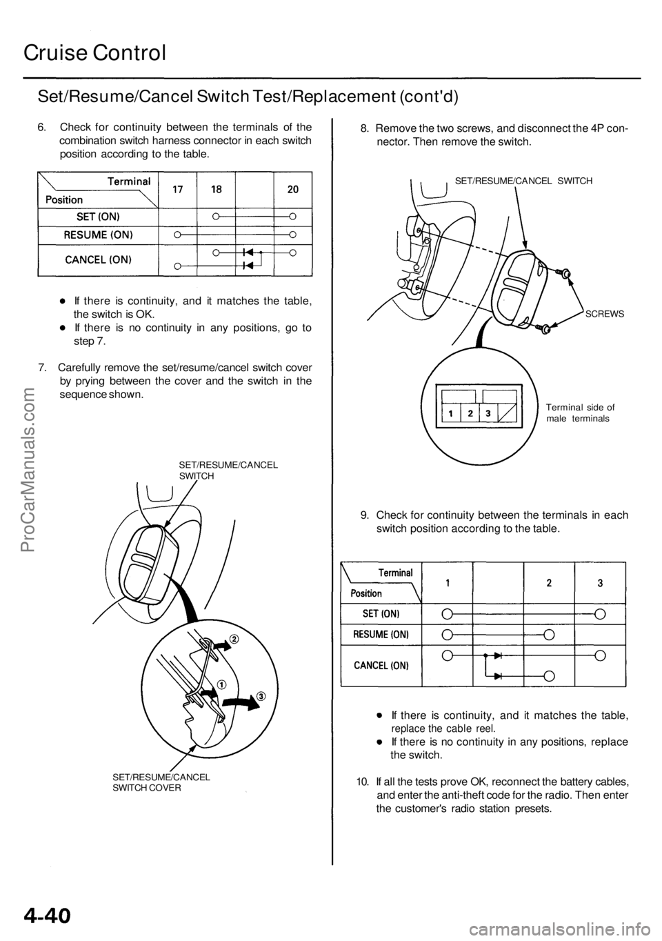
6. Check for continuity between the terminals of the
combination switch harness connector in each switch
position according to the table.
If there is continuity, and it matches the table,
the switch is OK.
If there is no continuity in any positions, go to
step 7.
7. Carefully remove the set/resume/cancel switch cover
by prying between the cover and the switch in the
sequence shown.
SET/RESUME/CANCEL
SWITCH
SET/RESUME/CANCEL
SWITCH COVER
8. Remove the two screws, and disconnect the 4P con-
nector. Then remove the switch.
SET/RESUME/CANCEL SWITCH
SCREWS
9. Check for continuity between the terminals in each
switch position according to the table.
If there is continuity, and it matches the table,
replace the cable reel.
If there is no continuity in any positions, replace
the switch.
10. If all the tests prove OK, reconnect the battery cables,
and enter the anti-theft code for the radio. Then enter
the customer's radio station presets.
Terminal side of
male terminalsProCarManuals.com
Page 365 of 1954
Engine Removal/Installatio n
Removal
Make sur e jack s an d safet y stand s ar e place d properl y
an d hois t bracket s ar e attache d to th e correc t position s
o n th e engine .
Mak e sur e th e vehicl e wil l no t rol l of f stand s an d fal l
whil e yo u ar e workin g unde r it .
CAUTION :
Us e fende r cover s t o avoi d damagin g painte d sur -
faces .
Unplu g th e wirin g connector s carefull y whil e holdin g
th e connecto r portio n to avoi d damage .
Mar k al l wirin g an d hose s t o avoi d misconnection .
Also , b e sur e tha t the y d o no t contac t othe r wirin g
o r hose s o r interfer e wit h othe r parts .
NOTE : D o th e PC M Memor y Settin g afte r reconnectin g
th e batter y (se e sectio n 11 ).
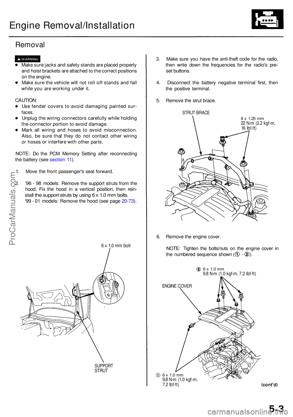
1 . Mov e th e fron t passenger' s sea t forward .
2 . '9 6 - 9 8 models : Remov e th e suppor t strut s fro m th e
hood . Fi x th e hoo d i n a vertica l position , the n rein -
stall th e suppor t strut s b y usin g 6 x 1. 0 m m bolts .
'99 - 0 1 models : Remov e th e hoo d (se e pag e 20-73 ).
6 x 1. 0 m m bol t
SUPPOR TSTRUT
3. Mak e sur e yo u hav e th e anti-thef t cod e fo r th e radio ,
the n writ e dow n th e frequencie s fo r th e radio' s pre -
set buttons .
4. Disconnec t th e batter y negativ e termina l first , the n
th e positiv e terminal .
5 . Remov e th e stru t brace .
STRUT BRAC E
8 x 1.2 5 mm22 N- m (2. 2 kgf-m ,16 Ibf-ft )
6. Remov e th e engin e cover .
NOTE : Tighte n th e bolts/nut s o n th e engin e cove r i n
th e numbere d sequenc e show n ( - ).
6 x 1. 0 m m9.8 N- m (1. 0 kgf-m , 7. 2 Ibf-ft )
ENGIN E COVE R
6 x 1. 0 m m9.8 N- m (1. 0 kgf-m ,7.2 Ibf-ft )
ProCarManuals.com
Page 378 of 1954

Engine Removal/Installatio n
Installation (cont'd )
5. Instal l th e transmissio n beam , the n tighte n th e bolt s
in th e numbere d sequenc e show n ( ) .
12 x 1.2 5 mm54 N- m (5. 5 kgf-m ,40 Ibf-ft )10 x 1.2 5 mm38 N- m (3. 9 kgf-m ,28 Ibf-ft )
10 x 1.2 5 mm38 N- m (3. 9 kgf-m ,28 Ibf-ft )
6. Tighte n th e lef t fron t moun t mountin g bolt .
12 x 1.2 5 mm74 N- m (7. 5 kgf-m ,52 Ibf-ft )
7. Tighte n th e righ t fron t moun t mountin g bolt .
12 x 1.2 5 mm74 N- m (7. 5 kgf-m ,52 Ibf-ft )
8. D o th e followin g check s an d adjustments :
Chec k tha t th e se t ring s o n th e end s o f th e drive -
shaf t an d intermediat e shaf t clic k int o place .
CAUTION : Us e ne w se t rings .
Adjus t th e shif t cabl e (se e sectio n 14 ).
Adjus t th e throttl e cabl e (se e sectio n 11 ).
Adjus t th e cruis e contro l cabl e (se e sectio n 4 ).
Refil l th e engin e wit h engin e oi l (se e pag e 8-4 ).
Refil l th e transmissio n wit h AT F (se e sectio n 14 ).
Refil l th e differentia l wit h differentia l oi l (se e
sectio n 15 ).
Refil l th e radiato r wit h engin e coolan t (se e pag e
10-5).
Blee d ai r fro m th e coolin g syste m a t th e blee d
bolt wit h th e heate r valv e ope n (se e pag e 10-5 ).
Clea n th e batter y post s an d cabl e terminal s wit h
sandpaper , assembl e them , the n appl y greas e to
preven t corrosion .
Inspec t fo r fue l leakag e (se e sectio n 11 ).
— Afte r assemblin g al l fue l lin e parts , tur n o n
th e ignitio n switc h (d o no t operat e th e starter )
s o tha t th e fue l pum p operate s fo r approxi -
matel y 2 second s an d pressurize s th e fue l
line .
— Repea t thi s operatio n 2 or 3 times , the n chec k
for fue l leakag e a t an y poin t i n th e fue l line .
Ente r th e anti-thef t cod e fo r th e radio , the n ente r
th e customer' s radi o statio n presets .
ProCarManuals.com
Page 401 of 1954
Cylinder Head s
Remova l
Make sur e jack s an d safet y stand s ar e
place d properl y an d hois t bracket s ar e attache d t o th e
correc t position s o n th e engine .
CAUTION :
Us e fende r cover s t o avoi d damagin g painte d sur -
faces .
Unplu g th e wirin g connector s carefull y whil e holdin g
th e connecto r portio n to avoi d damage .
T o avoi d damagin g th e cylinde r head , wai t unti l th e
engin e coolan t temperatur e drop s belo w 100° F (38°C )
befor e loosenin g th e retainin g bolts .
NOTE :
Unspecifie d item s ar e common .
Mar k al l wirin g an d hose s t o avoi d misconnection .
Also , b e sur e tha t the y d o no t contac t othe r wirin g o r
hose s o r interfer e wit h othe r parts .
Inspec t th e timin g bel t befor e removin g th e cylinde r
head.
Turn th e crankshaf t pulle y s o tha t th e No . 1 pisto n i s
a t to p dea d cente r (TDC) .
D o th e PC M Memor y Settin g afte r reconnectin g th e
batter y (se e sectio n 11 ).
1 . Remov e th e suppor t strut s fro m th e hood . Fi x th e
hoo d i n a vertica l position , the n reinstal l th e sup -
por t strut s b y usin g 6 x 1. 0 m m bolt s (se e pag e 5-3 ).
2 . Mak e sur e yo u hav e th e anti-thef t cod e fo r th e radio ,
the n writ e dow n th e frequencie s fo r th e radio' s pre -
set buttons .
3. Disconnec t th e batter y negativ e termina l first , the n
th e positiv e terminal .
4 . Drai n th e engin e coolan t (se e pag e 10-5 ).
5 . Remov e th e stru t brac e (se e pag e 5-3 ).
6 . Remov e th e engine cover (se e pag e 5-3 ).
7 . Remov e th e intak e ai r duc t an d ai r cleane r housin g
assembl y (se e pag e 5-4 ). 8
. Remov e th e throttl e cove r (se e pag e 5-4 ).
9 . Remov e th e throttl e cabl e an d cruis e contro l cabl e
b y loosenin g th e locknuts , the n sli p th e cabl e end s
ou t o f th e accelerato r linkag e (se e pag e 5-4 ).
NOTE :
Take car e no t t o ben d th e cabl e whe n removin g
it . Alway s replac e an y kinke d cabl e wit h a ne w
one .
Adjus t th e throttl e cabl e whe n installin g (se e
sectio n 11 ).
Adjus t th e cruis e contro l cabl e whe n installin g
(se e sectio n 23 ).
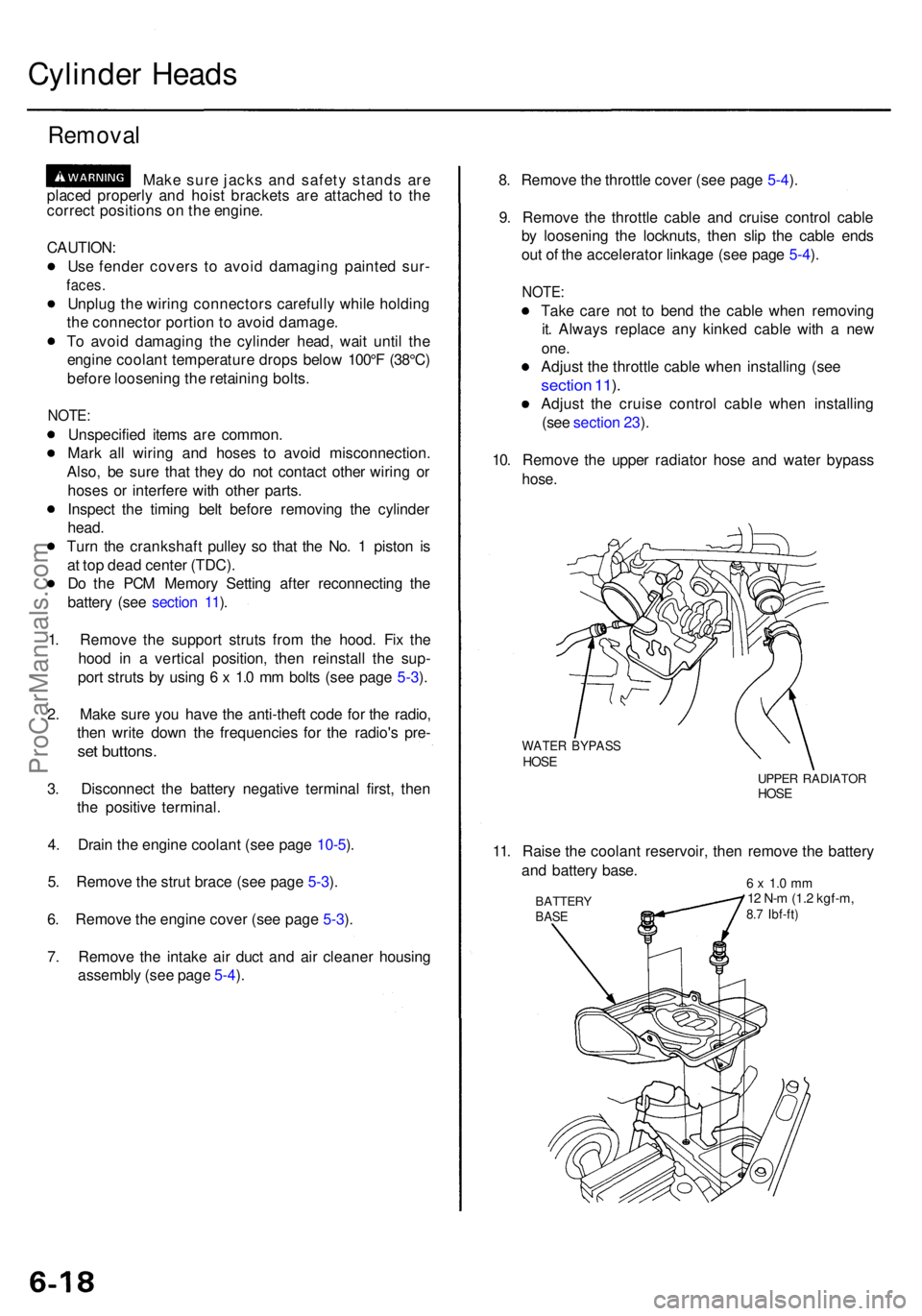
10 . Remov e th e uppe r radiato r hos e an d wate r bypas s
hose.
WATE R BYPAS SHOSEUPPE R RADIATO RHOSE
11. Rais e th e coolan t reservoir , the n remov e th e batter y
an d batter y base .
BATTER YBASE
6 x 1. 0 m m12 N- m (1. 2 kgf-m ,8.7 Ibf-ft )
ProCarManuals.com
Page 428 of 1954
Cylinder Head s
Installatio n (cont'd )
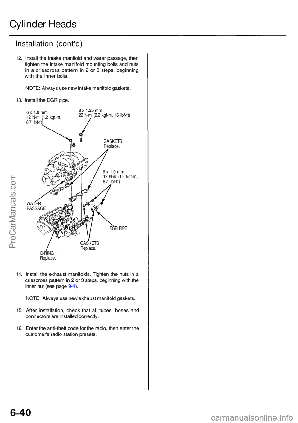
12. Instal l th e intak e manifol d an d wate r passage , the n
tighte n th e intak e manifol d mountin g bolt s an d nut s
i n a crisscros s patter n i n 2 o r 3 steps , beginnin g
wit h th e inne r bolts .
NOTE : Alway s us e ne w intak e manifol d gaskets .
13 . Instal l th e EG R pipe .
6 x 1. 0 m m12 N- m (1. 2 kgf-m ,
8. 7 Ibf-ft )
8 x 1.2 5 mm22 N- m (2. 2 kgf-m , 1 6 Ibf-ft )
GASKET S
Replace.
6 x 1. 0 m m12 N- m (1. 2 kgf-m ,
8. 7 Ibf-ft )
WATE R
PASSAG E
EGR PIP E
GASKET S
Replace.O-RING
Replace .
14. Instal l th e exhaus t manifolds . Tighte n th e nut s i n a
crisscros s patter n in 2 or 3 steps , beginnin g wit h th e
inne r nu t (se e pag e 9-4 ).
NOTE : Alway s us e ne w exhaus t manifol d gaskets .
15 . Afte r installation , chec k tha t al l tubes , hose s an d
connector s ar e installe d correctly .
16 . Ente r th e anti-thef t cod e fo r th e radio , the n ente r th e
customer' s radi o statio n presets .
ProCarManuals.com
Page 625 of 1954
PCM Memory Setting
NOTE: The PCM reset procedure and disconnecting the
battery or the BACK UP RADIO (7.5 A) fuse cancels the
PCM memory for idle control. The following procedure
is needed after the PCM reset procedure and reconnect-
ing the battery or the BACK UP RADIO (7.5 A) fuse.
1. Start the engine. Hold the engine at 3,000 rpm with
no load (in Park or neutral) until the radiator fan
comes on.
2. Let the engine idle for approx. 5 minutes under the
following conditions:
• Transmission in Park or neutral
• A/C switch OFF
• Headlights OFF
• Rear defogger OFFProCarManuals.com
Page 632 of 1954

Fuel Suppl y Syste m
System Descriptio n
The fue l suppl y syste m consist s o f a fue l tank , in-tan k
high-pressur e fue l pump , PGM-F I mai n relay , fue l filter ,
fue l pressur e regulator , fue l pressur e regulato r contro l
solenoi d valve , injectors , an d fue l deliver y an d retur n
lines . Thi s syste m deliver s pressure-regulate d fue l t o th e
injector s an d cut s th e fue l deliver y whe n th e engin e i s
no t running .
Fuel Pressur e
Relieving
Befor e disconnectin g fue l pipe s o r hoses , releas e pres -
sur e fro m th e syste m b y loosenin g th e servic e bol t o n
top o f th e fue l filter .
SERVIC E
BOL T
12 N- m(1.2 kgf-m , 8. 7 Ibf-ft )
FUE L
FILTE R
SHOP TOWE L
NOTE:
• A fue l pressur e gaug e can be attache d a t th e ser -
vic e bol t hole .
• Alway s replac e th e washe r betwee n th e servic e
bol t an d th e specia l banj o bol t wheneve r th e ser -
vic e bol t i s loosened .
• Replac e al l washer s wheneve r th e bolt s ar e
removed . Inspectio
n
1 . Reliev e fue l pressure .
2 . Remov e th e servic e bol t o n th e fue l filte r whil e hold -
in g th e banj o bol t wit h anothe r wrench . Attac h th e
specia l tool .
FUEL FILTE R
3. Star t th e engine . Measur e th e fue l pressur e wit h th e
engin e idlin g an d th e vacuu m hos e o f th e fue l pres -
sur e regulato r disconnecte d fro m th e fue l pressur e
regulato r an d pinched . I f th e engin e wil l no t start ,
turn th e ignitio n switc h O N (II) , wai t fo r tw o sec -
onds , tur n i t OFF , the n bac k o n agai n an d rea d th e
fue l pressure .
Pressur e shoul d be :
29 9 - 34 8 kP a (3.0 5 - 3.5 5 kgf/cm
2, 43. 4 - 50. 5 psi )
4 . Reconnec t vacuu m hos e to th e fue l pressur e regula -
tor.
Pressur e shoul d be :
24 0 - 28 9 kP a (2.4 5 - 2.9 5 kgf/cm2, 34. 8 - 41. 9 psi )
I f th e fue l pressur e i s no t a s specified , firs t chec k th e
fue l pum p (se e pag e 11-142 ). I f th e fue l pum p is OK ,
chec k th e following :
• I f th e fue l pressur e i s highe r tha n specified ,
inspec t for :
— Pinche d o r clogge d fue l retur n hos e o r line .
— Fault y fue l pressur e regulato r (se e pag e
11-135 ).
• I f th e fue l pressur e i s lowe r tha n specified , inspec t
for:
— Clogge d fue l filter .
— Fault y fue l pressur e regulato r (se e pag e
11-135 ).
— Fue l lin e leakage .
1
. Mak e sur e yo u hav e th e anti-thef t cod e fo r th e
radio , the n writ e dow n th e frequencie s fo r th e
radio' s prese t buttons .
2 . Disconnec t th e batter y negativ e cabl e fro m th e bat -
ter y negativ e terminal .
3. Remov e th e fue l fil l cap .
4. Us e a bo x en d wrenc h o n th e servic e bol t a t th e fue l
filte r whil e holdin g th e specia l banj o bol t wit h
anothe r wrench .
5. Plac e a ra g o r sho p towe l ove r th e servic e bolt .
6 . Slowl y loose n th e servic e bol t on e complet e turn .
7 . Reconnec t th e battery , ente r th e anti-thef t cod e fo r
th e radio , the n ente r th e customer' s radi o statio n
presets .
•
D o no t smok e whil e workin g o n th e fue l system .
Kee p ope n flame s o r spark s awa y fro m you r wor k area .
• B e sur e t o reliev e fue l pressur e whil e th e ignitio n
switch is off .
CLAM P
FUE
L
PRESSUR E
REGULATO R FUE
L
PRESSUR E
GAUG E
07406-004000 1
ProCarManuals.com
Page 759 of 1954

Troubleshooting Procedure s
Checking th e Diagnosti c Troubl e Cod e (DTC )
wit h a n OB D II Sca n Too l o r Hond a PG M Teste r
When th e PC M sense s a n abnormalit y i n th e inpu t o r outpu t systems , th e indicato r ligh t i n th e gaug e assembl y wil l
blink . Whe n th e 16 P Dat a Lin k Connecto r (DLC ) (locate d behin d th e ashtray ) i s connecte d to th e OB D II Sca n Too l o r Hond a
PG M Teste r a s shown , th e sca n too l o r teste r wil l indicat e th e Diagnosti c Troubl e Cod e (DTC ) whe n th e ignitio n switc h i s
turne d O N (II) .
If th e indicato r ligh t o r th e MI L ha s bee n reporte d on , o r i f a driveabilit y proble m is suspected , follo w thi s procedure :
1 . Connec t th e OB D II Sca n Too l (conformin g to SA E J1978 ) o r Hond a PG M Teste r t o th e 16 P DLC .
(Se e th e OB D II Sca n Too l o r Hond a PG M Teste r user' s manua l fo r specifi c instructions . I f yo u ar e usin g th e Hond a
PG M Tester , mak e sur e it i s se t t o th e SA E DT C type. )
2 . Tur n th e ignitio n switc h O N (II) , an d observ e th e DT C o n th e screen .
3 . Recor d al l fue l an d emission s DTCs , A/ T DTCs , an d freez e data .
4 . I f ther e is a fue l an d emission s DTC , firs t chec k th e fue l an d emission s syste m a s indicate d b y th e DT C (excep t fo r DT C
P0700) . DT C P070 0 mean s ther e is on e o r mor e A/ T DTC , an d n o problem s wer e detecte d in th e fue l an d emission s circui t
of th e PCM .
5. Ge t th e anti-thef t cod e fo r th e radio , the n writ e dow n th e radi o statio n presets .
6 . Rese t th e memor y wit h th e PG M Teste r o r b y removin g th e BAC K U P fus e i n th e under-hoo d fuse/rela y bo x fo r mor e
tha n 1 0 seconds .
7 . Driv e th e vehicl e fo r severa l minute s a t speed s ove r 3 0 mp h (5 0 km/h) , an d the n rechec k fo r DTCs . I f th e A/ T DT C
returns , g o t o th e Symptom-to-Componen t Char t (pag e 14-5 6 an d 14-57 ). I f th e DT C doe s no t return , ther e wa s a n inter -
mitten t proble m withi n th e circuit . Mak e sur e al l pin s an d terminal s i n th e circui t ar e tight , an d the n g o t o ste p 8 .
8 . Ente r th e anti-thef t cod e fo r th e radio , rese t th e radi o prese t stations , an d se t th e clock .
ProCarManuals.com