1996 ACURA RL KA9 change time
[x] Cancel search: change timePage 544 of 1954

PCM Data
You can retrieve data from the PCM by connecting the OBD II scan tool or the Honda PGM Tester to the Data Link
Connector (DLC). The items listed in the table below conform to SAE recommended practice. The Honda PGM Tester also
reads data beyond that recommended by SAE so that this data may help you find the causes of intermittent problems.
NOTE:
• The "operating values" listed are approximate and may vary depending on the environment and the individual vehicle.
• Unless noted otherwise, "at idle speed" means idling with the engine completely warmed up, transmission in Park or
neutral, and the A/C and all accessories turned off.
Data
Description
Operating Value
Freeze Data
Diagnostic
Trouble Code
(DTC)
If the PCM detects a problem, it will store it as a code
consisting of one letter and four numbers.
Depending on the problem, an SAE-defined code
(P0xxx)
or a
Honda-defined code
(P1xxx)
will
be
output
to the tester.
If no problem is detected,
there is no output.
YES
Engine Speed
The PCM computes engine speed from the signals sent
from the Crankshaft Position (CKP) sensor.
This data is used for determining the time and amount
of fuel injection.
Nearly the same as
tachometer indication at
idle speed:
650 ± 50 rpm
YES
Vehicle Speed
The PCM converts pulse signals from the Vehicle
Speed Sensor (VSS) into speed data.
Nearly the same as
speedometer indication
YES
Manifold
Absolute
Pressure (MAP)
The absolute pressure created in the intake manifold by
engine load and speed.
With engine stopped:
Nearly the same as atmo-
spheric pressure.
At idle speed:
24 - 37
kPa
(180
-
280
mmHg, 7.1 - 11.0 inHg)
YES
Engine Coolant
Temperature
(ECT)
The ECT sensor converts coolant temperature into
voltage and signals the PCM. The sensor is a thermistor
whose internal resistance changes with coolant
temperature. The PCM uses the voltage signals from
the ECT sensor to determine the amount of injected
fuel.
With cold engine:
Same as ambient temper-
ature and IAT
With engine warmed up:
approx. 158 - 212°F
(70 - 100°C)
YES
Heated Oxygen
Sensor (HO2S)
(Bank 1, Sensor 1)
(Bank 2, Sensor 1)
(Sensor 2)
The HO2S detects the oxygen content in the exhaust
gas and sends voltage signals to the PCM. Based on
these signals, the PCM controls the air/fuel ratio. When
the oxygen content is high (that is, when the ratio is
leaner than the stoichiometric ratio), the voltage signal
is lower. When the oxygen content is low (that is, when
the ratio is richer than the stoichiometric ratio), the
voltage signal is higher.
0.0 -
1.25
V
At idle speed:
about 0.1 - 0.9 V
NOProCarManuals.com
Page 579 of 1954

PGM-FI Syste m
Throttl e Positio n (TP ) Senso r
The sca n too l indicate s Diagnosti c Troubl e Cod e (DTC ) P0122 : A lo w voltag e proble m in th e Throttl e Positio n
(TP) senso r circuit .
The T P Senso r i s a potentiometer . I t i s connecte d t o th e throttl e valv e shaft . A s th e throttl e positio n changes , th e throttl e
position senso r varie s th e voltag e signa l t o th e PCM .
— Th e MI L ha s bee n reporte d on .
— DT C P012 2 is stored .
Proble m verification :
1 . Star t th e engine . Hol d th e
engin e a t 3,00 0 rp m wit h n o
loa d (i n Par k o r neutral ) unti l
th e radiato r fa n come s on ,
the n tur n th e ignitio n switc h
OFF.2. Turn the ignition switch ON (II).3. Chec k th e throttl e positio n
wit h th e sca n tool .
I s ther e approx . 10 % whe n
the throttl e is full y close dand approx . 90 % whe n th e
throttl e is full y opened ?
NO
Chec k fo r a n ope n i n the wire
(VCC 2 line) :
1. Tur n th e ignitio n switc h OFF .2. Disconnec t th e T P senso r con -
nector .
3 . Tur n th e ignitio n switc h O N (II) .
4 . Measur e voltag e betwee n
No. 1 termina l an d No . 3 termi -nal o n th e T P senso r connector . BRUS
H
HOLDE R
BRUS H
RESISTO R
YES
Is ther e abou t 5 V ?NO
YE S
Chec k fo r a n ope n o r shor t i n T Psensor :1. Tur n th e ignitio n switc h OFF .
2 . Measur e resistanc e betwee n
No . 1 termina l an d No . 2 ter -
mina l o n th e senso r sid e o f
T P senso r connecto r wit h th e
throttl e full y closed .
(T o pag e 11-81 )
*: wit h TC S*1: wit h VS A TERMINA
L
INNERBUSHIN GIDLEFUL LTHROTTL E
THROTTLEOPENING
Intermitten t failure , syste m is O K
a t thi s time . Chec k fo r poo r con -
nection s o r loos e wire s a t C11 3
(T P sensor ) C251 , C253 , C25 4
(locate d a t lef t shoc k tower) ,
C62 3 (TC S contro l unit) * C45 0
(VS A converte r unit)*
1 an d PCM . T
P SENSO R CONNECTO R (C113 )
Wir e sid e o f femal e terminal s
Chec k fo r a n ope n in wir e (VCC2 ,
line):Measur e voltag e betwee n D2 1
termina l an d D2 2 termina l o n th e
PC M connector . Wir
e sid e o f femal e terminal s
I s ther e abou t 5 V ? Repai
r ope n in th e wir e betwee n
PCM (D21 ) an d T P sensor .
NO
Substitut e a known-goo d PC M
an d rechec k (se e pag e 11-42 fo r
immobilize r information) . I f pre -
scribe d voltag e is no w available ,
replac e th e origina l PCM .Termina l sid e o fmal e terminal s
YES
PCM CONNECTO R D (22P )
OUTPU
T VOLTAG E (V )
ProCarManuals.com
Page 596 of 1954

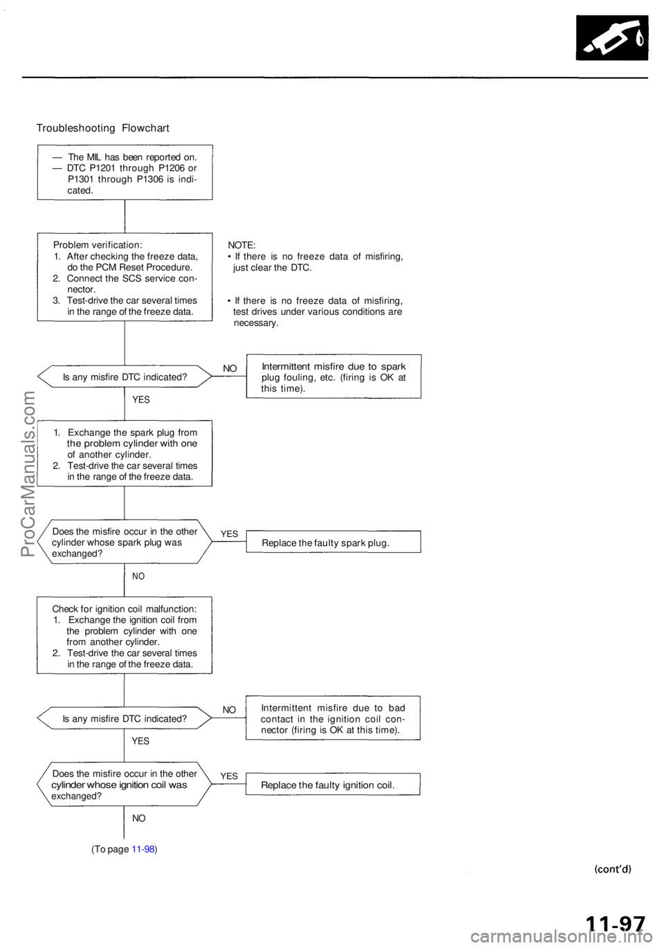
Troubleshooting Flowchar t
— Th e MI L ha s bee n reporte d on .
— DT C P120 1 throug h P120 6 o r
P130 1 throug h P130 6 i s indi -
cated .
Proble m verification :
1 . Afte r checkin g th e freez e data ,
d o th e PC M Rese t Procedure .
2 . Connec t th e SC S servic e con -
nector .
3 . Test-driv e th e ca r severa l time s
i n th e rang e o f th e freez e data .
I s an y misfir e DT C indicated ?
Doe s th e misfir e occu r i n th e othe r
cylinde r whos e spar k plu g wa s
exchanged ?
NO
Chec k fo r ignitio n coi l malfunction :
1 . Exchang e th e ignitio n coi l fro m
th e proble m cylinde r wit h on e
fro m anothe r cylinder .
2 . Test-driv e th e ca r severa l time s
i n th e rang e o f th e freez e data .
I s an y misfir e DT C indicated ?
YES
Doe s th e misfir e occu r i n th e othe rcylinde r whos e ignitio n coi l wa sexchanged ?
NO
(T o pag e 11-98 )
NOTE :• I f ther e i s n o freez e dat a o f misfiring ,
jus t clea r th e DTC .
• I f ther e i s n o freez e dat a o f misfiring ,
tes t drive s unde r variou s condition s ar e
necessary .
Intermittent misfir e du e t o spar kplug fouling , etc . (firin g i s O K a t
thi s time) .
Replac e th e fault y spar k plug .
Intermitten t misfir e du e t o ba d
contac t i n th e ignitio n coi l con -
necto r (firin g is O K a t thi s time) .
Replac e th e fault y ignitio n coil .
YES
NO
YE S
1. Exchang e th e spar k plu g fro mthe proble m cylinde r wit h on eof anothe r cylinder .
2 . Test-driv e th e ca r severa l time s
i n th e rang e o f th e freez e data .
YES
NO
ProCarManuals.com
Page 597 of 1954

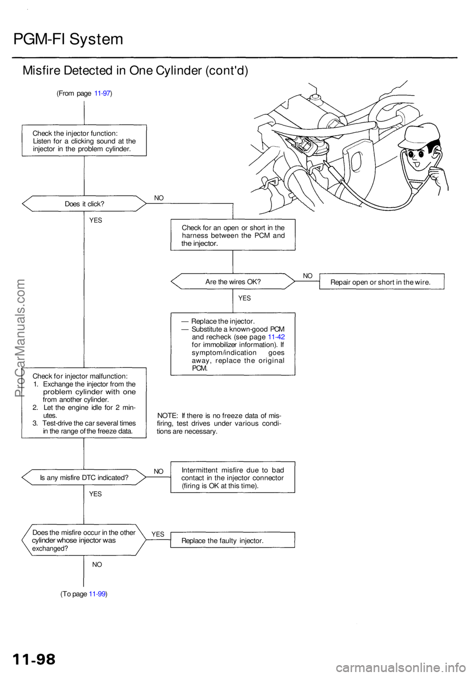
PGM-FI Syste m
Misfire Detecte d in On e Cylinde r (cont'd )
(From pag e 11-97 )
Chec k th e injecto r function :
Liste n fo r a clickin g soun d a t th e
injecto r i n th e proble m cylinder .
Doe s i t click ?
NO
YE SChec k fo r a n ope n o r shor t i n th e
harnes s betwee n th e PC M an d
the injector .
Are th e wire s OK ?
Chec k fo r injecto r malfunction :
1 . Exchang e th e injecto r fro m th e
proble m cylinde r wit h on efrom anothe r cylinder .
2 . Le t th e engin e idl e fo r 2 min -
utes .
3 . Test-driv e th e ca r severa l time s
i n th e rang e o f th e freez e data . Repai
r ope n o r shor t i n th e wire .
YES
— Replac e th e injector .
— Substitut e a known-goo d PC M
an d rechec k (se e pag e 11-42
fo r immobilize r information) . I f
symptom/indicatio n goe s
away , replac e th e origina l
PCM.
NOTE : I f ther e is n o freez e dat a o f mis -
firing , tes t drive s unde r variou s condi -
tion s ar e necessary .
I s an y misfir e DT C indicated ?
YES
Intermitten t misfir e du e t o ba d
contac t i n th e injecto r connecto r
(firin g is O K a t thi s time) .
Doe s th e misfir e occu r i n th e othe r
cylinde r whos e injecto r wa sexchanged ?Replace th e fault y injector .
NO
(T o pag e 11-99 )
YES
NO
N O
ProCarManuals.com
Page 611 of 1954

Idle Contro l Syste m
System Descriptio n
The idl e spee d o f th e engin e is controlle d b y th e Idl e Ai r Contro l (IAC ) Valve .
Th e valv e change s th e amoun t o f ai r bypassin g int o th e intak e manifol d i n respons e t o electri c curren t controlle d b y th e
PCM . Whe n th e IA C Valv e is activated , th e valv e open s to maintai n th e prope r idl e speed .
VARIOU S
SENSOR S
INTAK E
MANIFOL D
IDLEADJUSTIN GSCREW
1. Afte r th e engin e starts , th e IA C valv e open s fo r a certai n time . Th e amoun t o f ai r i s increase d t o rais e th e idl e spee d
abou t 15 0 - 30 0 rpm .
2 . Whe n th e coolan t temperatur e i s low , th e IA C valv e i s opene d t o obtai n th e prope r fas t idl e speed . Th e amoun t o f
bypasse d ai r i s thu s controlle d in relatio n to th e engin e coolan t temperature .
3 . Whe n th e idl e spee d is ou t o f specificatio n an d th e sca n too l doe s no t indicat e Diagnosti c Troubl e Cod e (DTC ) P050 5 o r
P1508 , chec k th e followin g items :
• Adjus t th e idl e spee d (se e pag e 11-124 )
• Ai r conditionin g signa l (se e pag e 11-116 )
• AL T F R signa l (se e pag e 11-118 )
• Starte r switc h signa l (se e pag e 11-119 )
• Transmissio n rang e signa l (se e sectio n 14 )
• PS P switc h signa l (se e pag e 11-120 )
• Brak e peda l positio n switc h signa l (se e pag e 11-122 )
• Idl e ai r contro l therma l valv e (se e pag e 11-123 )
• Hose s an d connection s
• IA C valv e an d it s mountin g O-ring s
4 . I f th e abov e item s ar e normal , substitut e a known-goo d IA C valv e an d readjus t th e idl e spee d (se e pag e 11-124 ).
I f th e idl e spee d stil l canno t b e adjuste d t o specificatio n (an d th e sca n too l doe s no t indicat e DT C P050 5 o r P1508 ) afte r
IA C valv e replacement , substitut e a known-goo d PC M an d rechec k (se e pag e 11-42 fo r immobilize r information) . I f
sympto m goe s away , replac e th e origina l PCM .
IDLEAIRCONTRO LTHERMA LVALVE
IAC VALV E
FromPGM-F IMAINRELA Y
ENGIN E COOLAN T
ProCarManuals.com
Page 614 of 1954

— Th e MI L ha s bee n reporte d on .
— DT C P150 8 is stored .
Proble m verification :
1. D o th e PC M Rese t Procedure .2. Star t th e engine .
Is DT C P150 8 indicated ?
YES
Chec k fo r a n ope n i n the wire
(IGP 1 line) :
1 . Tur n th e ignitio n switc h OFF .
2 . Disconnec t th e IA C valv e con -
nector .
3 . Tur n th e ignitio n switc h O N (II) .
4 . Measur e voltag e betwee n bod y
groun d an d th e IA C valv e con -
necto r termina l No . 2 .
I s ther e batter y voltage ?
I s ther e batter y voltage ?
YES
Chec k th e IA C valv e function :
Momentaril y connec t PC M con -
necto r terminal s A 5 an d A1 2 wit h
a jumpe r wire severa l times .
Doe s th e IA C valv e click ?
YES
Substitut e a known-goo d PC M
an d rechec k (se e pag e 11-42 fo r
immobilize r information) . I f symp -
tom/indicatio n goe s away , replac e
th e origina l PCM .
SHAF T
Intermitten t failure , syste m is O K
a t thi s time . Chec k fo r poo r con -
nection s o r loos e wire s a t C25 3
(locate d a t lef t shoc k tower) ,
C12 9 (IA C valve ) an d PCM .
SPRIN G
IAC VALV E CONNECTO R (C129 )
Repair ope n in th e wir e betwee n
IA C valv e an d PGM-F I mai n relay . Wir
e sid e o f femal e terminal s
PCM CONNECTO R A (26P )
Repai r ope n o r shor t i n th e wir e
betwee n PC M (A5 ) an d IA C valve . Wir
e sid e o f femal e terminal sJUMPER WIR E
Replac e th e IA C valve .NO
NO
Chec k fo r a n ope n o r shor t i n th ewir e (IAC V line) :
1 . Tur n th e ignitio n switc h OF F
an d reconnec t th e IA C valv e
connector .2. Disconnec t th e PC M connec -tor A (26P) .3. Tur n th e ignitio n switc h O N (II) .
4 . Measur e voltag e betwee n
bod y groun d an d PC M con -
necto r termina l A5 .
NO
YE S
VALV E
To INTAK EMANIFOL DFrom AI RCLEANE RCOIL
NO
Idl e Ai r Contro l (IAC ) Valv e
The sca n too l indicate s Diagnosti c Troubl e Cod e (DTC ) P1508 : A proble m in th e Idl e Ai r Contro l (IAC ) valv e
circuit .
The IA C Valv e change s th e amoun t o f ai r bypassin g th e throttl e bod y i n respons e t o a curren t signa l fro m th e PC M in
orde r t o maintai n th e prope r idl e speed .
ProCarManuals.com
Page 671 of 1954

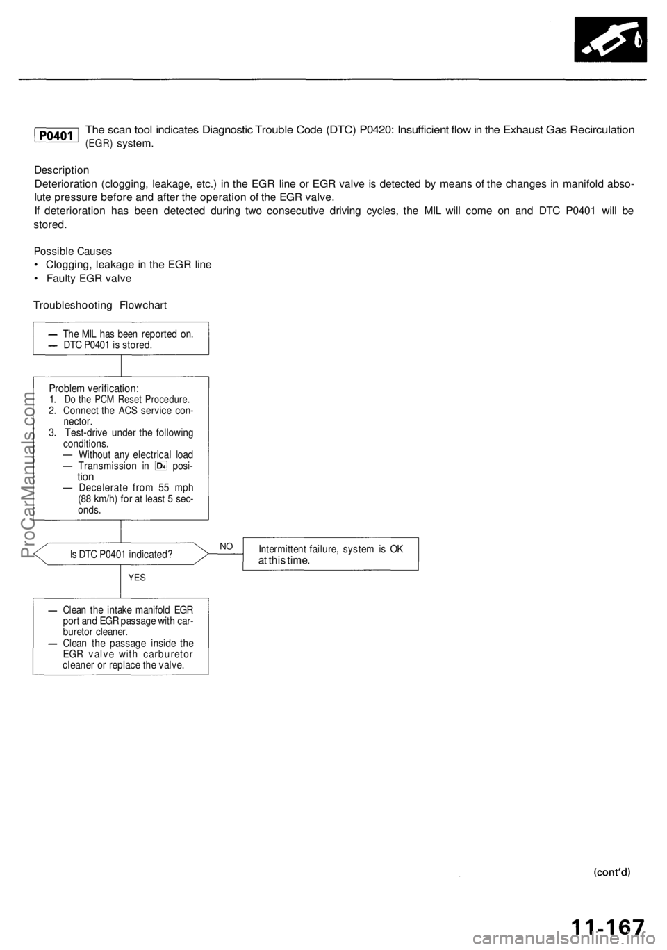
The scan tool indicates Diagnostic Trouble Code (DTC) P0420: Insufficient flow in the Exhaust Gas Recirculation
(EGR)
system.
Description
Deterioration (clogging, leakage, etc.) in the EGR line or EGR valve is detected by means of the changes in manifold abso-
lute pressure before and after the operation of the EGR valve.
If deterioration has been detected during two consecutive driving cycles, the MIL will come on and DTC P0401 will be
stored.
Possible Causes
• Clogging, leakage in the EGR line
• Faulty EGR valve
Troubleshooting Flowchart
Is DTC P0401 indicated?
Intermittent failure, system is OK
at this time.
YES
Clean the intake manifold EGR
port and EGR passage with car-
buretor cleaner.
Clean the passage inside the
EGR valve with carburetor
cleaner or replace the valve.
NO
Problem verification:
1. Do the PCM Reset Procedure.
2. Connect the ACS service con-
nector.
3. Test-drive under the following
conditions.
— Without any electrical load
— Transmission in posi-
tion
— Decelerate from 55 mph
(88 km/h) for at least 5 sec-
onds.
The MIL has been reported on.
DTC P0401 is stored.ProCarManuals.com
Page 1064 of 1954

Master Cylinder/Brak e Booste r
Brake Booste r Inspectio n
Functiona l Tes t
1 . Wit h th e engin e stopped , pres s th e brak e peda l sev -
eral time s t o deplet e th e vacuu m reservoir , the n
pres s th e peda l har d an d hol d i t fo r 1 5 seconds . I f
th e peda l sinks , eithe r th e maste r cylinde r i s
bypassin g internally , o r th e brak e syste m (maste r
cylinder , lines , modulator , o r caliper ) i s leaking .
2 . Star t th e engin e wit h th e peda l pressed . I f th e peda l
sinks slightly , th e vacuu m booste r i s operatin g nor -
mally . I f th e peda l heigh t doe s no t vary , th e booste r
o r chec k valv e is faulty .
3. Wit h th e engin e running , pres s th e brak e peda l light -
ly. Appl y jus t enoug h pressur e t o hol d bac k auto -
mati c transmissio n creep . I f th e brak e peda l sink s
mor e tha n 2 5 m m (1. 0 in. ) i n 3 minutes , th e maste r
cylinde r i s faulty . A sligh t chang e i n peda l heigh t
whe n th e A/ C compresso r cycle s o n an d of f i s nor -
mal . (Th e A/ C compresso r loa d change s th e vacuu m
availabl e to th e booster. )
Leak Tes t
1 . Pres s th e brak e peda l wit h th e engin e running , the n
sto p th e engine . I f th e peda l heigh t doe s no t var y
whil e presse d fo r 3 0 seconds , th e vacuu m booste r i s
OK . I f th e peda l rises , th e booste r i s faulty .
2 . Wit h th e engin e stopped , pres s th e brak e peda l sev -
era l time s usin g norma l pressure . Whe n th e peda l i s
firs t pressed , i t shoul d b e low . O n consecutiv e appli -
cations , th e peda l heigh t shoul d graduall y rise . I f th e
peda l positio n doe s no t vary , chec k th e booste r
chec k valve .
Booste r Chec k Valv e Tes t
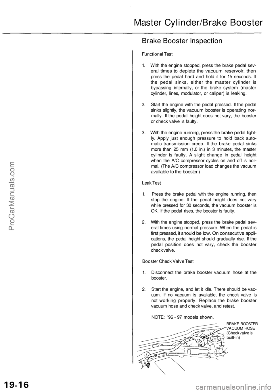
1 . Disconnec t th e brak e booste r vacuu m hos e a t th e
booster .
2 . Star t th e engine , an d le t i t idle . Ther e shoul d b e vac -
uum . I f n o vacuu m is available , th e chec k valv e i s
no t workin g properly . Replac e th e brak e booste r
vacuu m hos e an d chec k valve , an d retest .
NOTE : '9 6 - 9 7 model s shown .
BRAKE BOOSTE RVACUUM HOS E
(Chec k valv e is
built-in )
ProCarManuals.com