DTC 51 Switch Condition Signal Circuit
CIRCUIT DESCRIPTION
Park/Neutral Position Switch
The ECM uses the signals from the park/neutral position switch to determine whether the transmission is in park
or neutral, or in some other position.
Air Conditioning Switch Signal
The ECM uses the output from the air conditioning switch to determine whether or not the air conditioning is
operating so that it can increase the idling speed of the engine if necessary.
Throttle Position Sensor IDL Signal
The IDL contacts are mounted in the throttle position sensor, and detects the idle condition.
����� �����DTC No.������������������� �������������������Diagnostic Trouble Code Detecting Condition�������������� ��������������Trouble Area
����� �
���� �
���� �
���� �
���� �
���� �����
51
������������������� �
������������������ �
������������������ �
������������������ �
������������������ �
������������������ �������������������
(1) 3 sec. or more after engine starts with
closed throttle position switch OFF
(IDL1)
(2) Park/neutral position switch: OFF
(Shift position in ºRº, ºDº, º2º or º1º
position.)
(3) A/C switch ON�������������� �
������������� �
������������� �
������������� �
������������� �
������������� ��������������
�Throttle position sensor IDL circuit
�Accelerator pedal and cable
�Park/neutral position switch
�A/C switch circuit
�ECM
HINT: In this circuit, diagnosis can only be made in the test mode.
± ENGINE2JZ±GTE ENGINE TROUBLESHOOTINGEG±571
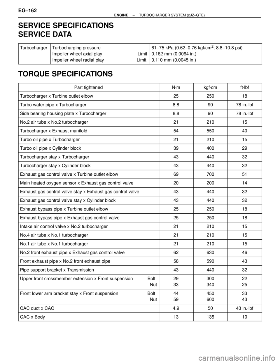
SERVICE SPECIFICATIONS
SERVICE DATA
������ �
����� �
����� ������
Turbocharger��������������� �
�������������� �
�������������� ���������������
Turbocharging pressure
Impeller wheel axial play Limit
Impeller wheel radial play Limit����������������� �
���������������� �
���������������� �����������������
61±75 kPa (0.62±0.76 kgf/cm2, 8.8±10.8 psi)
0.162 mm (0.0064 in.)
0.110 mm (0.0045 in.)
TORQUE SPECIFICATIONS
��������������������� �
�������������������� ���������������������Part tightened������ �
����� ������NVm������ �
����� ������kgfVcm������ �
����� ������ftVlbf
��������������������� ���������������������Turbocharger x Turbine outlet elbow������ ������25������ ������250������ ������18
��������������������� ���������������������Turbo water pipe x Turbocharger������ ������8.8������ ������90������ ������78 in.Vlbf
��������������������� ���������������������Side bearing housing plate x Turbocharger������ ������8.8������ ������90������ ������78 in.Vlbf
��������������������� ���������������������No.2 air tube x No.2 turbocharger������ ������21������ ������210������ ������15��������������������� �
�������������������� ���������������������Turbocharger x Exhaust manifold
������ �
����� ������54
������ �
����� ������550
������ �
����� ������40
��������������������� ���������������������Turbo oil pipe x Turbocharger������ ������21������ ������210������ ������15
��������������������� ���������������������Turbo oil pipe x Cylinder block������ ������39������ ������400������ ������29
��������������������� ���������������������Turbocharger stay x Turbocharger������ ������43������ ������440������ ������32��������������������� �
�������������������� ���������������������Turbocharger stay x Cylinder block
������ �
����� ������43
������ �
����� ������440
������ �
����� ������32
��������������������� ���������������������Exhaust gas control valve x Turbine outlet elbow������ ������69������ ������700������ ������51
��������������������� ���������������������Main heated oxygen sensor x Exhaust gas control valve������ ������20������ ������200������ ������14
��������������������� ���������������������Exhaust gas control valve stay x Exhaust gas control valve������ ������43������ ������440������ ������32��������������������� �
�������������������� ���������������������Exhaust gas control valve stay x Cylinder block
������ �
����� ������43
������ �
����� ������440
������ �
����� ������32
��������������������� ���������������������Exhaust bypass pipe x Turbine outlet elbow������ ������25������ ������250������ ������18
��������������������� ���������������������Exhaust bypass pipe x Exhaust gas control valve������ ������25������ ������250������ ������18
��������������������� ���������������������Intake air control valve x No.2 turbocharger������ ������21������ ������210������ ������15��������������������� �
��������������������No.4 air tube x No.1 turbocharger������ �
�����21������ �
�����210������ �
�����15��������������������� �
�������������������� ���������������������No.1 air tube x No.1 turbocharger
������ �
����� ������21
������ �
����� ������210
������ �
����� ������15
��������������������� ���������������������No.2 front exhaust pipe x Exhaust gas control valve������ ������62������ ������630������ ������46
��������������������� ���������������������Front exhaust pipe x No.2 front exhaust pipe������ ������58������ ������590������ ������43
��������������������� ���������������������Pipe support bracket x Transmission������ ������43������ ������440������ ������32��������������������� �
�������������������� �
�������������������� ���������������������
Upper front crossmember extension x Front suspension Bolt
Nut
������ �
����� �
����� ������
29
33
������ �
����� �
����� ������
300
340
������ �
����� �
����� ������
22
25
��������������������� �
�������������������� ���������������������
Front lower arm bracket stay x Front suspension Bolt
Nut������ �
����� ������
44
59������ �
����� ������
450
600������ �
����� ������
33
43
��������������������� ���������������������CAC duct x CAC������ ������4.9������ ������50������ ������43 in.Vlbf
��������������������� ���������������������CAC x Body������ ������13������ ������135������ ������10
EG±162± ENGINETURBOCHARGER SYSTEM (2JZ±GTE)