Page 1468 of 2543
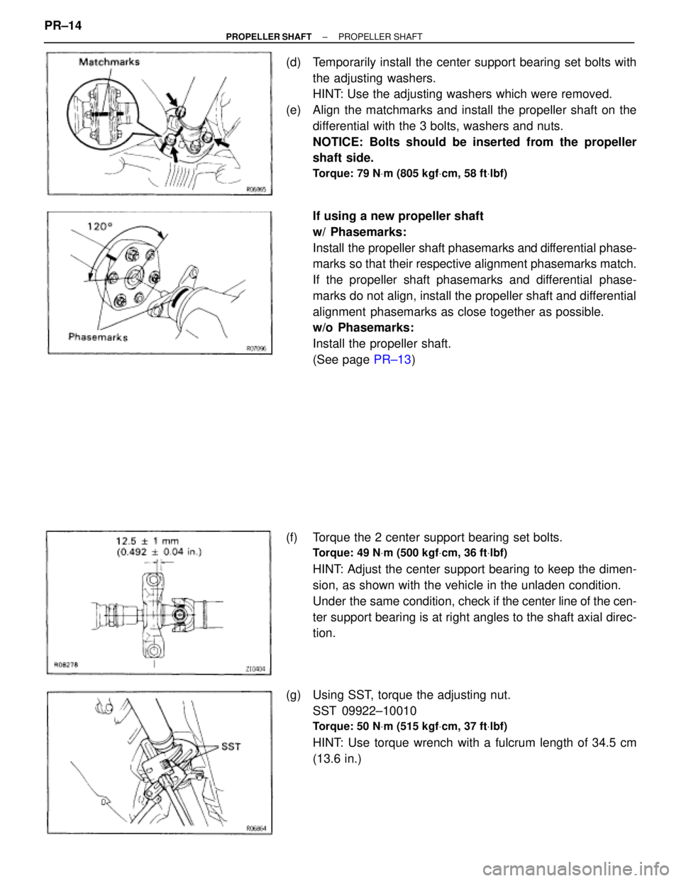
(d) Temporarily install the center support bearing set bolts with
the adjusting washers.
HINT: Use the adjusting washers which were removed.
(e) Align the matchmarks and install the propeller shaft on the
differential with the 3 bolts, washers and nuts.
NOTICE: Bolts should be inserted from the propeller
shaft side.
Torque: 79 NVm (805 kgfVcm, 58 ftVlbf)
If using a new propeller shaft
w/ Phasemarks:
Install the propeller shaft phasemarks and differential phase-
marks so that their respective alignment phasemarks match.
If the propeller shaft phasemarks and differential phase-
marks do not align, install the propeller shaft and differential
alignment phasemarks as close together as possible.
w/o Phasemarks:
Install the propeller shaft.
(See page PR±13)
(f) Torque the 2 center support bearing set bolts.
Torque: 49 NVm (500 kgfVcm, 36 ftVlbf)
HINT: Adjust the center support bearing to keep the dimen-
sion, as shown with the vehicle in the unladen condition.
Under the same condition, check if the center line of the cen-
ter support bearing is at right angles to the shaft axial direc-
tion.
(g) Using SST, torque the adjusting nut.
SST 09922±10010
Torque: 50 NVm (515 kgfVcm, 37 ftVlbf)
HINT: Use torque wrench with a fulcrum length of 34.5 cm
(13.6 in.) PR±14
± PROPELLER SHAFTPROPELLER SHAFT
Page 1481 of 2543
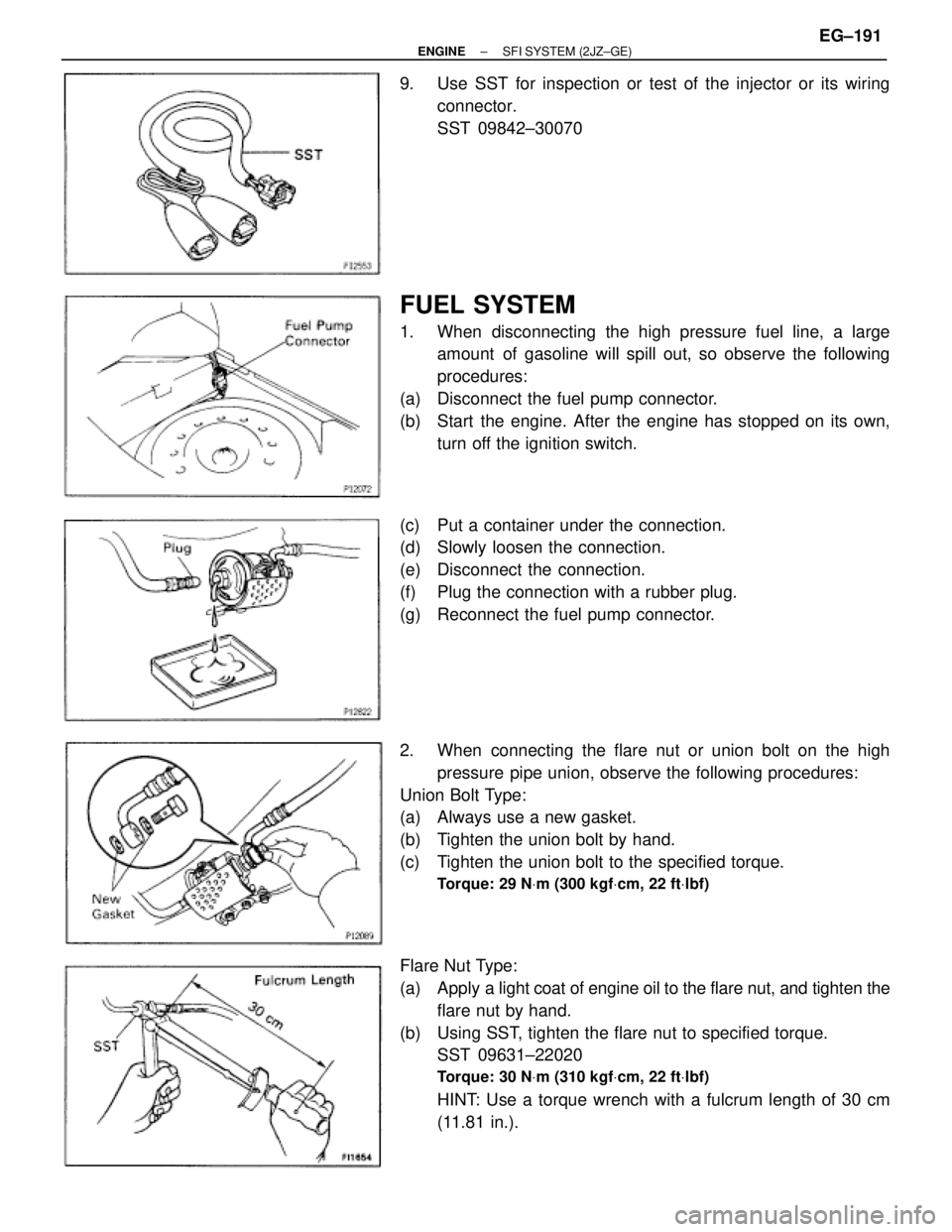
9. Use SST for inspection or test of the injector or its wiring
connector.
SST 09842±30070
FUEL SYSTEM
1. When disconnecting the high pressure fuel line, a large
amount of gasoline will spill out, so observe the following
procedures:
(a) Disconnect the fuel pump connector.
(b) Start the engine. After the engine has stopped on its own,
turn off the ignition switch.
(c) Put a container under the connection.
(d) Slowly loosen the connection.
(e) Disconnect the connection.
(f) Plug the connection with a rubber plug.
(g) Reconnect the fuel pump connector.
2. When connecting the flare nut or union bolt on the high
pressure pipe union, observe the following procedures:
Union Bolt Type:
(a) Always use a new gasket.
(b) Tighten the union bolt by hand.
(c) Tighten the union bolt to the specified torque.
Torque: 29 NVm (300 kgfVcm, 22 ftVlbf)
Flare Nut Type:
(a) Apply a light coat of engine oil to the flare nut, and tighten the
flare nut by hand.
(b) Using SST, tighten the flare nut to specified torque.
SST 09631±22020
Torque: 30 NVm (310 kgfVcm, 22 ftVlbf)
HINT: Use a torque wrench with a fulcrum length of 30 cm
(11.81 in.).
± ENGINESFI SYSTEM (2JZ±GE)EG±191
Page 1504 of 2543
FUEL PRESSURE PULSATION DAMPER
INSTALLATION
1. INSTALL FUEL PRESSURE PULSATION DAMPER
(a) Install the fuel inlet pipe and pulsation damper with 2 new
gaskets.
HINT: Different sized gaskets are used for the upper (large
size) and lower (small size).
(b) Using SST, tighten the pulsation damper.
SST 09612±24014 (09617±24011)
Torque:
41 NVm (420 kgfVcm, 30 ftVlbf)
35 NVm (350 kgfVcm, 25 ftVlbf) for SST
HINT: Use a torque wrench with a fulcrum length of 30 cm
(11.81 in.).
2. INSTALL STARTER
(See starter installation in Starting System)
4. CHECK FOR FUEL LEAKS
(See item 5 in fuel system in precaution) EG±214
± ENGINESFI SYSTEM (2JZ±GE)
Page 1552 of 2543
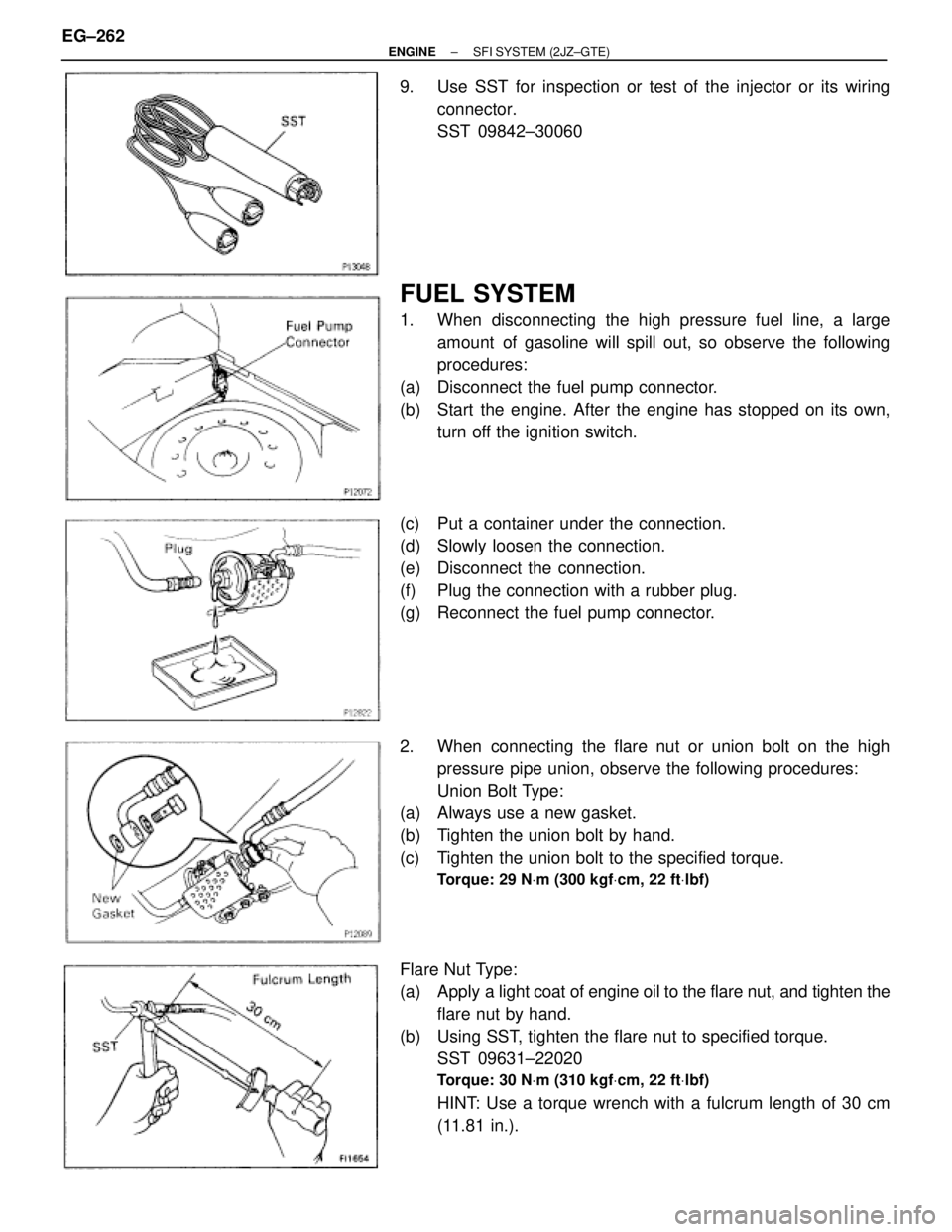
9. Use SST for inspection or test of the injector or its wiring
connector.
SST 09842±30060
FUEL SYSTEM
1. When disconnecting the high pressure fuel line, a large
amount of gasoline will spill out, so observe the following
procedures:
(a) Disconnect the fuel pump connector.
(b) Start the engine. After the engine has stopped on its own,
turn off the ignition switch.
(c) Put a container under the connection.
(d) Slowly loosen the connection.
(e) Disconnect the connection.
(f) Plug the connection with a rubber plug.
(g) Reconnect the fuel pump connector.
2. When connecting the flare nut or union bolt on the high
pressure pipe union, observe the following procedures:
Union Bolt Type:
(a) Always use a new gasket.
(b) Tighten the union bolt by hand.
(c) Tighten the union bolt to the specified torque.
Torque: 29 NVm (300 kgfVcm, 22 ftVlbf)
Flare Nut Type:
(a) Apply a light coat of engine oil to the flare nut, and tighten the
flare nut by hand.
(b) Using SST, tighten the flare nut to specified torque.
SST 09631±22020
Torque: 30 NVm (310 kgfVcm, 22 ftVlbf)
HINT: Use a torque wrench with a fulcrum length of 30 cm
(11.81 in.). EG±262
± ENGINESFI SYSTEM (2JZ±GTE)
Page 1574 of 2543
(b) Using SST, tighten the pulsation damper.
SST 09612±24014 (09617±24011)
Torque:
41 NVm (420 kgfVcm, 30 ftVlbf)
35 NVm (350 kgfVcm, 25 ftVlbf) for SST
HINT: Use a torque wrench with a fulcrum length of 30 cm
(11.81 in.).
2. INSTALL STARTER
(See starter installation in Starting System)
4. CHECK FOR FUEL LEAKS
(See item 5 in fuel system in precaution) EG±284
± ENGINESFI SYSTEM (2JZ±GTE)
Page 1626 of 2543
Field Frame (Field Coil)
1. INSPECT FIELD COIL FOR OPEN CIRCUIT
Using an ohmmeter, check that there is continuity between
the lead wire and field coil brush lead.
If there is no continuity, replace the field frame.
2. INSPECT FIELD COIL FOR GROUND
Using an ohmmeter, check that there is no continuity be-
tween the field coil end and field frame.
If there is continuity, replace the field frame.
Brushes
INSPECT BRUSH LENGTH
Using a vernier caliper, measure the brush length.
Standard length:
15.5 mm (0.610 in.)
Minimum length:
10.0 mm (0.394 in.)
If the length is less than minimum, replace the brush holder
and field frame.
Brush Springs
INSPECT BRUSH SPRING LOAD
Take the pull scale reading the instant the brush spring sepa-
rates from the brush.
Spring installed load:
18±24 N (1.79±2.41 kgf, 3.9±5.3 lbf)
If the installed load is not within specification, replace the
brush springs. ST±8
± STARTING SYSTEMSTARTER
Page 1631 of 2543
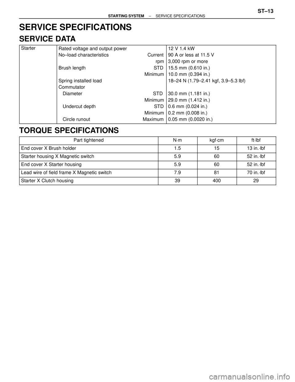
SERVICE SPECIFICATIONS
SERVICE DATA
������ �
����� �
����� �
����� �
����� �
����� �
����� �
����� �
����� �
����� ������
Starter���������������� �
��������������� �
��������������� �
��������������� �
��������������� �
��������������� �
��������������� �
��������������� �
��������������� �
��������������� ����������������
Rated voltage and output power
No±load characteristics Current
rpm
Brush length STD
Minimum
Spring installed load
Commutator
Diameter STD
Minimum
Undercut depth STD
Minimum
Circle runout Maximum���������������� �
��������������� �
��������������� �
��������������� �
��������������� �
��������������� �
��������������� �
��������������� �
��������������� �
��������������� ����������������
12 V 1.4 kW
90 A or less at 11.5 V
3,000 rpm or more
15.5 mm (0.610 in.)
10.0 mm (0.394 in.)
18±24 N (1.79±2.41 kgf, 3.9±5.3 lbf)
30.0 mm (1.181 in.)
29.0 mm (1.412 in.)
0.6 mm (0.024 in.)
0.2 mm (0.008 in.)
0.05 mm (0.0020 in.)
TORQUE SPECIFICATIONS
�������������������� ��������������������Part tightened������ ������NVm������ ������kgfVcm������� �������ftVlbf
�������������������� ��������������������End cover X Brush holder������ ������1.5������ ������15������� �������13 in.Vlbf
�������������������� ��������������������Starter housing X Magnetic switch������ ������5.9������ ������60������� �������52 in.Vlbf
�������������������� ��������������������End cover X Starter housing������ ������5.9������ ������60������� �������52 in.Vlbf�������������������� ��������������������Lead wire of field frame X Magnetic switch������ ������7.9������ ������81������� �������70 in.Vlbf�������������������� ��������������������Starter X Clutch housing������ ������39������ ������400������� �������29
± STARTING SYSTEMSERVICE SPECIFICATIONSST±13
Page 1647 of 2543
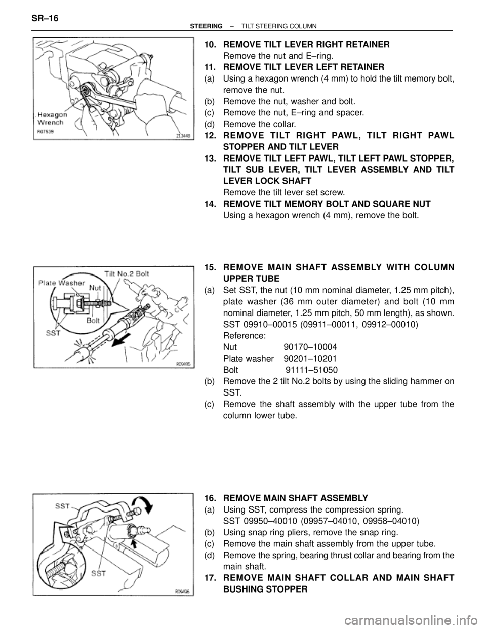
10. REMOVE TILT LEVER RIGHT RETAINER
Remove the nut and E±ring.
11. REMOVE TILT LEVER LEFT RETAINER
(a) Using a hexagon wrench (4 mm) to hold the tilt memory bolt,
remove the nut.
(b) Remove the nut, washer and bolt.
(c) Remove the nut, E±ring and spacer.
(d) Remove the collar.
12. R E M O V E T I LT R I G H T PAW L , T I LT R I G H T PAW L
STOPPER AND TILT LEVER
13. REMOVE TILT LEFT PAWL, TILT LEFT PAWL STOPPER,
TILT SUB LEVER, TILT LEVER ASSEMBLY AND TILT
LEVER LOCK SHAFT
Remove the tilt lever set screw.
14. REMOVE TILT MEMORY BOLT AND SQUARE NUT
Using a hexagon wrench (4 mm), remove the bolt.
15. RE MO V E MAIN SHAFT ASSEMBLY WITH COLUMN
UPPER TUBE
(a) Set SST, the nut (10 mm nominal diameter, 1.25 mm pitch),
plate washer (36 mm outer diameter) and bolt (10 mm
nominal diameter, 1.25 mm pitch, 50 mm length), as shown.
SST 09910±00015 (09911±00011, 09912±00010)
Reference:
Nut 90170±10004
Plate washer 90201±10201
Bolt 91111±51050
(b) Remove the 2 tilt No.2 bolts by using the sliding hammer on
SST.
(c) Remove the shaft assembly with the upper tube from the
column lower tube.
16. REMOVE MAIN SHAFT ASSEMBLY
(a) Using SST, compress the compression spring.
SST 09950±40010 (09957±04010, 09958±04010)
(b) Using snap ring pliers, remove the snap ring.
(c) Remove the main shaft assembly from the upper tube.
(d) Remove the spring, bearing thrust collar and bearing from the
main shaft.
17. RE MO V E MAIN SHAFT CO LLAR AND MAIN SHAFT
BUSHING STOPPER SR±16
± STEERINGTILT STEERING COLUMN