Page 1097 of 2543
RADIATOR REMOVAL
Installation is in the reverse order of removal.
1. REMOVE ENGINE UNDER COVER
INSTALLATION HINT: Start the engine, and check for cool-
ant and A/T fluid leaks.
2. REMOVE BATTERY AND BATTERY TRAY
3. DRAIN ENGINE COOLANT
4. 2JZ±GTE:
REMOVE NO.2 AIR TUBE
5. REMOVE NO.2 FAN SHROUD
(a) Remove the 2 clips.
(b) Disconnect the claw of the No.2 fan shroud from the hook of
the No.1 fan shroud, and remove the No.2 fan shroud.
6. REMOVE AIR CLEANER DUCT
7. 2JZ±GTE:
REMOVE NO.5 AIR HOSE
8. REMOVE LH HEADLIGHT BEAM ANGLE GAUGE
Remove the screw and beam angle gauge.
9. DISCONNECT HOSES FROM RADIATOR
Disconnect these hoses from the radiator:
(1) Reservoir inlet hose
(2) Upper radiator hose
(3) Lower radiator hose
(4) A/T:
2 oil cooler hoses
Plug the hose ends.
INSTALLATION HINT: Check the A/T fluid level.
(See item 21 in Maintenance) EG±346
± ENGINECOOLING SYSTEM
Page 1098 of 2543
 2JZ±GTE:
Disconnect the ECT switch (for electric cooling fan connec-
tor) and wire harness.
(b) 2JZ±GTE:
Disconnect the electric cooling fan connector and wire har-")
10. REMOVE RADIATOR ASSEMBLY
(a) 2JZ±GTE:
Disconnect the ECT switch (for electric cooling fan connec-
tor) and wire harness.
(b) 2JZ±GTE:
Disconnect the electric cooling fan connector and wire har-
ness.
(c) Remove the bolt and upper radiator support. Remove the 2
upper radiator supports.
INSTALLATION HINT: After installation, check that the rub-
ber cushion (A) of the support is not depressed.
Torque: 15 NVm (155 kgfVcm, 11 ftVlbf)
(d) Lift out the radiator assembly.
(e) Remove the 2 lower radiator supports.
11. REMOVE DRAIN HOSE FROM RADIATOR
12. 2JZ±GTE:
REMOVE ENGINE COOLANT TEMPERATURE (ECT)
SWITCH FROM RADIATOR
(a) Remove the ECT switch.
INSTALLATION HINT: Apply soapy water to the O±ring, and
install the ECT switch.
Torque: 7.4 NVm (75 kgfVcm, 65 in.Vlbf)
(b) Remove the O±ring from the ECT switch.
INSTALLATION HINT: Use a new O±ring.
13. 2JZ±GTE:
REMOVE ELECTRIC COOLING FAN FROM RADIATOR
Remove the 3 bolts and cooling fan.
14. REMOVE NO.1 FAN SHROUD FROM RADIATOR
Remove the 4 bolts and No.1 fan shroud.
± ENGINECOOLING SYSTEMEG±347
Page 1104 of 2543
ELECTRIC COOLING FAN (2JZ±GTE)
On±Vehicle Inspection
1. C H E C K C O O L I N G FA N O P E R AT I O N W I T H L O W
TEMPERATURE (Below 88°C (190°F))
(a) Turn the ignition switch ON.
(b) Check that the cooling fan stops.
If not, check the cooling fan relay and ECT switch, and check
for a separated connector or severed wire between the No.1
radiator fan relay and ECT switch.
(c) Disconnect the ECT switch connector.
(d) Check that the cooling fan rotates.
If not, check the No.1 radiator relay, No.2 radiator fan relay,
cooling fan, fuses, and check for short circuit between the
No.1 radiator fan relay and ECT switch.
(e) Reconnect the ECT switch connector.
2. CHECK COOLING FAN OPERATION WITH HIGH
TEMPERATURE (Above 97°C (207°F))
(a) Start the engine, and raise coolant temperature to above
97°C (207°F).
(b) Check that the cooling fan rotates.
If not, replace the ECT switch.
± ENGINECOOLING SYSTEMEG±353
Page 1107 of 2543

Switch
ECT SWITCH INSPECTION
1. REMOVE ENGINE UNDER COVER
2. DRAIN ENGINE COOLANT
3. REMOVE ECT SWITCH
(a) Disconnect the ECT switch connector.
(b) Remove the ECT")
Engine Coolant Temperature (ECT)
Switch
ECT SWITCH INSPECTION
1. REMOVE ENGINE UNDER COVER
2. DRAIN ENGINE COOLANT
3. REMOVE ECT SWITCH
(a) Disconnect the ECT switch connector.
(b) Remove the ECT switch.
(c) Remove the O±ring from the ECT switch.
4. INSPECT ECT SWITCH
(a) Usin g an oh mme te r, ch e ck th a t th e re is no co n tin u ity
between the terminals when the coolant temperature is
above 97°C (207°F).
(b) Using an ohmmeter, check that there is continuity between
the terminals when the coolant temperature is below 88°C
(190°F).
If continuity is not as specified, replace the switch.
5. REINSTALL ECT SWITCH
(a) Install a new O±ring to the ECT switch.
(b) Apply soapy water to the O±ring.
(c) Install the ECT switch.
Torque: 7.4 NVm (75 kgfVcm, 65 in.Vlbf)
(d) Connect the ECT switch connector.
6. REFILL WITH ENGINE COOLANT
7. START ENGINE AND CHECK FOR LEAKS
8. REINSTALL ENGINE UNDER COVER
No.1 Radiator Fan Relay
(ºRADIATOR FAN RELAYº)
RADIATOR FAN RELAY INSPECTION
1. w/ Auto Spoiler:
REMOVE LH HEADLIGHT
2. w/o Auto Spoiler:
REMOVE ENGINE UNDER COVER
3. REMOVE RADIATOR FAN RELAY
4. INSPECT RADIATOR FAN RELAY
A. Inspect relay continuity
(a) Using an ohmmeter, check that there is continuity between
terminals 3 and 4.
(b) Check that there is no continuity between terminals 1 and 2.
If continuity is as specified, replace the relay. EG±356
± ENGINECOOLING SYSTEM
Page 1116 of 2543

SYSTEM
EGR SYSTEM INSPECTION
1. CHECK AND CLEAN FILTER IN EGR VACUUM
MODULATOR
(a) Remove the cap and filter.
(b) Check the filter for contamination or damage.
(c)")
EXHAUST GAS RECIRCULATION (EGR)
SYSTEM
EGR SYSTEM INSPECTION
1. CHECK AND CLEAN FILTER IN EGR VACUUM
MODULATOR
(a) Remove the cap and filter.
(b) Check the filter for contamination or damage.
(c) Using compressed air, clean the filter.
(d) Reinstall the filter and cap.
HINT: Install the filter with the coarser surface facing the at-
mospheric side outward.
2. INSTALL VACUUM GAUGE
Using a 3±way connector, connect a vacuum gauge to the
hose between the EGR valve and EGR vacuum modulator.
3. INSPECT SEATING OF EGR VALVE
Check that the engine starts and runs at idle.
4. INSPECT VSV OPERATION WITH COLD ENGINE
(a) The engine coolant temperature should be below 45°C
(113°F).
(b) Check that the vacuum gauge indicates zero at 2,500 rpm.
(c) Check that the EGR pipe is not hot.
5. INSPECT OPERATION OF VSV AND EGR VACUUM
MODULATOR WITH HOT ENGINE
(a) Warm up the engine to above 50°C (122°F).
(b) Check that the vacuum gauge indicates low vacuum at 3,500
rpm.
(c) Disconnect the vacuum hose from port R of the EGR vacuum
modulator and connect port R directly to the air intake
chamber with another hose.
(d) Check that the vacuum gauge indicates high vacuum at
3,500 rpm.
HINT: As exhaust gas is increasingly recirculated, the engine
will start to misfire.
6. REMOVE VACUUM GAUGE
Remove the vacuum gauge, and reconnect the vacuum
hoses to their proper locations. EG±168
± ENGINEEMISSION CONTROL SYSTEMS (2JZ±GE)
Page 1129 of 2543

SYSTEM
EGR SYSTEM INSPECTION
1. INSPECT AND CLEAN FILTER IN EGR VACUUM
MODULATOR
(a) Remove the cap and 2 filters.
(b) Check the filter for contamination or damage.")
EXHAUST GAS RECIRCULATION (EGR)
SYSTEM
EGR SYSTEM INSPECTION
1. INSPECT AND CLEAN FILTER IN EGR VACUUM
MODULATOR
(a) Remove the cap and 2 filters.
(b) Check the filter for contamination or damage.
(c) Using compressed air, clean the filter.
(d) Reinstall the 2 filters and cap.
HINT: Install the filter with the coarser surface facing the at-
mospheric side (outward).
2. INSTALL VACUUM GAUGE
Using a 3±way connector, connect a vacuum gauge to the
hose between the EGR valve and vacuum modulator.
3. INSPECT SEATING OF EGR VALVE
Start the engine and check that the engine starts and runs at
at idle.
4. INSPECT VSV OPERATION WITH COLD ENGINE
(a) The coolant temperature should be below 50°C (122° F).
(b) From idle, race the engine to 3,500±4,000 rpm (throttle valve
opening angle to about 1/3 of maximum).
(c) Check that the EGR pipe is not hot.
(d) Check that the vacuum gauge indicates zero.
5. INSPECT VSV OPERATION WITH HOT ENGINE
(a) Warm up the engine to above 50°C (122°F)
(b) From idle, race the engine to 3,500±4,000 rpm (throttle valve
opening angle to about 1/3 of maximum).
(c) Check that the vacuum gauge indicates low vacuum.
6. REMOVE VACUUM GAUGE
Remove the vacuum gauge, and reconnect the vacuum
hoses to their proper locations.
7. INSPECT EGR VALVE
(a) Apply vacuum directly to the EGR valve with the engine
idling.
(b) Check that the engine runs rough or dies.
(c) Reconnect the vacuum hoses to the proper locations.
IF NO PROBLEM IS FOUND DURING THIS INSPECTION,
SYSTEM IS NORMAL; OTHERWISE INSPECT EACH
PART
VSV INSPECTION
(See VSV for EGR in SFI System) EG±180
± ENGINEEMISSION CONTROL SYSTEMS (2JZ±GTE)
Page 1138 of 2543
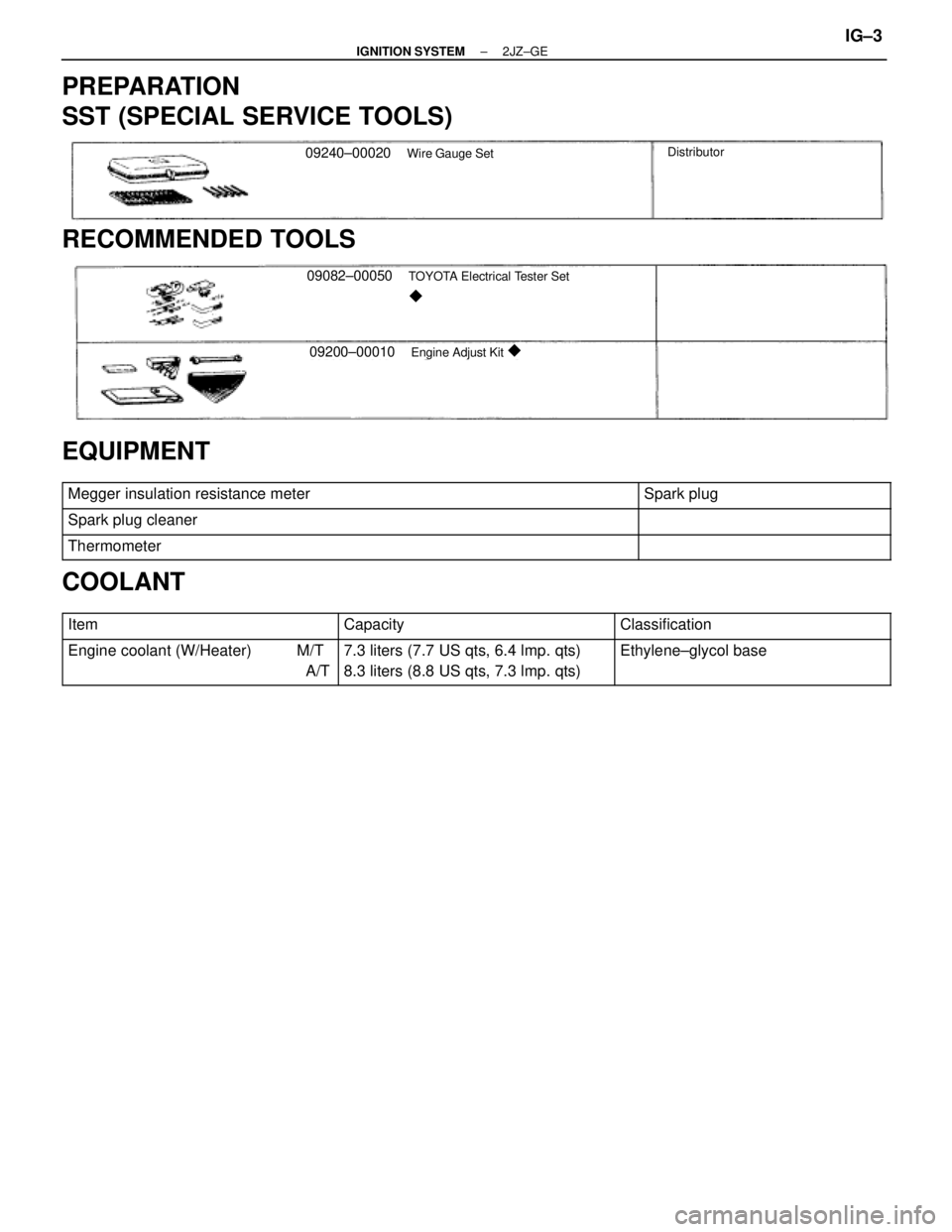
PREPARATION
SST (SPECIAL SERVICE TOOLS)
09240±00020Wire Gauge SetDistributor
RECOMMENDED TOOLS
09082±00050TOYOTA Electrical Tester Set
�
09200±00010Engine Adjust Kit �
EQUIPMENT
������������������������� �������������������������Megger insulation resistance meter������������ ������������Spark plug
������������������������� �������������������������Spark plug cleaner������������ ������������
������������������������� �������������������������Thermometer������������ ������������
COOLANT
������������� �������������Item������������ ������������Capacity������������� �������������Classification
������������� �
������������ �������������Engine coolant (W/Heater) M/T
A/T������������ �
����������� ������������7.3 liters (7.7 US qts, 6.4 lmp. qts)
8.3 liters (8.8 US qts, 7.3 lmp. qts)������������� �
������������ �������������Ethylene±glycol base
± IGNITION SYSTEM2JZ±GEIG±3
Page 1148 of 2543
(c) Secure the high±tension cords with the 8 cord clamps as
shown in the illustration.
2. INSTALL CYLINDER HEAD REAR COVER
3. INSTALL NO.3 TIMING BELT COVER
4. INSTALL THROTTLE BODY ASSEMBLY
(See throttle body installation in SFI System)
5. FILL WITH ENGINE COOLANT
± IGNITION SYSTEM(2JZ±GE)IG±13


On±Vehicle Inspection
1. C H E C K C O O L I N G FA N O P E R AT I O N W I T H L O W
TEMPERATURE (Below 88°C (190°F))
(a) Turn the ignition switch ON.
(b) Check th")
 Secure the high±tension cords with the 8 cord clamps as
shown in the illustration.
2. INSTALL CYLINDER HEAD REAR COVER
3. INSTALL NO.3 TIMING BELT COVER
4. INSTALL THROTTLE BODY ASSEMBLY
(See")