Page 1875 of 2543
UPPER SUSPENSION ARM REMOVAL
Installation is in the reverse order of removal.
INSTALLATION HINT: After installation, check ABS speed
sensor signal and rear wheel alignment.
(See page BR±62 and SA±9)
1. REMOVE REAR WHEEL
Torque: 103 NVm (1,050 kgfVcm, 76 ftVlbf)
2. REMOVE REAR DRIVE SHAFT
(See page SA±46)
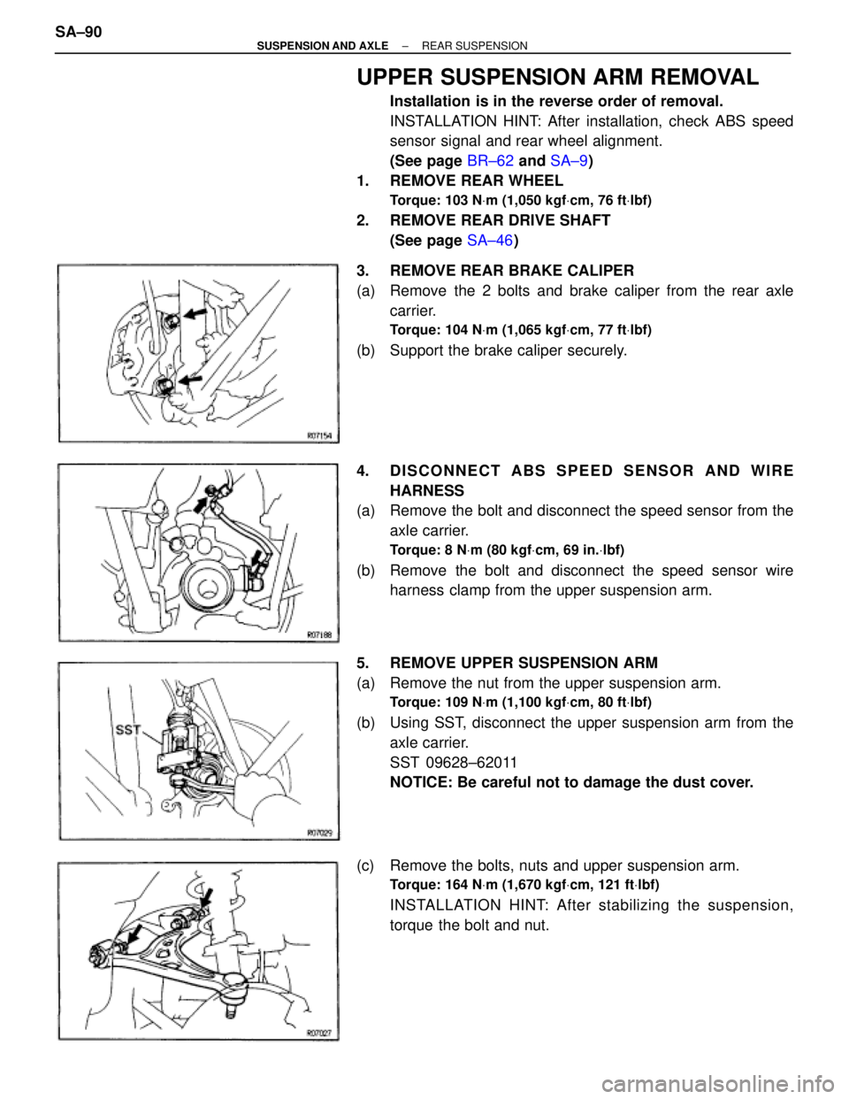
3. REMOVE REAR BRAKE CALIPER
(a) Remove the 2 bolts and brake caliper from the rear axle
carrier.
Torque: 104 NVm (1,065 kgfVcm, 77 ftVlbf)
(b) Support the brake caliper securely.
4. DISCONNECT ABS SPEED SENSOR AND WIRE
HARNESS
(a) Remove the bolt and disconnect the speed sensor from the
axle carrier.
Torque: 8 NVm (80 kgfVcm, 69 in.Vlbf)
(b) Remove the bolt and disconnect the speed sensor wire
harness clamp from the upper suspension arm.
5. REMOVE UPPER SUSPENSION ARM
(a) Remove the nut from the upper suspension arm.
Torque: 109 NVm (1,100 kgfVcm, 80 ftVlbf)
(b) Using SST, disconnect the upper suspension arm from the
axle carrier.
SST 09628±62011
NOTICE: Be careful not to damage the dust cover.
(c) Remove the bolts, nuts and upper suspension arm.
Torque: 164 NVm (1,670 kgfVcm, 121 ftVlbf)
INSTALLATION HINT: After stabilizing the suspension,
torque the bolt and nut. SA±90
± SUSPENSION AND AXLEREAR SUSPENSION
Page 1878 of 2543
LOWER SUSPENSION ARM AND STRUT
ROD REMOVAL
Installation is in the reverse order of removal.
INSTALLATION HINT: After installation, check ABS speed
sensor signal and rear wheel alignment.
(See page BR±62 and SA±9)
1. REMOVE REAR WHEEL
Torque: 103 NVm (1,050 kgfVcm, 76 ftVlbf)
2. REMOVE REAR DRIVE SHAFT
(See page SA±46)
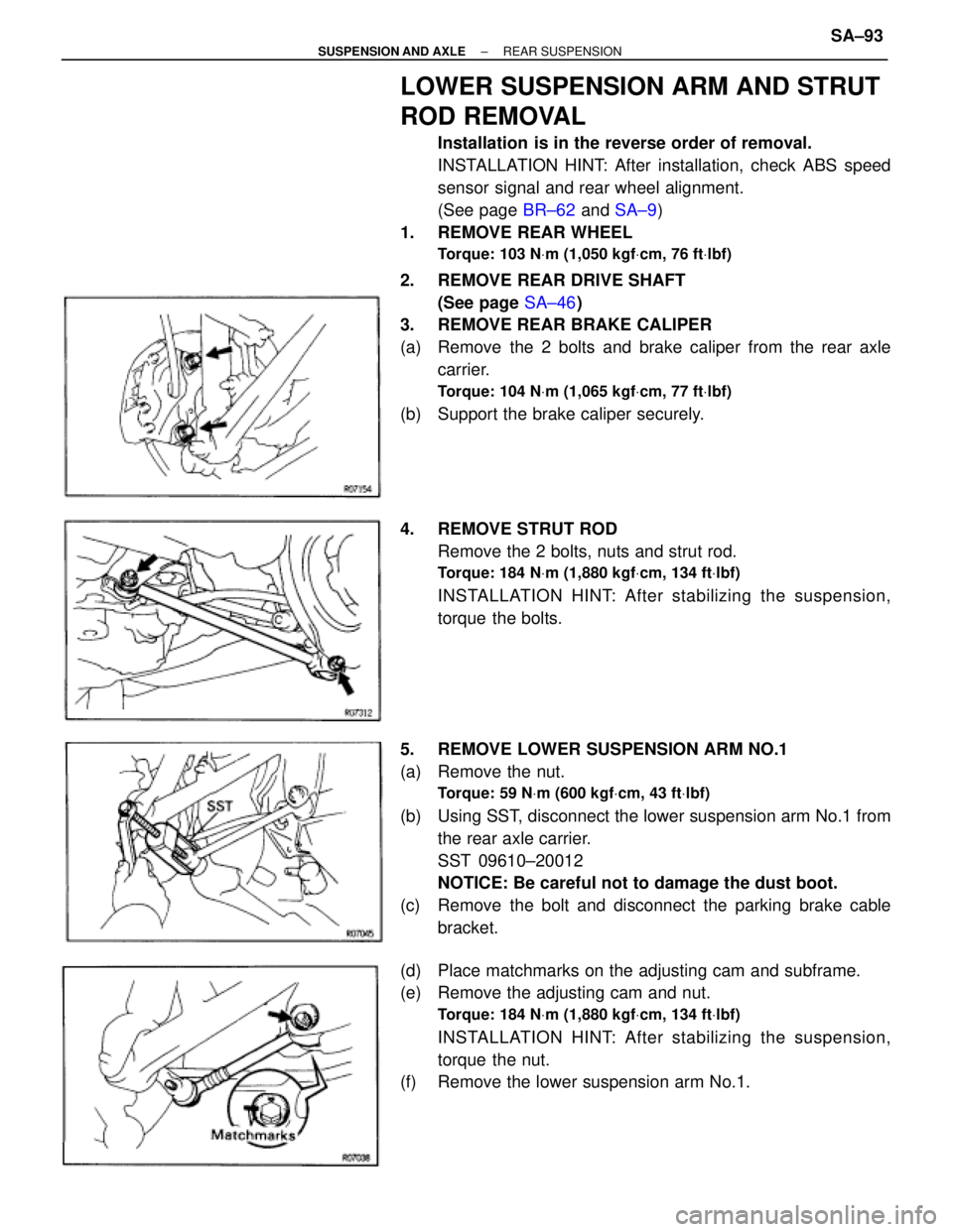
3. REMOVE REAR BRAKE CALIPER
(a) Remove the 2 bolts and brake caliper from the rear axle
carrier.
Torque: 104 NVm (1,065 kgfVcm, 77 ftVlbf)
(b) Support the brake caliper securely.
4. REMOVE STRUT ROD
Remove the 2 bolts, nuts and strut rod.
Torque: 184 NVm (1,880 kgfVcm, 134 ftVlbf)
INSTALLATION HINT: After stabilizing the suspension,
torque the bolts.
5. REMOVE LOWER SUSPENSION ARM NO.1
(a) Remove the nut.
Torque: 59 NVm (600 kgfVcm, 43 ftVlbf)
(b) Using SST, disconnect the lower suspension arm No.1 from
the rear axle carrier.
SST 09610±20012
NOTICE: Be careful not to damage the dust boot.
(c) Remove the bolt and disconnect the parking brake cable
bracket.
(d) Place matchmarks on the adjusting cam and subframe.
(e) Remove the adjusting cam and nut.
Torque: 184 NVm (1,880 kgfVcm, 134 ftVlbf)
INSTALLATION HINT: After stabilizing the suspension,
torque the nut.
(f) Remove the lower suspension arm No.1.
± SUSPENSION AND AXLEREAR SUSPENSIONSA±93
Page 1884 of 2543
Cold tire
inflation
pressure
Vehicle height
Front wheel
alignment
Front axle hub
Front
suspension
Rear wheel
alignment
Rear axle hub
Rear
suspension
Rear
drive shaft
Toe±in
Camber
Caster
Steering axis
inclination
Wheel angle
(Max.)
Tie rod end left±right error
Bearing axial direction play
Upper ball joint turning torque
Axle hub flange runout
Bearing axial direction play
Stabilizer bar link ball joint turning torque
Lower ball joint turning torque
Axle hub flange runout
Stabilizer bar link ball joint turning torque
Lower ball joint turning torque
Lower ball joint turning torque
Toe±in
Camber
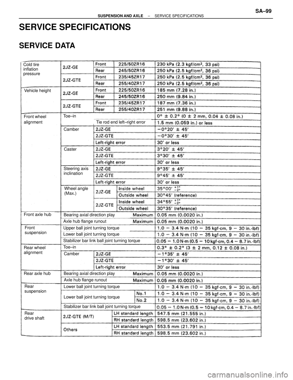
SERVICE SPECIFICATIONS
SERVICE DATA
± SUSPENSION AND AXLESERVICE SPECIFICATIONSSA±99