Page 548 of 2543

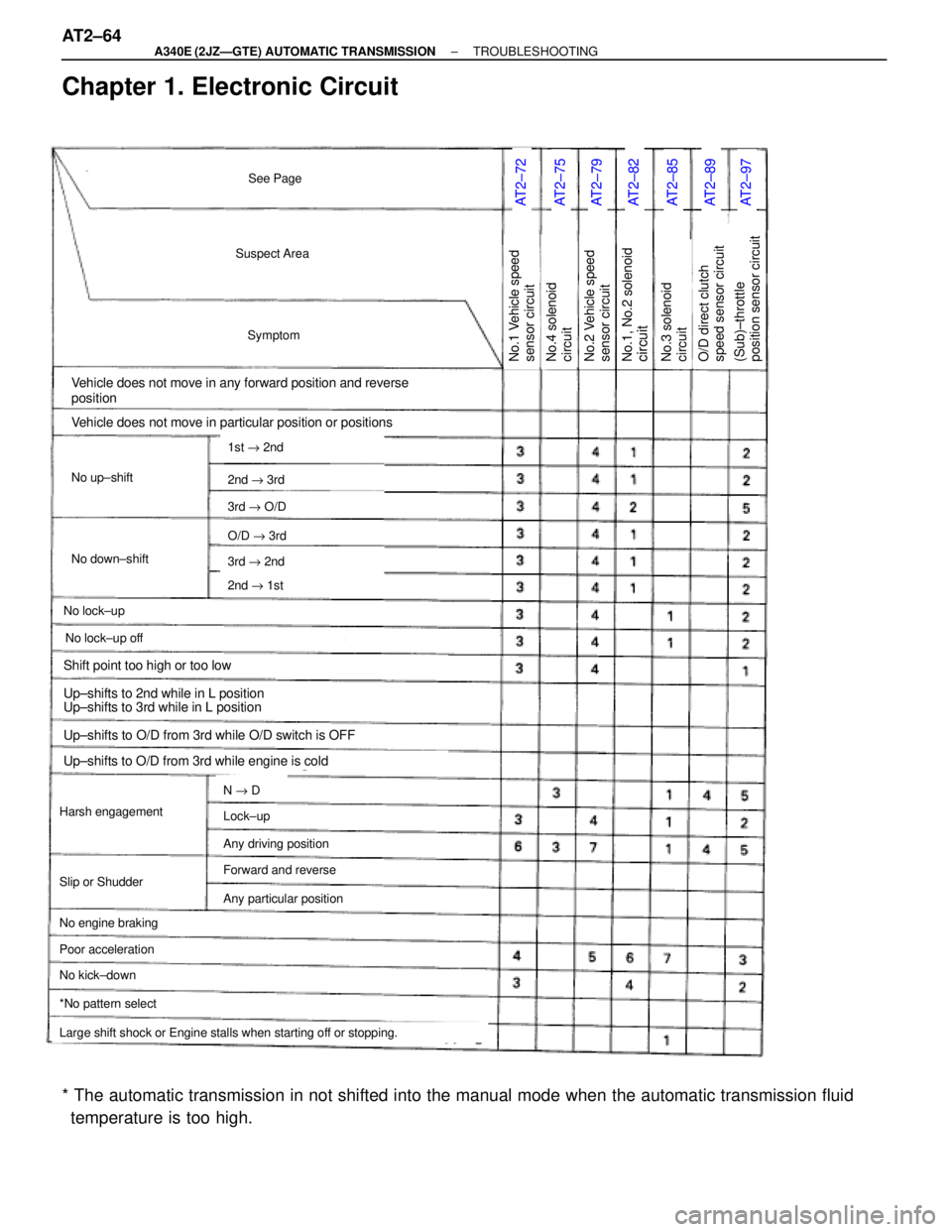
Chapter 1. Electronic Circuit
AT2±72AT2±75AT2±79AT2±82AT2±85AT2±89AT2±97
Suspect Area
Symptom
Vehicle does not move in any forward position and reverse
position
No up±shift
No down±shift
No lock±up
Vehicle does not move in particular position or positions
Harsh engagement
No engine braking
1st " 2nd
2nd " 3rd
3rd " O/D
O/D " 3rd
3rd " 2nd
2nd " 1st
N " D
Large shift shock or Engine stalls when starting off or stopping.
*No pattern select
No.1 Vehicle speed
sensor circuit
See Page
No lock±up off
Slip or Shudder
Poor acceleration
No kick±down
Lock±up
Any driving position
Forward and reverse
Any particular position
Shift point too high or too low
Up±shifts to 2nd while in L position
Up±shifts to 3rd while in L position
Up±shifts to O/D from 3rd while O/D switch is OFF
Up±shifts to O/D from 3rd while engine is cold
No.1, No.2 solenoidcircuitNo.2 Vehicle speed
sensor circuitNo.4 solenoid
circuitNo.3 solenoid
circuit(Sub)±throttle
position sensor circuitO/D direct clutch
speed sensor circuit
* The automatic transmission in not shifted into the manual mode when the automatic transmission fluid
temperature is too high. AT2±64
± A340E (2JZÐGTE) AUTOMATIC TRANSMISSIONTROUBLESHOOTING
Page 552 of 2543

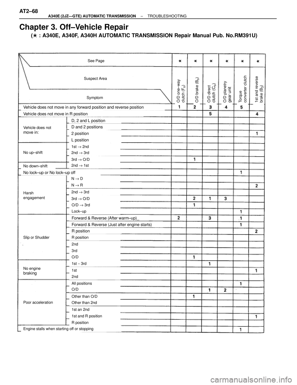
Suspect Area
Symptom
See Page
Vehicle does not move in any forward position and reverse position
No up±shift
No down±shift
Vehicle does not move in R position
1st " 2nd
2nd " 3rd
3rd " O/D
O/D " 3rd
3rd " O/D
2nd " 1st
2nd " 3rd
N " R
N " D
Lock±up
R position
2nd
3rd
1st ~ 3rd
O/D
1st
2nd
All positions
O/D
Other than O/D
Other than 2nd
1st an 2nd
R position
1st and R position
Engine stalls when starting off or stopping
Poor acceleration
No enginebraking
Slip or Shudder
Harsh
engagement
Vehicle does notmove in:
No lock±up or No lock±up off
Forward & Reverse (After warm±up)_
Forward & Reverse (Just after engine starts)
R position
D, 2 and L position
D and 2 positions
2 position
L position
O/D one±way
clutch (F
o)
O/D planetrygear unitO/D directclutch (C
o)
O/D brake (B
o)
1st and reverse
brake (B
3)
Torque
converter clutch
Chapter 3. Off±Vehicle Repair
(� : A340E, A340F, A340H AUTOMATIC TRANSMISSION Repair Manual Pub. No.RM391U) AT2±68
± A340E (2JZÐGTE) AUTOMATIC TRANSMISSIONTROUBLESHOOTING
Page 553 of 2543
2nd coast
brake (B
1)
Forward clutch
(C1)
Front and rear
planetary gear unitDirect clutch
(C2)
2nd brake (B
2)
No.2 one±way
clutch (F
2)
No.1 one±way
clutch (F
1)
± A340E (2JZÐGTE) AUTOMATIC TRANSMISSIONTROUBLESHOOTINGAT2±69
Page 559 of 2543

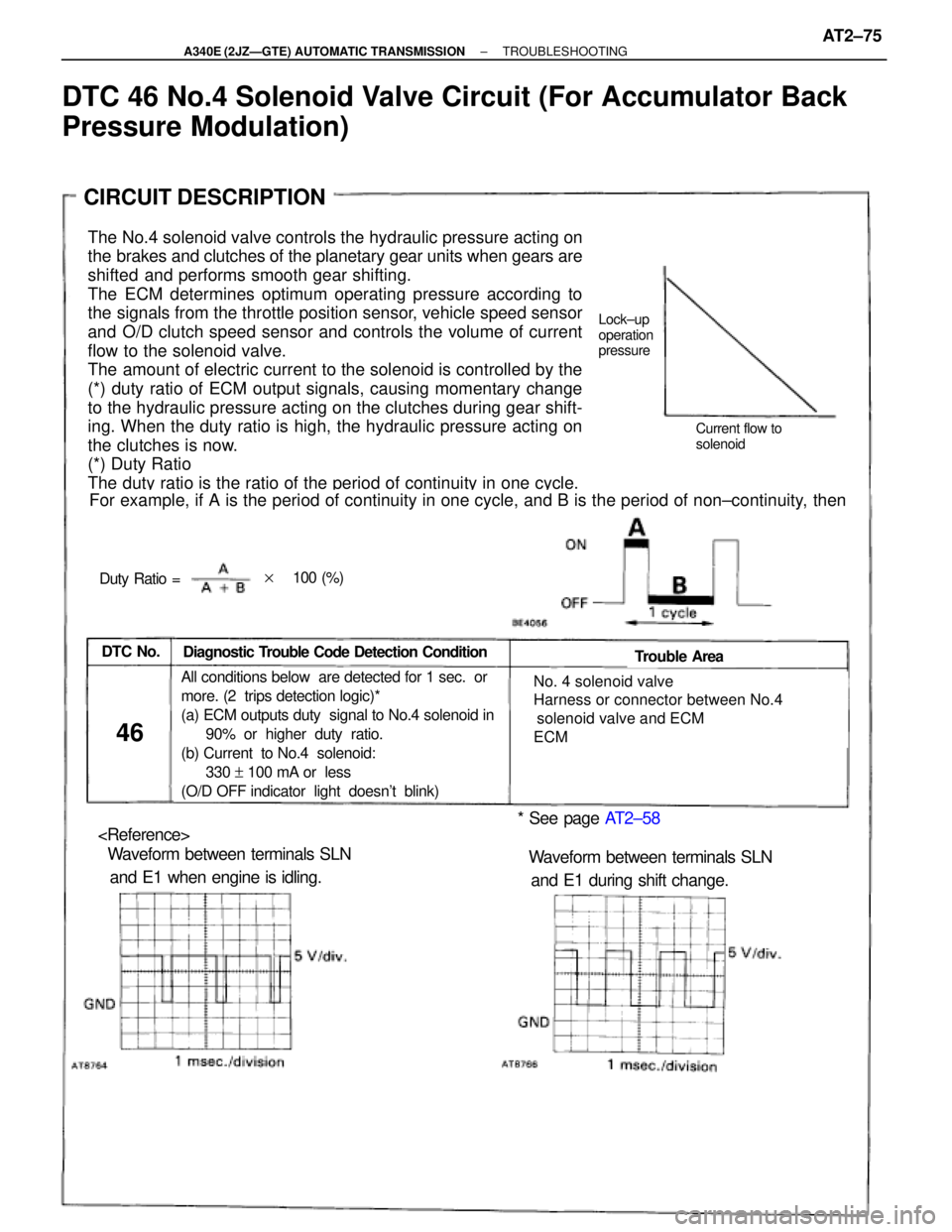
The No.4 solenoid valve controls the hydraulic pressure acting on
the brakes and clutches of the planetary gear units when gears are
shifted and performs smooth gear shifting.
The ECM determines optimum operating pressure according to
the signals from the throttle position sensor, vehicle speed sensor
and O/D clutch speed sensor and controls the volume of current
flow to the solenoid valve.
The amount of electric current to the solenoid is controlled by the
(*) duty ratio of ECM output signals, causing momentary change
to the hydraulic pressure acting on the clutches during gear shift-
ing. When the duty ratio is high, the hydraulic pressure acting on
the clutches is now.
(*) Duty Ratio
The duty ratio is the ratio of the period of continuity in one cycle.
For example, if A is the period of continuity in one cycle, and B is the period of non±continuity, then
Diagnostic Trouble Code Detection ConditionDTC No.Trouble Area
46
� No. 4 solenoid valve
� Harness or connector between No.4
solenoid valve and ECM
� ECMAll conditions below are detected for 1 sec. or
more. (2 trips detection logic)*
(a) ECM outputs duty signal to No.4 solenoid in
90% or higher duty ratio.
(b) Current to No.4 solenoid:
330 + 100 mA or less
(O/D OFF indicator light doesn't blink)
* See page AT2±58
� Waveform between terminals SLN
and E1 when engine is idling.� Waveform between terminals SLN
and E1 during shift change.
Lock±up
operation
pressure
Current flow to
solenoid
Duty Ratio =
CIRCUIT DESCRIPTION
��100 (%)
DTC 46 No.4 Solenoid Valve Circuit (For Accumulator Back
Pressure Modulation)
± A340E (2JZÐGTE) AUTOMATIC TRANSMISSIONTROUBLESHOOTINGAT2±75
Page 573 of 2543

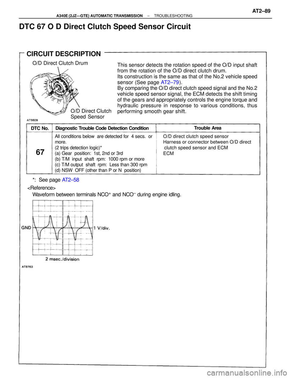
DTC No.Trouble Area
67
� O/D direct clutch speed sensor
� Harness or connector between O/D direct
clutch speed sensor and ECM
� ECMAll conditions below are detected for 4 secs. or
more.
(2 trips detection logic)*
(a) Gear position: 1st, 2nd or 3rd
(b) T/M input shaft rpm: 1000 rpm or more
(c) T/M output shaft rpm: Less than 300 rpm
(d) NSW OFF (other than P or N position)
Diagnostic Trouble Code Detection Condition
*: See page AT2±58
� Waveform between terminals NCO+ and NCO± during engine idling.
This sensor detects the rotation speed of the O/D input shaft
from the rotation of the O/D direct clutch drum.
Its construction is the same as that of the No.2 vehicle speed
sensor (See page AT2±79).
By comparing the O/D direct clutch speed signal and the No.2
vehicle speed sensor signal, the ECM detects the shift timing
of the gears and appropriately controls the engine torque and
hydraulic pressure in response to various conditions, thus
performing smooth gear shift.O/D Direct Clutch Drum
O/D Direct Clutch
Speed Sensor
CIRCUIT DESCRIPTION
DTC 67 O D Direct Clutch Speed Sensor Circuit
± A340E (2JZÐGTE) AUTOMATIC TRANSMISSIONTROUBLESHOOTINGAT2±89
Page 575 of 2543
Check O/D direct clutch speed sensor.
Remove the O/D direct clutch speed sensor from
the transmission (See page AT2±17).
Measure resistance between the terminals 1 and 2
of the O/D direct clutch speed sensor.
Resistance: 560 Ð 680 �
Check and repair harness and connector between
ECM and O/D direct clutch speed sensor (See page
IN±30).
Check the speed sensor function
Check voltage between the terminals 1 and 2 of
the speed sensor when a magnet is put close to
the front end of the speed sensor then taken away
quickly.
Voltage is generated intermittently.
The voltage generated is extremely low.
Replace O/D direct clutch speed sensor.
± A340E (2JZÐGTE) AUTOMATIC TRANSMISSIONTROUBLESHOOTINGAT2±91
Page 587 of 2543
Stop Light Switch Circuit
CIRCUIT DESCRIPTION
The purpose of this circuit is to prevent the engine from stalling, while driving in lock±up condition, when
brakes are suddenly applied.
When the brake pedal is operated, this switch sends a signal to the ECM. Then the ECM cancels operation
of the lock±up clutch while braking is in progress.
± A340E (2JZÐGTE) AUTOMATIC TRANSMISSIONTROUBLESHOOTINGAT2±103
Page 589 of 2543
Pattern Select Switch Circuit
CIRCUIT DESCRIPTION
The ECM memory contains the shift programs for the NORMAL and MANUAL patterns, 2 position, L posi-
tion and the lock±up patterns. Following the programs corresponding to the signals from the pattern select
switch, the park/neutral position switch and other various sensors the ECM switches the solenoid valves
ON and OFF, thereby controlling the transmission gear change and the lock±up clutch operation.
± A340E (2JZÐGTE) AUTOMATIC TRANSMISSIONTROUBLESHOOTINGAT2±105