Page 2038 of 2543
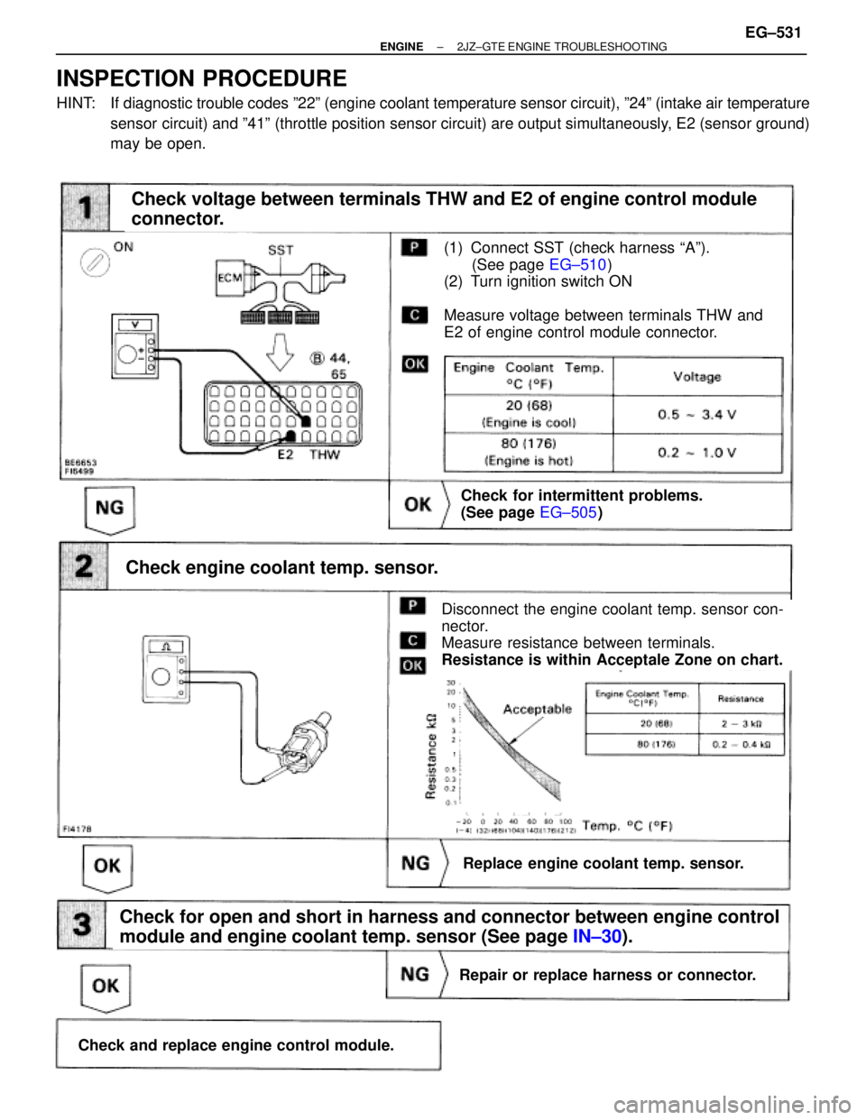
(See page EG±510)
(1) Connect SST (check harness ªAº).
(See page EG±510)
(2) Turn ignition switch ON
Measure voltage between terminals THW and
E2 of engine control module connector.
Check voltage between terminals THW and E2 of engine control module
connector.
Check for intermittent problems.
(See page EG±505)
Disconnect the engine coolant temp. sensor con-
nector.
Measure resistance between terminals.
Resistance is within Acceptale Zone on chart.
Check engine coolant temp. sensor.
Replace engine coolant temp. sensor.
Repair or replace harness or connector.
Check and replace engine control module.
Check for open and short in harness and connector between engine control
module and engine coolant temp. sensor (See page IN±30).
INSPECTION PROCEDURE
HINT: If diagnostic trouble codes º22º (engine coolant temperature sensor circuit), º24º (intake air temperature
sensor circuit) and º41º (throttle position sensor circuit) are output simultaneously, E2 (sensor ground)
may be open.
± ENGINE2JZ±GTE ENGINE TROUBLESHOOTINGEG±531
Page 2039 of 2543
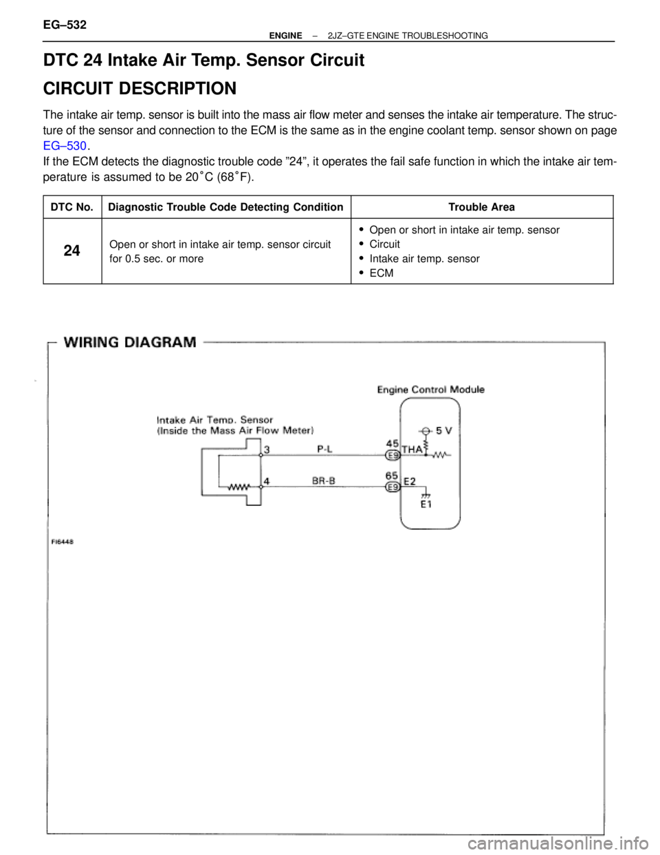
DTC 24 Intake Air Temp. Sensor Circuit
CIRCUIT DESCRIPTION
The intake air temp. sensor is built into the mass air flow meter and senses the intake air temperature. The struc-
ture of the sensor and connection to the ECM is the same as in the engine coolant temp. sensor shown on page
EG±530.
If the ECM detects the diagnostic trouble code º24º, it operates the fail safe function in which the intake air tem-
perature is assumed to be 20°C (68°F).
����� �
���� �����DTC No.
���������������� �
��������������� ����������������Diagnostic Trouble Code Detecting Condition
���������������� �
���������������
����������������
Trouble Area
����� �
���� �
���� �
���� �����
24
���������������� �
��������������� �
��������������� �
��������������� ����������������
Open or short in intake air temp. sensor circuit
for 0.5 sec. or more
���������������� �
���������������
����������������
����������������
����������������
�Open or short in intake air temp. sensor
�Circuit
�Intake air temp. sensor
�ECM
EG±532± ENGINE2JZ±GTE ENGINE TROUBLESHOOTING
Page 2040 of 2543
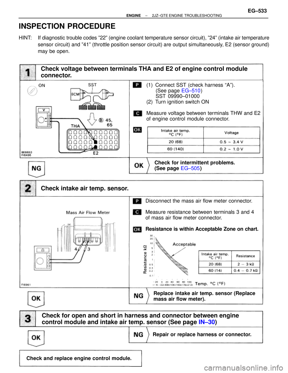
(See page EG±510)
(1) Connect SST (check harness ªAº).
(See page EG±510)
SST 09990±01000
(2) Turn ignition switch ON
Measure voltage between terminals THW and E2
of engine control module connector.
Check voltage between terminals THA and E2 of engine control module
connector.
Check for intermittent problems.
(See page EG±505)
Disconnect the mass air flow meter connector.
Measure resistance between terminals 3 and 4
of mass air flow meter connector.
Resistance is within Acceptable Zone on chart.
Check intake air temp. sensor.
Check for open and short in harness and connector between engine
control module and intake air temp. sensor (See page IN±30)
Replace intake air temp. sensor (Replace
mass air flow meter).
Repair or replace harness or connector.
Check and replace engine control module.
INSPECTION PROCEDURE
HINT: If diagnostic trouble codes º22º (engine coolant temperature sensor circuit), º24º (intake air temperature
sensor circuit) and º41º (throttle position sensor circuit) are output simultaneously, E2 (sensor ground)
may be open.
± ENGINE2JZ±GTE ENGINE TROUBLESHOOTINGEG±533
Page 2041 of 2543
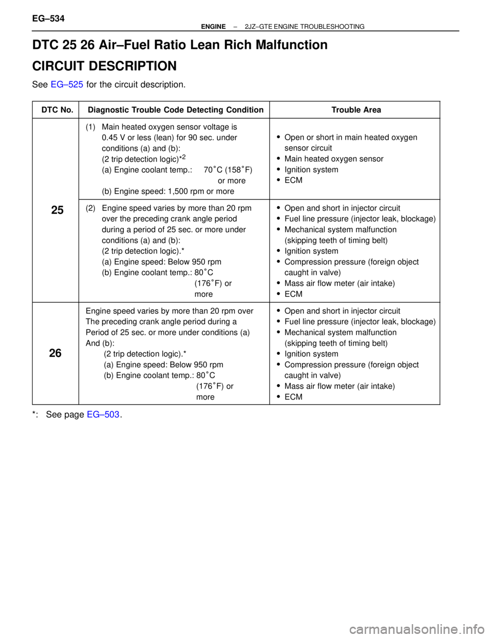
DTC 25 26 Air±Fuel Ratio Lean Rich Malfunction
CIRCUIT DESCRIPTION
See EG±525 for the circuit description.
����� �����DTC No.���������������� ����������������Diagnostic Trouble Code Detecting Condition��������������� ���������������Trouble Area
����� �
���� �
���� �
���� �
���� �
���� �
���� �����
���������������� �
��������������� �
��������������� �
��������������� �
��������������� �
��������������� �
��������������� ����������������
(1) Main heated oxygen sensor voltage is
0.45 V or less (lean) for 90 sec. under
conditions (a) and (b):
(2 trip detection logic)*
2
(a) Engine coolant temp.: 70°C (158°F)
or more
(b) Engine speed: 1,500 rpm or more
��������������� �
�������������� �
�������������� �
�������������� �
�������������� �
�������������� �
�������������� ���������������
�Open or short in main heated oxygen
sensor circuit
�Main heated oxygen sensor
�Ignition system
�ECM
����� �
���� �
���� �
���� �
���� �
���� �
���� �
���� �����
25���������������� �
��������������� �
��������������� �
��������������� �
��������������� �
��������������� �
��������������� �
��������������� ����������������
(2) Engine speed varies by more than 20 rpm
over the preceding crank angle period
during a period of 25 sec. or more under
conditions (a) and (b):
(2 trip detection logic).*
(a) Engine speed: Below 950 rpm
(b) Engine coolant temp.: 80°C
(176°F) or
more��������������� �
�������������� �
�������������� �
�������������� �
�������������� �
�������������� �
�������������� �
�������������� ���������������
�Open and short in injector circuit
�Fuel line pressure (injector leak, blockage)
�Mechanical system malfunction
(skipping teeth of timing belt)
�Ignition system
�Compression pressure (foreign object
caught in valve)
�Mass air flow meter (air intake)
�ECM
����� �
���� �
���� �
���� �
���� �
���� �
���� �
���� �����
26
���������������� �
��������������� �
��������������� �
��������������� �
��������������� �
��������������� �
��������������� �
��������������� ����������������
Engine speed varies by more than 20 rpm over
The preceding crank angle period during a
Period of 25 sec. or more under conditions (a)
And (b):
(2 trip detection logic).*
(a) Engine speed: Below 950 rpm
(b) Engine coolant temp.: 80°C
(176°F) or
more��������������� �
�������������� �
�������������� �
�������������� �
�������������� �
�������������� �
�������������� �
�������������� ���������������
�Open and short in injector circuit
�Fuel line pressure (injector leak, blockage)
�Mechanical system malfunction
(skipping teeth of timing belt)
�Ignition system
�Compression pressure (foreign object
caught in valve)
�Mass air flow meter (air intake)
�ECM
*: See page EG±503. EG±534
± ENGINE2JZ±GTE ENGINE TROUBLESHOOTING
Page 2045 of 2543
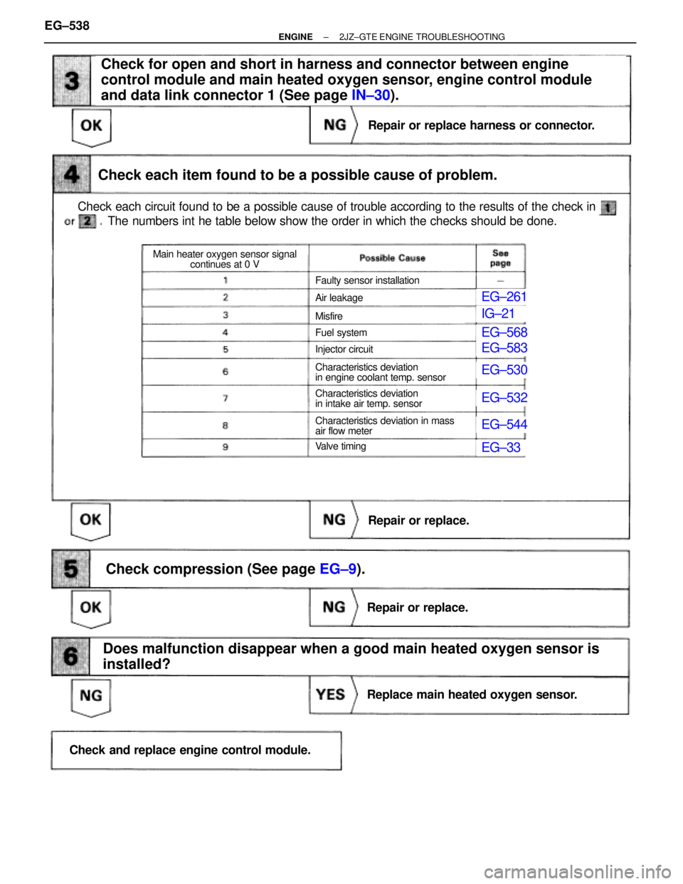
(See page EG±9).
EG±261
IG±21
EG±568
EG±583
EG±530
EG±532
EG±544
EG±33
Check each circuit found to be a possible cause of trouble according to the results of the check in
Check each item found to be a possible cause of problem.
Check for open and short in harness and connector between engine
control module and main heated oxygen sensor, engine control module
and data link connector 1 (See page IN±30).
The numbers int he table below show the order in which the checks should be done.
Repair or replace harness or connector.
Repair or replace.
Replace main heated oxygen sensor.
Repair or replace.
Check and replace engine control module.
Check compression (See page EG±9).
Does malfunction disappear when a good main heated oxygen sensor is
installed?
Faulty sensor installation
Air leakage
Misfire
Fuel system
Injector circuit
Characteristics deviation
in engine coolant temp. sensor
Characteristics deviation
in intake air temp. sensor
Characteristics deviation in mass
air flow meter
Va l v e t i m i n g
Main heater oxygen sensor signal
continues at 0 V
EG±538± ENGINE2JZ±GTE ENGINE TROUBLESHOOTING
Page 2046 of 2543
EG±583
IG±21
EG±33
EG±261
EG±568
EG±544
EG±530
EG±532
EG±9).
Check each circuit found to be a possible cause of trouble according to the results of the check in
Check each item found to be a possible cause of problem.
The numbers int he table below show the order in which the checks should be done.
Air leakage
Misfire
Fuel system
Injector circuit
Characteristics deviation
in engine coolant temp. sensor
Characteristics deviation
in intake air temp. sensor
Characteristics deviation in mass
air flow meter
Va l v e t i m i n g
Main heater oxygen sensor signal
continues at 5.0 VMain heater oxygen sensor
signal is normal
Check compression (See page EG±9).
Repair or replace.
Repair or replace.
Repair main heated oxygen sensor.
Check and replace engine control module.
Does malfunction disappear when a good main heated oxygen sensor is
installed?
± ENGINE2JZ±GTE ENGINE TROUBLESHOOTINGEG±539
Page 2047 of 2543
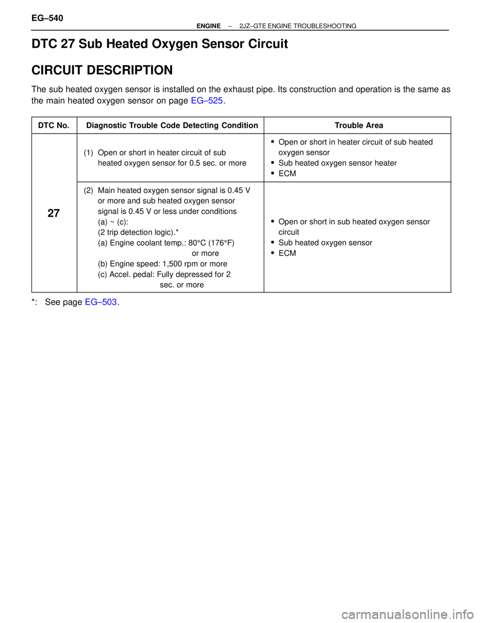
DTC 27 Sub Heated Oxygen Sensor Circuit
CIRCUIT DESCRIPTION
The sub heated oxygen sensor is installed on the exhaust pipe. Its construction and operation is the same as
the main heated oxygen sensor on page EG±525.
����� �
���� �����DTC No.���������������� �
��������������� ����������������Diagnostic Trouble Code Detecting Condition����������������� �
���������������� �����������������Trouble Area
����� �
���� �
���� �
���� �����
���������������� �
��������������� �
��������������� �
��������������� ����������������
(1) Open or short in heater circuit of sub
heated oxygen sensor for 0.5 sec. or more
����������������� �
���������������� �
���������������� �
���������������� �����������������
�Open or short in heater circuit of sub heated
oxygen sensor
�Sub heated oxygen sensor heater
�ECM
����� �
���� �
���� �
���� �
���� �
���� �
���� �
���� �
���� �����
27
���������������� �
��������������� �
��������������� �
��������������� �
��������������� �
��������������� �
��������������� �
��������������� �
��������������� ����������������
(2) Main heated oxygen sensor signal is 0.45 V
or more and sub heated oxygen sensor
signal is 0.45 V or less under conditions
(a) ~ (c):
(2 trip detection logic).*
(a) Engine coolant temp.: 805C (1765F)
or more
(b) Engine speed: 1,500 rpm or more
(c) Accel. pedal: Fully depressed for 2
sec. or more����������������� �
���������������� �
���������������� �
���������������� �
���������������� �
���������������� �
���������������� �
���������������� �
���������������� �����������������
�Open or short in sub heated oxygen sensor
circuit
�Sub heated oxygen sensor
�ECM
*: See page EG±503. EG±540
± ENGINE2JZ±GTE ENGINE TROUBLESHOOTING
Page 2061 of 2543
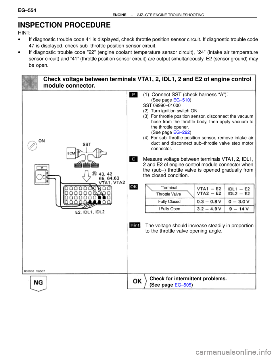
INSPECTION PROCEDURE
HINT:
wIf diagnostic trouble code 41 is displayed, check throttle position sensor circuit. If diagnostic trouble code
47 is displayed, check sub±throttle position sensor circuit.
wIf diagnostic trouble code º22º (engine coolant temperature sensor circuit), º24º (intake air temperature
sensor circuit) and º41º (throttle position sensor circuit) are output simultaneously. E2 (sensor ground) may
be open.
(See page EG±505)
(See page EG±510)
(See page EG±292)
Check voltage between terminals VTA1, 2, IDL1, 2 and E2 of engine control
module connector.
The voltage should increase steadily in proportion
to the throttle valve opening angle.
(1) Connect SST (check harness ªAº).
(See page EG±510)
SST 09990±01000
(2) Turn ignition switch ON.
(3) For throttle position sensor, disconnect the vacuum
hose from the throttle body, then apply vacuum to
the throttle opener.
(See page EG±292)
(4) For sub±throttle position sensor, remove intake air
duct and disconnect sub±throttle valve step motor
connector.
Measure voltage between terminals VTA1, 2, IDL1,
2 and E2 of engine control module connector when
the (sub±) throttle valve is opened gradually from
the closed condition.
Check for intermittent problems.
(See page
EG±505)
Throttle Valve
Terminal
Fully Closed
Fully Open
EG±554± ENGINE2JZ±GTE ENGINE TROUBLESHOOTING