Page 748 of 2248
G4M0398
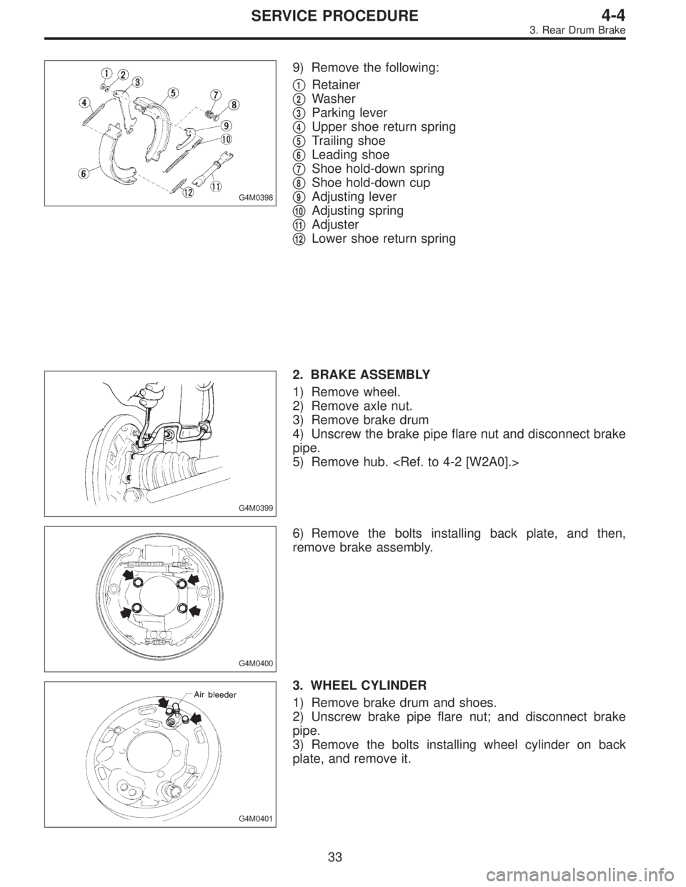
9) Remove the following:
�
1Retainer
�
2Washer
�
3Parking lever
�
4Upper shoe return spring
�
5Trailing shoe
�
6Leading shoe
�
7Shoe hold-down spring
�
8Shoe hold-down cup
�
9Adjusting lever
�
10Adjusting spring
�
11Adjuster
�
12Lower shoe return spring
G4M0399
2. BRAKE ASSEMBLY
1) Remove wheel.
2) Remove axle nut.
3) Remove brake drum
4) Unscrew the brake pipe flare nut and disconnect brake
pipe.
5) Remove hub.
G4M0400
6) Remove the bolts installing back plate, and then,
remove brake assembly.
G4M0401
3. WHEEL CYLINDER
1) Remove brake drum and shoes.
2) Unscrew brake pipe flare nut; and disconnect brake
pipe.
3) Remove the bolts installing wheel cylinder on back
plate, and remove it.
33
4-4SERVICE PROCEDURE
3. Rear Drum Brake
Page 752 of 2248

G4M0411
�1Back plate
�
2Retainer
�
3Spring washer
�
4Lever
�
5Parking brake shoe (Primary)
�
6Parking brake show (Secondary)
�
7Strut spring�
8Strut
�
9Shoe guide pl")
4. Parking Brake (Rear Disc Brake)
G4M0411
�1Back plate
�
2Retainer
�
3Spring washer
�
4Lever
�
5Parking brake shoe (Primary)
�
6Parking brake show (Secondary)
�
7Strut spring�
8Strut
�
9Shoe guide plate
�
10Primary return spring
�
11Secondary return spring
�
12Adjusting spring
�
13Adjuster
�
14Shoe hold-down cup�
15Shoe hold down spring
�
16Shoe hold down pin
�
17Adjusting hole cover
Tightening torque: N⋅m (kg-m, ft-lb)
T: 52±6 (5.3±0.6, 38.3±4.3)
G4M0412
A: REMOVAL
1) Remove the two mounting bolts to the disc brake
assembly and remove the disc brake assembly.
2) Suspend the disc brake assembly so that the hose is
not stretched.
3) Remove the disc rotor.
4) Remove shoe return spring from parking brake assem-
bly.
5) Remove front shoe hold down spring and pin with pli-
ers.
6) Remove strut and strut spring.
7) Remove adjuster assembly from parking brake assem-
bly.
8) Remove brake shoe.
9) Remove rear shoe hold-down spring and pin with pliers.
37
4-4SERVICE PROCEDURE
4. Parking Brake (Rear Disc Brake)
Page 753 of 2248
 Remove parking cable from parking lever.
11) Using a standard screwdriver, raise retainer. Remove
parking lever and washer from brake shoe.
B: INSPECTION
1) Measure brake disc inside diame")
G4M0413
10) Remove parking cable from parking lever.
11) Using a standard screwdriver, raise retainer. Remove
parking lever and washer from brake shoe.
B: INSPECTION
1) Measure brake disc inside diameter. If the disc is scored
or worn, replace the brake disc.
Disc inside diameter:
Standard
170 mm (6.69 in)
Service limit
171 mm (6.73 in)
2) Measure the lining thickness. If it exceeds the limit,
replace shoe assembly.
Lining thickness:
Standard
3.2 mm (0.126 in)
Service limit
1.5 mm (0.059 in)
CAUTION:
Replace the brake shoes on the right and left brake
assembly at the same time.
C: INSTALLATION
CAUTION:
Be sure lining surface is free from oil contamination.
Brake grease:
Dow Corning Molykote No 7439 (Part No.
725191460)
1) Apply brake grease to the following places.
�Six contact surfaces of shoe rim and back plate
packing
�Contact surface of shoe wave and anchor pin
�Contact surface of lever and strut
�Contact surface of shoe wave and adjuster assem-
bly
�Contact surface of shoe wave and strut
�Contact surface of lever and shoe wave
38
4-4SERVICE PROCEDURE
4. Parking Brake (Rear Disc Brake)
Page 754 of 2248
 Installation is in reverse order of removal.
CAUTION:
�Use new retainers and clinch them when installing
brake shoes to levers.
�Ensure that parking lever moves smoothly.
�Do not confuse left parki")
2) Installation is in reverse order of removal.
CAUTION:
�Use new retainers and clinch them when installing
brake shoes to levers.
�Ensure that parking lever moves smoothly.
�Do not confuse left parking lever with right one.
�Do not confuse left strut with right one.
G4M0414
NOTE:
Ensure that adjuster assembly is securely installed with
screw in the left side, facing vehicle front.
G4M0415
NOTE:
Ensure that shoe return spring is installed as shown in
Figure.
3) Adjust parking brakes.
CAUTION:
After replacing parking brake lining, be sure to drive
vehicle for“break-in”purposes.
(1) Drive the vehicle about 35 km/h (22 MPH).
(2) With the parking brake release button pushed in,
pull the parking brake lever gently, pulling with a force
of approximately 147 N (15 kg, 33 lb).
(3) Drive the vehicle for about 200 m (0.12 mile) in this
condition.
(4) Wait 5 to 10 minutes for the parking brake to cool
down. Repeat this procedure once more.
(5) After breaking-in, re-adjust parking brakes.
39
4-4SERVICE PROCEDURE
4. Parking Brake (Rear Disc Brake)
Page 755 of 2248
 Remove adjusting hole cover from back plate.
2) Turn adjusting screw using a slot-type screwdriver until
brake shoe is in close cont")
G4M0416
D: PARKING BRAKE ADJUSTMENT
1. SHOE CLEARANCE ADJUSTMENT
1) Remove adjusting hole cover from back plate.
2) Turn adjusting screw using a slot-type screwdriver until
brake shoe is in close contact with disc rotor.
3) Turn back (downward) adjusting screw 3 or 4 notches.
4) Install adjusting hole cover to back plate.
B4M0050A
2. LEVER STROKE ADJUSTMENT
1) Remove console box lid.
2) Forcibly pull parking brake lever 3 to 5 times.
3) Adjust parking brake lever by turning adjusting nut until
parking brake lever stroke is set at 6 notches with operat-
ing force of 196 N (20 kg, 44 lb).
4) Tighten lock nut.
5) Install console box lid.
Lever stroke:
7 to 8 notches when pulled
with a force of 196 N (20 kg, 44 lb)
Tightening torque (Lock nut):
5.9±1.5 N⋅m (0.60±0.15 kg-m, 4.3±1.1 ft-lb)
5. Master Cylinder
A: REMOVAL
1) Thoroughly drain brake fluid from reservoir tank.
2) Disconnect fluid level indicator harness connector.
3) Remove brake pipes from master cylinder.
4) Remove master cylinder mounting nuts, and take out
master cylinder from brake booster.
CAUTION:
Be extremely careful not to spill brake fluid. Brake fluid
spilt on the vehicle body will harm the painted surface;
wipe it off quickly if spilt.
40
4-4SERVICE PROCEDURE
4. Parking Brake (Rear Disc Brake) - 5. Master Cylinder
Page 756 of 2248
 Remove adjusting hole cover from back plate.
2) Turn adjusting screw using a slot-type screwdriver until
brake shoe is in close cont")
G4M0416
D: PARKING BRAKE ADJUSTMENT
1. SHOE CLEARANCE ADJUSTMENT
1) Remove adjusting hole cover from back plate.
2) Turn adjusting screw using a slot-type screwdriver until
brake shoe is in close contact with disc rotor.
3) Turn back (downward) adjusting screw 3 or 4 notches.
4) Install adjusting hole cover to back plate.
B4M0050A
2. LEVER STROKE ADJUSTMENT
1) Remove console box lid.
2) Forcibly pull parking brake lever 3 to 5 times.
3) Adjust parking brake lever by turning adjusting nut until
parking brake lever stroke is set at 6 notches with operat-
ing force of 196 N (20 kg, 44 lb).
4) Tighten lock nut.
5) Install console box lid.
Lever stroke:
7 to 8 notches when pulled
with a force of 196 N (20 kg, 44 lb)
Tightening torque (Lock nut):
5.9±1.5 N⋅m (0.60±0.15 kg-m, 4.3±1.1 ft-lb)
5. Master Cylinder
A: REMOVAL
1) Thoroughly drain brake fluid from reservoir tank.
2) Disconnect fluid level indicator harness connector.
3) Remove brake pipes from master cylinder.
4) Remove master cylinder mounting nuts, and take out
master cylinder from brake booster.
CAUTION:
Be extremely careful not to spill brake fluid. Brake fluid
spilt on the vehicle body will harm the painted surface;
wipe it off quickly if spilt.
40
4-4SERVICE PROCEDURE
4. Parking Brake (Rear Disc Brake) - 5. Master Cylinder
Page 768 of 2248
G4M0429
NOTE:
Whenever turning adjusting nut, prevent PHV cable from
revolving as shown in Figure.
9. Parking Brake Lever
A: REPLACEMENT
1) Remove console box from front floor.
2) Disconnect electric connector for parking brake switch.
3) Loosen parking brake adjuster, and remove inner cable
end from equalizer.
4) Remove parking brake lever.
5) Install parking brake lever in the reverse order of
removal.
Tightening torque (Lever installing bolt and nut):
18±5 N⋅m (1.8±0.5 kg-m, 13.0±3.6 ft-lb)
B4M0050A
6) Adjust parking brake lever by turning adjusting nut until
parking brake lever stroke is set at 7 to 8 notches with
operating force of 196 N (20 kg, 44 lb).
7) Tighten lock nut.
Tightening torque (Lock nut):
5.9±1.5 N⋅m (0.60±0.15 kg-m, 4.3±1.1 ft-lb)
52
4-4SERVICE PROCEDURE
8. Hill Holder - 9. Parking Brake Lever
Page 769 of 2248
G4M0429
NOTE:
Whenever turning adjusting nut, prevent PHV cable from
revolving as shown in Figure.
9. Parking Brake Lever
A: REPLACEMENT
1) Remove console box from front floor.
2) Disconnect electric connector for parking brake switch.
3) Loosen parking brake adjuster, and remove inner cable
end from equalizer.
4) Remove parking brake lever.
5) Install parking brake lever in the reverse order of
removal.
Tightening torque (Lever installing bolt and nut):
18±5 N⋅m (1.8±0.5 kg-m, 13.0±3.6 ft-lb)
B4M0050A
6) Adjust parking brake lever by turning adjusting nut until
parking brake lever stroke is set at 7 to 8 notches with
operating force of 196 N (20 kg, 44 lb).
7) Tighten lock nut.
Tightening torque (Lock nut):
5.9±1.5 N⋅m (0.60±0.15 kg-m, 4.3±1.1 ft-lb)
52
4-4SERVICE PROCEDURE
8. Hill Holder - 9. Parking Brake Lever
 Remove console box from front floor.
2) Disconnect electric")
 Remove console box from front floor.
2) Disconnect electric")