Page 1272 of 2248
�When mounting a large power type radio, pay spe-
cial attention to the three items above mentioned.
�Incorrect installation of the radio may affect the
operation of the ECM.
8) Before disconnecting the fuel hose, disconnect the fuel
pump connector and crank the engine for more than five
seconds to release pressure in the fuel system. If engine
starts during this operation, run it until it stops.
9) Problems in the electronic-controlled automatic trans-
mission may be caused by failure of the engine, the elec-
tronic control system, the transmission proper, or by a com-
bination of these. These three causes must be distin-
guished clearly when performing diagnostics.
10) Diagnostics should be conducted by rotating with
simple, easy operations and proceeding to complicated,
difficult operations. The most important thing in diagnostics
is to understand the customer’s complaint, and distinguish
between the three causes.
11) In AT vehicles, do not continue the stall for more than
five seconds at a time (from closed throttle, fully open
throttle to stall engine speed).
12) On ABS or ABS/TCS vehicle, when performing driving
test in jacked-up or lifted-up position, sometimes the warn-
ing light may be lit, but this is not a malfunction of the sys-
tem. The reason for this is the speed difference between
the front and rear wheels. After diagnosis of engine control
system, perform the ABS or ABS/TCS memory clearance
procedure of self-diagnosis system.
4-4b [T6C2] or [T9K0].>
C: PRE-INSPECTION
Before performing diagnostics, check the following items
which might affect engine problems:
1. POWER SUPPLY
1) Measure battery voltage and specific gravity of electro-
lyte.
Standard voltage: 12 V
Specific gravity: Above 1.260
2) Check the condition of the main and other fuses, and
harnesses and connectors. Also check for proper ground-
ing.
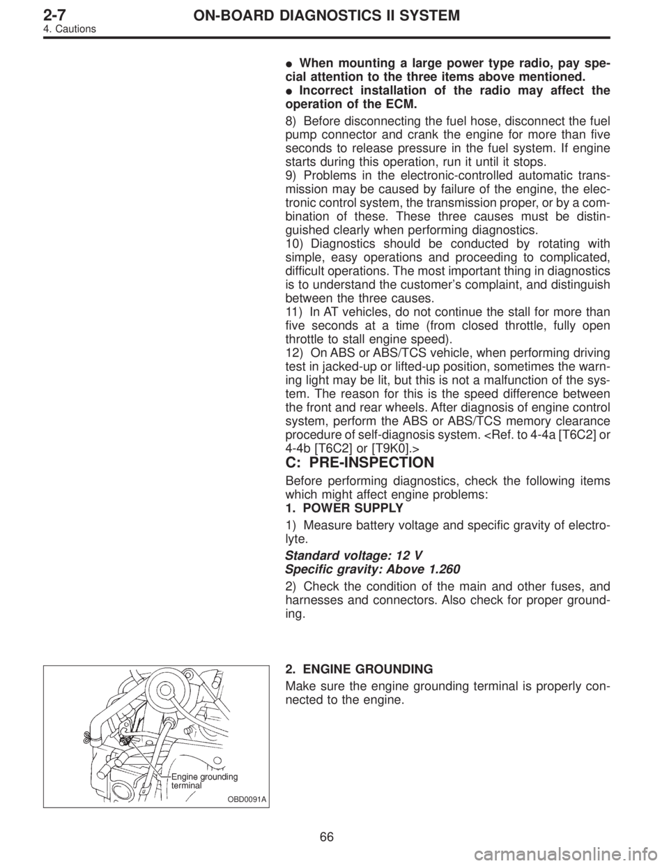
OBD0091A
2. ENGINE GROUNDING
Make sure the engine grounding terminal is properly con-
nected to the engine.
66
2-7ON-BOARD DIAGNOSTICS II SYSTEM
4. Cautions
Page 1275 of 2248
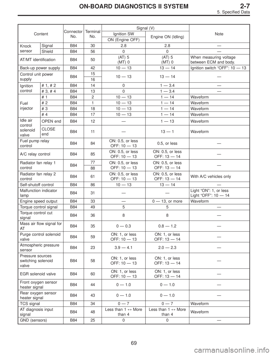
ContentConnector
No.Terminal
No.Signal (V)
Note Ignition SW
Engine ON (Idling)
ON (Engine OFF)
Knock
sensorSignal B84 30 2.8 2.8—
Shield B84 56 0 0—
AT/MT identification B84 50(AT) 5
(MT) 0(AT) 5
(MT) 0When measuring voltage
between ECM and body.
Back-up power supply B84 42 10—13 13—14 Ignition switch“OFF”:10—13
Control unit power
supplyB8415
10—13 13—14—
16
Ignition
control#1,#2 B84 14 0 1—3.4—
#3,#4 B84 13 0 1—3.4—
Fuel
injector# 1 B84 2 10—13 1—14 Waveform
# 2 B84 1 10—13 1—14 Waveform
# 3 B84 18 10—13 1—14 Waveform
# 4 B84 17 10—13 1—14 Waveform
Idle air
control
solenoid
valveOPEN end B84 12—1—13 Waveform
CLOSE
endB84 11—13—1 Waveform
Fuel pump relay
controlB84 84ON: 0.5, or less
OFF: 10—130.5, or less—
A/C relay control B84 85ON: 0.5, or less
OFF: 10—13ON: 0.5, or less
OFF: 13—14—
Radiator fan relay 1
controlB8477
ON: 0.5, or less
OFF: 10—13ON: 0.5, or less
OFF: 13—14—
88
Radiator fan relay 2
controlB84 61ON: 0.5, or less
OFF: 10—13ON: 0.5, or less
OFF: 13—14With A/C vehicles only
Self-shutoff control B84 86 10—13 13—14—
Malfunction indicator
lampB84 31——Light“ON”: 1, or less
Light“OFF”:10—14
Engine speed output B84 33—0—13, or more Waveform
Torque control signal B84 49 5 5—
Torque control cut
signalB84 36 8 8—
Mass air flow signal for
ATB84 35 0—0.3 0.8—1.2—
Purge control solenoid
valveB84 59ON: 1, or less
OFF: 10—13ON: 1, or less
OFF: 13—14—
Atmospheric pressure
sensorB84 23 3.9—4.1 2.0—2.3—
Pressure sources
switching solenoid
valveB84 58ON: 1, or less
OFF: 10—13ON: 1, or less
OFF: 13—14—
EGR solenoid valve B84 60ON: 1, or less
OFF: 10—13ON: 1, or less
OFF: 13—14—
Front oxygen sensor
heater signalB84 44 0—1.0 0—1.0—
Rear oxygen sensor
heater signalB84 43 0—1.0 0—1.0—
TCS signal B84 34 0—70—7 Waveform
AT diagnosis input
signalB84 48Less than 1)More
than 4Less than 1)More
than 4Waveform
GND (sensors) B84 25 0 0—
69
2-7ON-BOARD DIAGNOSTICS II SYSTEM
5. Specified Data
Page 1313 of 2248
9. Diagnostics for Engine Starting
Failure
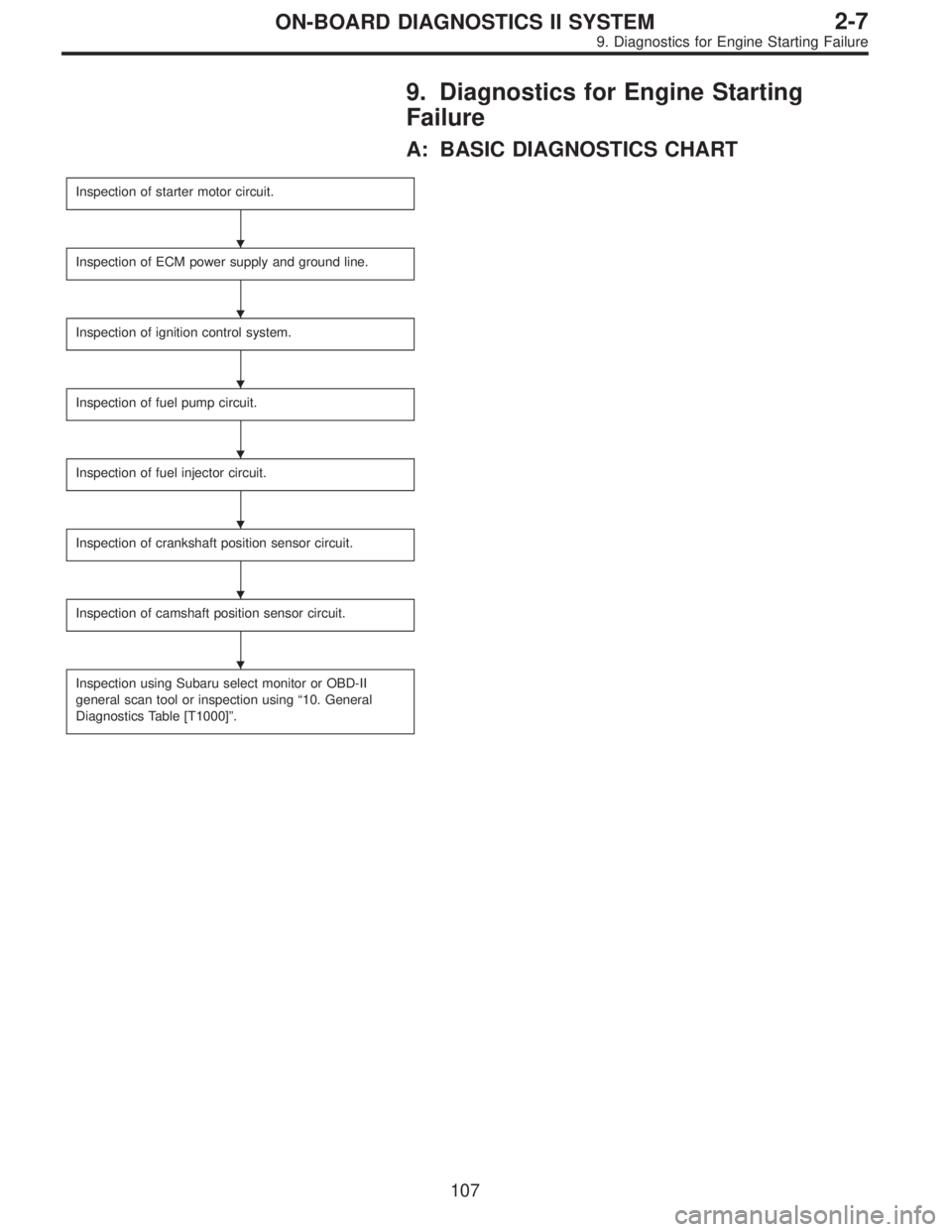
A: BASIC DIAGNOSTICS CHART
Inspection of starter motor circuit.
Inspection of ECM power supply and ground line.
Inspection of ignition control system.
Inspection of fuel pump circuit.
Inspection of fuel injector circuit.
Inspection of crankshaft position sensor circuit.
Inspection of camshaft position sensor circuit.
Inspection using Subaru select monitor or OBD-II
general scan tool or inspection using“10. General
Diagnostics Table [T1000]”.
�
�
�
�
�
�
�
107
2-7ON-BOARD DIAGNOSTICS II SYSTEM
9. Diagnostics for Engine Starting Failure
Page 1323 of 2248
OBD0727
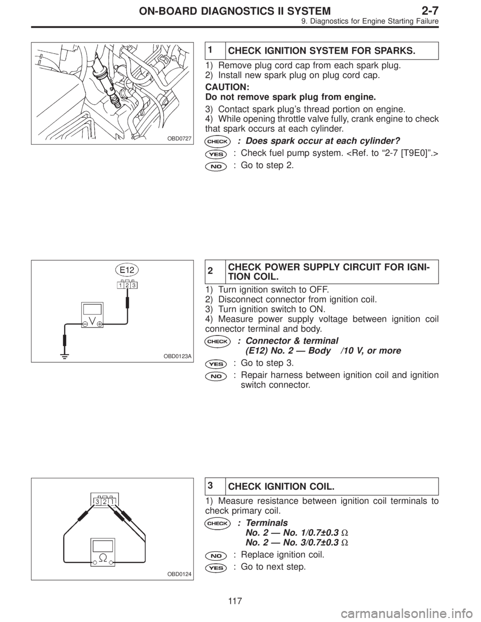
1
CHECK IGNITION SYSTEM FOR SPARKS.
1) Remove plug cord cap from each spark plug.
2) Install new spark plug on plug cord cap.
CAUTION:
Do not remove spark plug from engine.
3) Contact spark plug’s thread portion on engine.
4) While opening throttle valve fully, crank engine to check
that spark occurs at each cylinder.
: Does spark occur at each cylinder?
: Check fuel pump system.
: Go to step 2.
OBD0123A
2CHECK POWER SUPPLY CIRCUIT FOR IGNI-
TION COIL.
1) Turn ignition switch to OFF.
2) Disconnect connector from ignition coil.
3) Turn ignition switch to ON.
4) Measure power supply voltage between ignition coil
connector terminal and body.
: Connector & terminal
(E12) No. 2—Body /10 V, or more
: Go to step 3.
: Repair harness between ignition coil and ignition
switch connector.
OBD0124
3
CHECK IGNITION COIL.
1) Measure resistance between ignition coil terminals to
check primary coil.
: Terminals
No. 2—No. 1/0.7±0.3Ω
No. 2—No. 3/0.7±0.3Ω
: Replace ignition coil.
: Go to next step.
11 7
2-7ON-BOARD DIAGNOSTICS II SYSTEM
9. Diagnostics for Engine Starting Failure
Page 1326 of 2248
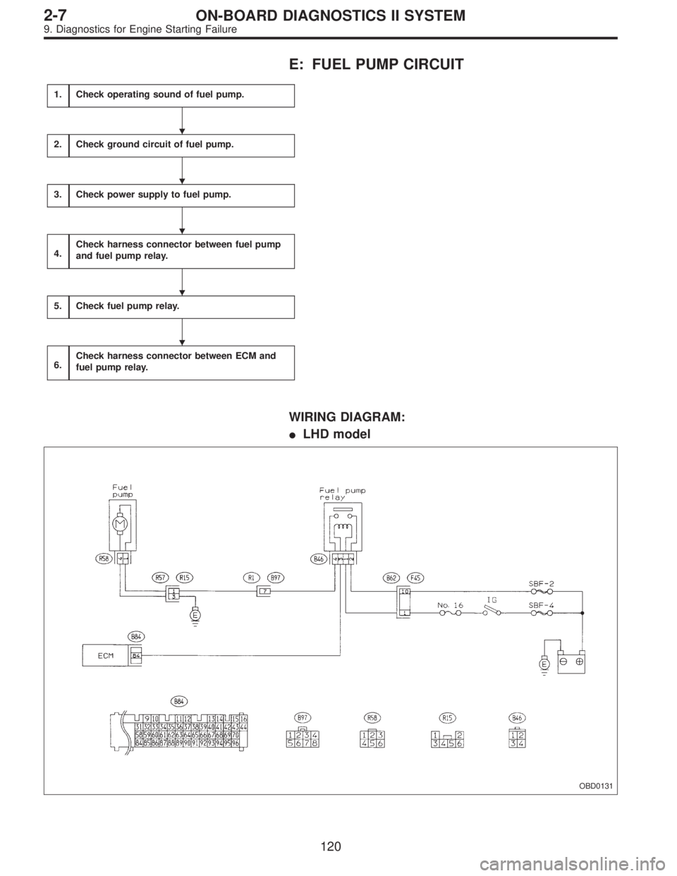
E: FUEL PUMP CIRCUIT
1.Check operating sound of fuel pump.
2.Check ground circuit of fuel pump.
3.Check power supply to fuel pump.
4.Check harness connector between fuel pump
and fuel pump relay.
5.Check fuel pump relay.
6.Check harness connector between ECM and
fuel pump relay.
WIRING DIAGRAM:
�LHD model
OBD0131
�
�
�
�
�
120
2-7ON-BOARD DIAGNOSTICS II SYSTEM
9. Diagnostics for Engine Starting Failure
Page 1328 of 2248
1
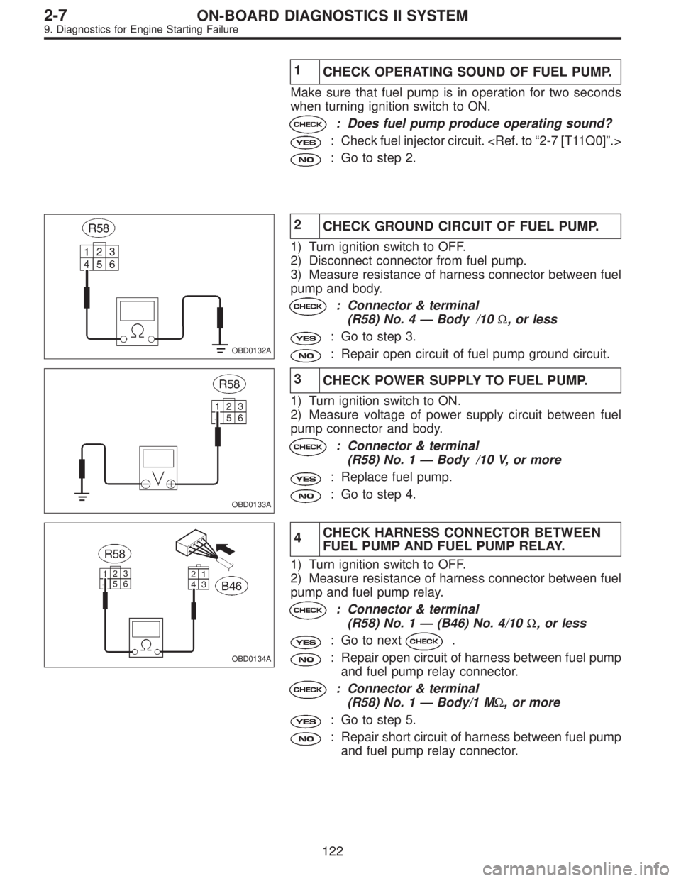
CHECK OPERATING SOUND OF FUEL PUMP.
Make sure that fuel pump is in operation for two seconds
when turning ignition switch to ON.
: Does fuel pump produce operating sound?
: Check fuel injector circuit.
: Go to step 2.
OBD0132A
2
CHECK GROUND CIRCUIT OF FUEL PUMP.
1) Turn ignition switch to OFF.
2) Disconnect connector from fuel pump.
3) Measure resistance of harness connector between fuel
pump and body.
: Connector & terminal
(R58) No. 4—Body /10Ω, or less
: Go to step 3.
: Repair open circuit of fuel pump ground circuit.
OBD0133A
3
CHECK POWER SUPPLY TO FUEL PUMP.
1) Turn ignition switch to ON.
2) Measure voltage of power supply circuit between fuel
pump connector and body.
: Connector & terminal
(R58) No. 1—Body /10 V, or more
: Replace fuel pump.
: Go to step 4.
OBD0134A
4CHECK HARNESS CONNECTOR BETWEEN
FUEL PUMP AND FUEL PUMP RELAY.
1) Turn ignition switch to OFF.
2) Measure resistance of harness connector between fuel
pump and fuel pump relay.
: Connector & terminal
(R58) No. 1—(B46) No. 4/10Ω, or less
: Go to next.
: Repair open circuit of harness between fuel pump
and fuel pump relay connector.
: Connector & terminal
(R58) No. 1—Body/1 MΩ, or more
: Go to step 5.
: Repair short circuit of harness between fuel pump
and fuel pump relay connector.
122
2-7ON-BOARD DIAGNOSTICS II SYSTEM
9. Diagnostics for Engine Starting Failure
Page 1329 of 2248
G2M0461
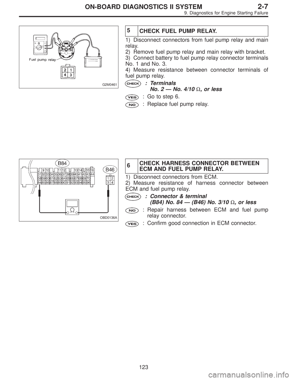
5
CHECK FUEL PUMP RELAY.
1) Disconnect connectors from fuel pump relay and main
relay.
2) Remove fuel pump relay and main relay with bracket.
3) Connect battery to fuel pump relay connector terminals
No. 1 and No. 3.
4) Measure resistance between connector terminals of
fuel pump relay.
: Terminals
No. 2—No. 4/10Ω, or less
: Go to step 6.
: Replace fuel pump relay.
OBD0136A
6CHECK HARNESS CONNECTOR BETWEEN
ECM AND FUEL PUMP RELAY.
1) Disconnect connectors from ECM.
2) Measure resistance of harness connector between
ECM and fuel pump relay.
: Connector & terminal
(B84) No. 84—(B46) No. 3/10Ω, or less
: Repair harness between ECM and fuel pump
relay connector.
: Confirm good connection in ECM connector.
123
2-7ON-BOARD DIAGNOSTICS II SYSTEM
9. Diagnostics for Engine Starting Failure
Page 1334 of 2248
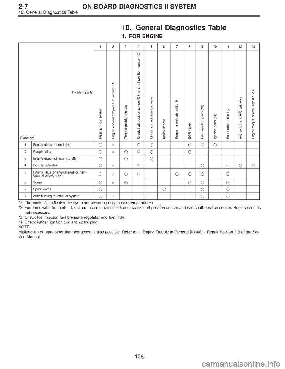
10. General Diagnostics Table
1. FOR ENGINE
12345678910111213
Problem parts
Mass air flow sensor
Engine coolant temperature sensor (*1)
Throttle position sensor
Crankshaft position sensor & Camshaft position sensor (*2)
Idle air control solenoid valve
Knock sensor
Purge control solenoid valve
EGR valve
Fuel injection parts (*3)
Ignition parts (*4)
Fuel pump and relay
A/C switch and A/C cut relay
Engine torque control signal circuitSymptom
1 Engine stalls during idling.�� � � ���
2 Rough idling�� � � � �
3 Engine does not return to idle.���
4 Poor acceleration�� � � ���
5Engine stalls or engine sags or hesi-
tates at acceleration.�� � � ��� �
6 Surge�� � �� �
7 Spark knock����
8 After burning in exhaust system�� � �
*1: The mark,�, indicates the symptom occurring only in cold temperatures.
*2: For items with the mark,�, ensure the secure installation of crankshaft position sensor and camshaft position sensor. Replacement is
not necessary.
*3: Check fuel injector, fuel pressure regulator and fuel filter.
*4: Check igniter, ignition coil and spark plug.
NOTE:
Malfunction of parts other than the above is also possible. Refer to 1. Engine Trouble in General [K100] in Repair Section 2-3 of the Ser-
vice Manual.
128
2-7ON-BOARD DIAGNOSTICS II SYSTEM
10. General Diagnostics Table