Page 202 of 2248
C: INSTALLATION
CAUTION:
�If fuel hoses are damaged at the connecting portion,
replace it with a new one.
�If clamps are badly damaged, replace with new ones.
G2M0347
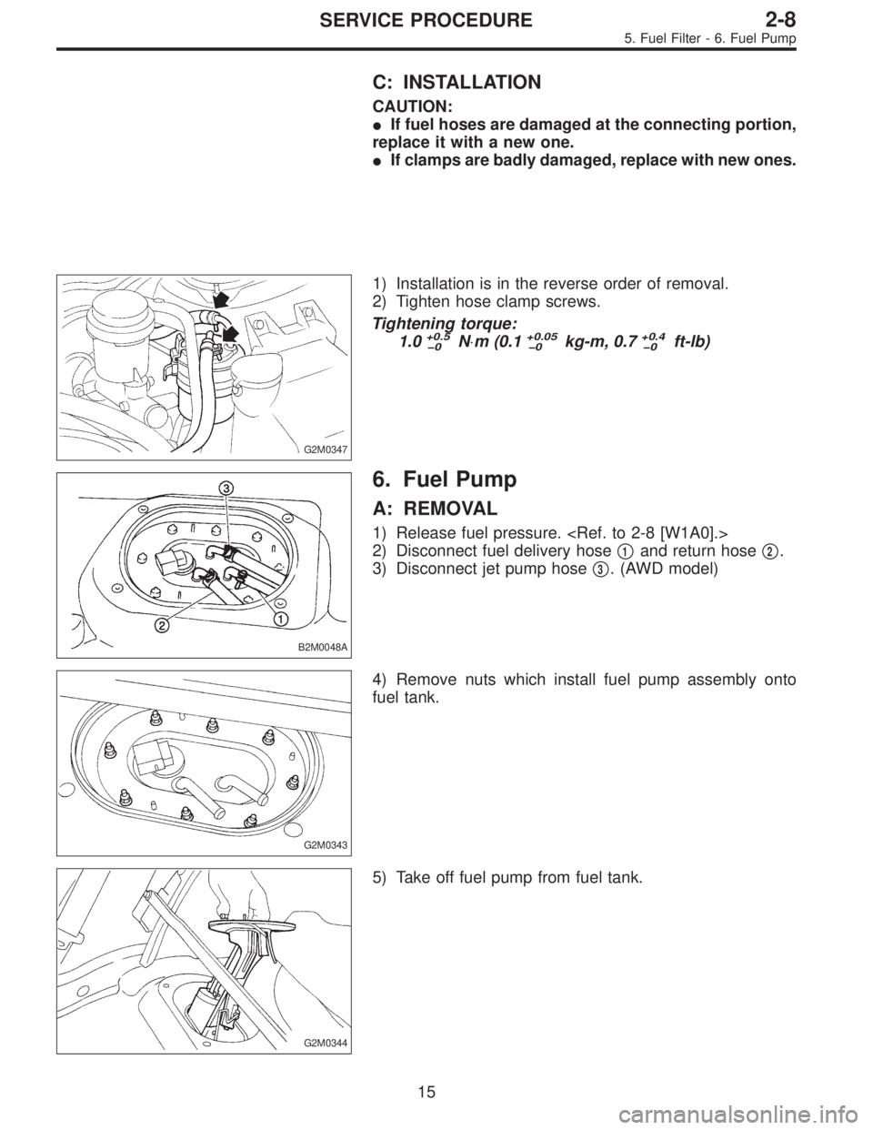
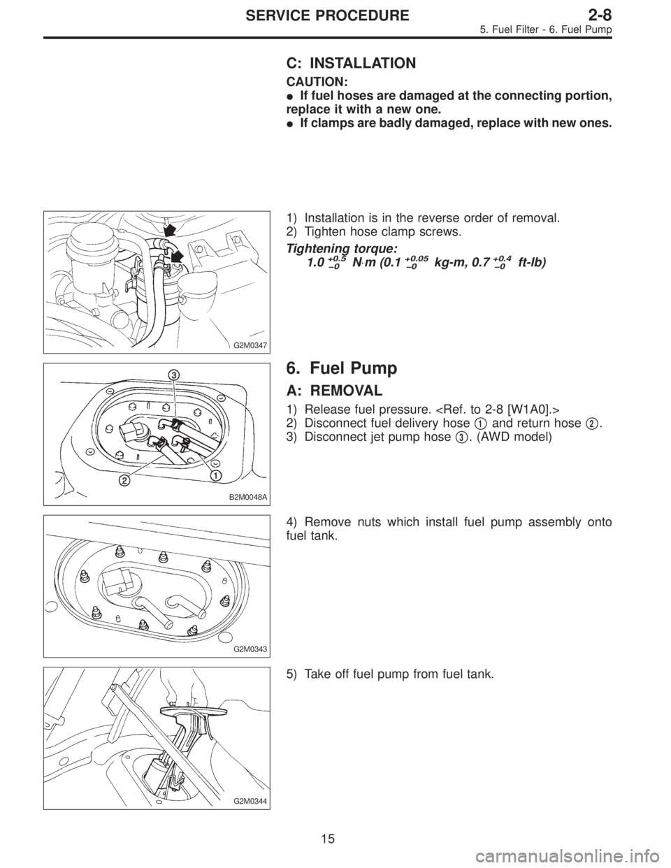
1) Installation is in the reverse order of removal.
2) Tighten hose clamp screws.
Tightening torque:
1.0
+0.5
0N⋅m (0.1+0.05
0kg-m, 0.7+0.4
0ft-lb)
B2M0048A
6. Fuel Pump
A: REMOVAL
1) Release fuel pressure.
2) Disconnect fuel delivery hose�
1and return hose�2.
3) Disconnect jet pump hose�
3. (AWD model)
G2M0343
4) Remove nuts which install fuel pump assembly onto
fuel tank.
G2M0344
5) Take off fuel pump from fuel tank.
15
2-8SERVICE PROCEDURE
5. Fuel Filter - 6. Fuel Pump
Page 203 of 2248
C: INSTALLATION
CAUTION:
�If fuel hoses are damaged at the connecting portion,
replace it with a new one.
�If clamps are badly damaged, replace with new ones.
G2M0347
1) Installation is in the reverse order of removal.
2) Tighten hose clamp screws.
Tightening torque:
1.0
+0.5
0N⋅m (0.1+0.05
0kg-m, 0.7+0.4
0ft-lb)
B2M0048A
6. Fuel Pump
A: REMOVAL
1) Release fuel pressure.
2) Disconnect fuel delivery hose�
1and return hose�2.
3) Disconnect jet pump hose�
3. (AWD model)
G2M0343
4) Remove nuts which install fuel pump assembly onto
fuel tank.
G2M0344
5) Take off fuel pump from fuel tank.
15
2-8SERVICE PROCEDURE
5. Fuel Filter - 6. Fuel Pump
Page 204 of 2248
G2M0366
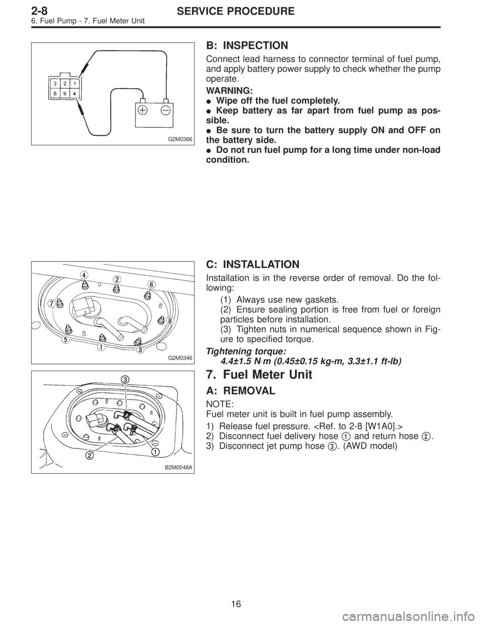
B: INSPECTION
Connect lead harness to connector terminal of fuel pump,
and apply battery power supply to check whether the pump
operate.
WARNING:
�Wipe off the fuel completely.
�Keep battery as far apart from fuel pump as pos-
sible.
�Be sure to turn the battery supply ON and OFF on
the battery side.
�Do not run fuel pump for a long time under non-load
condition.
G2M0346
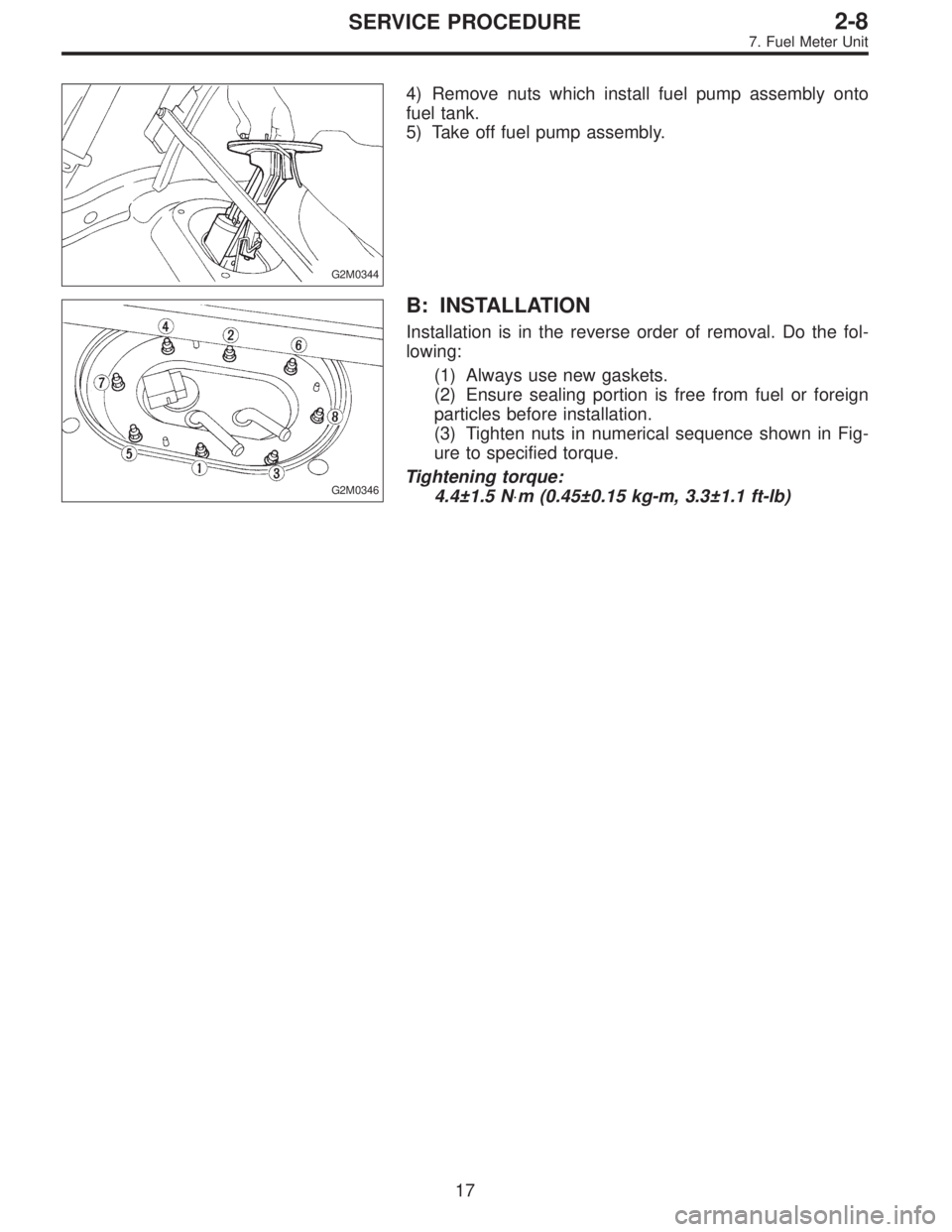
C: INSTALLATION
Installation is in the reverse order of removal. Do the fol-
lowing:
(1) Always use new gaskets.
(2) Ensure sealing portion is free from fuel or foreign
particles before installation.
(3) Tighten nuts in numerical sequence shown in Fig-
ure to specified torque.
Tightening torque:
4.4±1.5 N⋅m (0.45±0.15 kg-m, 3.3±1.1 ft-lb)
B2M0048A
7. Fuel Meter Unit
A: REMOVAL
NOTE:
Fuel meter unit is built in fuel pump assembly.
1) Release fuel pressure.
2) Disconnect fuel delivery hose�
1and return hose�2.
3) Disconnect jet pump hose�
3. (AWD model)
16
2-8SERVICE PROCEDURE
6. Fuel Pump - 7. Fuel Meter Unit
Page 205 of 2248
G2M0366
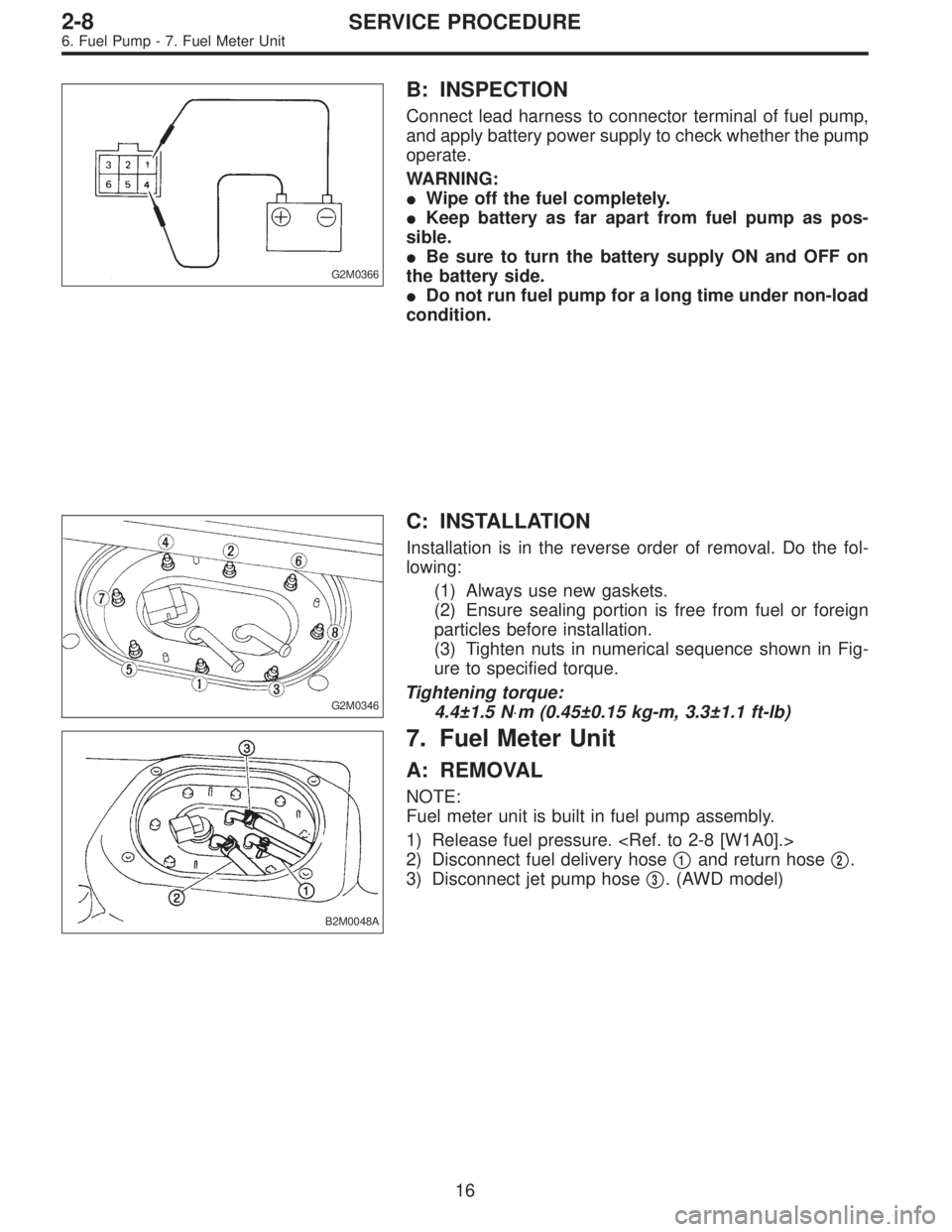
B: INSPECTION
Connect lead harness to connector terminal of fuel pump,
and apply battery power supply to check whether the pump
operate.
WARNING:
�Wipe off the fuel completely.
�Keep battery as far apart from fuel pump as pos-
sible.
�Be sure to turn the battery supply ON and OFF on
the battery side.
�Do not run fuel pump for a long time under non-load
condition.
G2M0346
C: INSTALLATION
Installation is in the reverse order of removal. Do the fol-
lowing:
(1) Always use new gaskets.
(2) Ensure sealing portion is free from fuel or foreign
particles before installation.
(3) Tighten nuts in numerical sequence shown in Fig-
ure to specified torque.
Tightening torque:
4.4±1.5 N⋅m (0.45±0.15 kg-m, 3.3±1.1 ft-lb)
B2M0048A
7. Fuel Meter Unit
A: REMOVAL
NOTE:
Fuel meter unit is built in fuel pump assembly.
1) Release fuel pressure.
2) Disconnect fuel delivery hose�
1and return hose�2.
3) Disconnect jet pump hose�
3. (AWD model)
16
2-8SERVICE PROCEDURE
6. Fuel Pump - 7. Fuel Meter Unit
Page 206 of 2248
G2M0344
4) Remove nuts which install fuel pump assembly onto
fuel tank.
5) Take off fuel pump assembly.
G2M0346
B: INSTALLATION
Installation is in the reverse order of removal. Do the fol-
lowing:
(1) Always use new gaskets.
(2) Ensure sealing portion is free from fuel or foreign
particles before installation.
(3) Tighten nuts in numerical sequence shown in Fig-
ure to specified torque.
Tightening torque:
4.4±1.5 N⋅m (0.45±0.15 kg-m, 3.3±1.1 ft-lb)
17
2-8SERVICE PROCEDURE
7. Fuel Meter Unit
Page 207 of 2248
8. Fuel Delivery, Return and
Evaporation Lines
A: REMOVAL
1) Release fuel pressure.
2) Remove inner trim, insulator and rear seat.
3) Remove fuel delivery pipes and hoses, fuel return pipes
and hoses, and evaporation pipes and hoses.
B2M0050A
�1Canister
�
2Fuel tank
�
3Fuel pump�
4Fuel cut valve (AWD)
�
5Fuel sub meter unit (AWD)
�
6Fuel filter
18
2-8SERVICE PROCEDURE
8. Fuel Delivery, Return and Evaporation Lines
Page 211 of 2248
G2M0864
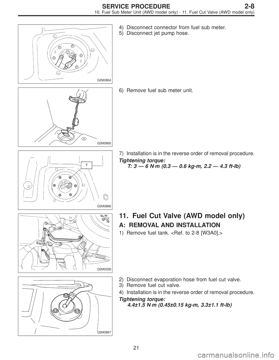
4) Disconnect connector from fuel sub meter.
5) Disconnect jet pump hose.
G2M0865
6) Remove fuel sub meter unit.
G2M0866
7) Installation is in the reverse order of removal procedure.
Tightening torque:
T: 3—6N⋅m (0.3—0.6 kg-m, 2.2—4.3 ft-lb)
G2M0356
11. Fuel Cut Valve (AWD model only)
A: REMOVAL AND INSTALLATION
1) Remove fuel tank.
G2M0867
2) Disconnect evaporation hose from fuel cut valve.
3) Remove fuel cut valve.
4) Installation is in the reverse order of removal procedure.
Tightening torque:
4.4±1.5 N⋅m (0.45±0.15 kg-m, 3.3±1.1 ft-lb)
21
2-8SERVICE PROCEDURE
10. Fuel Sub Meter Unit (AWD model only) - 11. Fuel Cut Valve (AWD model only)
Page 212 of 2248
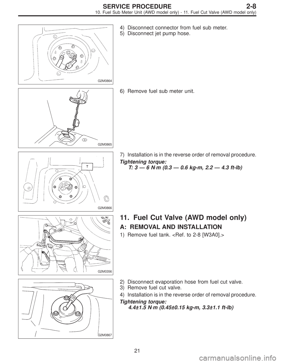
G2M0864
4) Disconnect connector from fuel sub meter.
5) Disconnect jet pump hose.
G2M0865
6) Remove fuel sub meter unit.
G2M0866
7) Installation is in the reverse order of removal procedure.
Tightening torque:
T: 3—6N⋅m (0.3—0.6 kg-m, 2.2—4.3 ft-lb)
G2M0356
11. Fuel Cut Valve (AWD model only)
A: REMOVAL AND INSTALLATION
1) Remove fuel tank.
G2M0867
2) Disconnect evaporation hose from fuel cut valve.
3) Remove fuel cut valve.
4) Installation is in the reverse order of removal procedure.
Tightening torque:
4.4±1.5 N⋅m (0.45±0.15 kg-m, 3.3±1.1 ft-lb)
21
2-8SERVICE PROCEDURE
10. Fuel Sub Meter Unit (AWD model only) - 11. Fuel Cut Valve (AWD model only)
![SUBARU LEGACY 1995 Service Repair Manual 8. Fuel Delivery, Return and
Evaporation Lines
A: REMOVAL
1) Release fuel pressure. <Ref. to 2-8 [W1A0].>
2) Remove inner trim, insulator and rear seat.
3) Remove fuel delivery pipes and hoses, fuel r](/manual-img/17/57432/w960_57432-206.png "SUBARU LEGACY 1995 Service Repair Manual 8. Fuel Delivery, Return and
Evaporation Lines
A: REMOVAL
1) Release fuel pressure. <Ref. to 2-8 [W1A0].>
2) Remove inner trim, insulator and rear seat.
3) Remove fuel delivery pipes and hoses, fuel r")