Page 825 of 2248
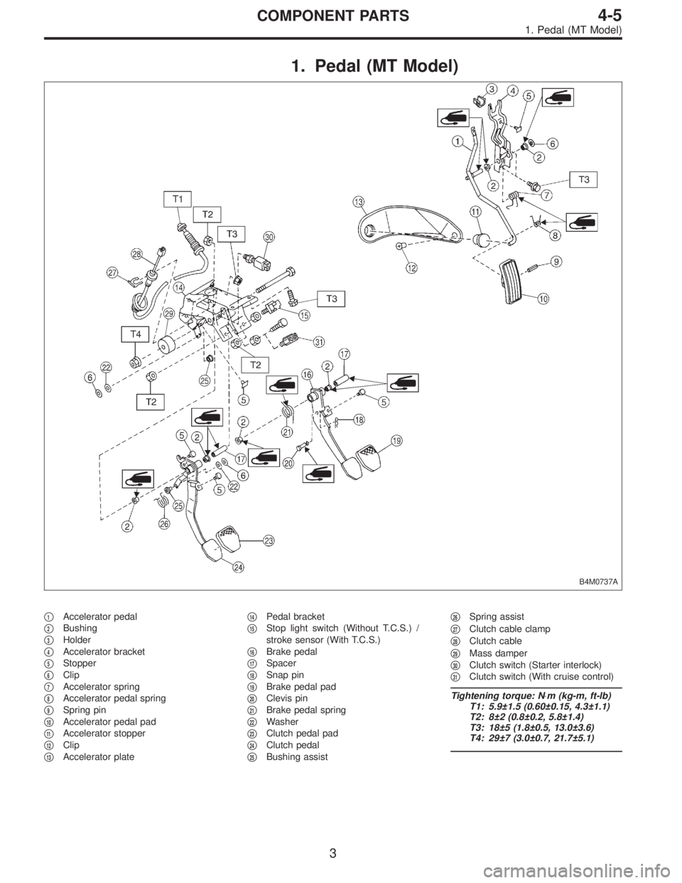
1. Pedal (MT Model)
B4M0737A
�1Accelerator pedal
�
2Bushing
�
3Holder
�
4Accelerator bracket
�
5Stopper
�
6Clip
�
7Accelerator spring
�
8Accelerator pedal spring
�
9Spring pin
�
10Accelerator pedal pad
�
11Accelerator stopper
�
12Clip
�
13Accelerator plate�
14Pedal bracket
�
15Stop light switch (Without T.C.S.) /
stroke sensor (With T.C.S.)
�
16Brake pedal
�
17Spacer
�
18Snap pin
�
19Brake pedal pad
�
20Clevis pin
�
21Brake pedal spring
�
22Washer
�
23Clutch pedal pad
�
24Clutch pedal
�
25Bushing assist�
26Spring assist
�
27Clutch cable clamp
�
28Clutch cable
�
29Mass damper
�
30Clutch switch (Starter interlock)
�
31Clutch switch (With cruise control)
Tightening torque: N⋅m (kg-m, ft-lb)
T1: 5.9±1.5 (0.60±0.15, 4.3±1.1)
T2: 8±2 (0.8±0.2, 5.8±1.4)
T3: 18±5 (1.8±0.5, 13.0±3.6)
T4: 29±7 (3.0±0.7, 21.7±5.1)
3
4-5COMPONENT PARTS
1. Pedal (MT Model)
Page 826 of 2248
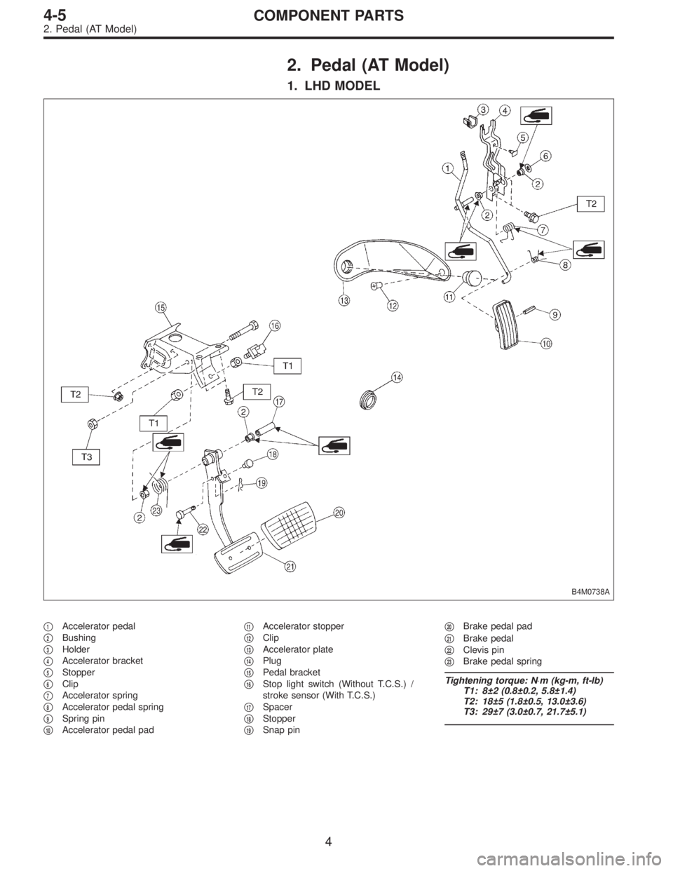
2. Pedal (AT Model)
1. LHD MODEL
B4M0738A
�1Accelerator pedal
�
2Bushing
�
3Holder
�
4Accelerator bracket
�
5Stopper
�
6Clip
�
7Accelerator spring
�
8Accelerator pedal spring
�
9Spring pin
�
10Accelerator pedal pad�
11Accelerator stopper
�
12Clip
�
13Accelerator plate
�
14Plug
�
15Pedal bracket
�
16Stop light switch (Without T.C.S.) /
stroke sensor (With T.C.S.)
�
17Spacer
�
18Stopper
�
19Snap pin�
20Brake pedal pad
�
21Brake pedal
�
22Clevis pin
�
23Brake pedal spring
Tightening torque: N⋅m (kg-m, ft-lb)
T1: 8±2 (0.8±0.2, 5.8±1.4)
T2: 18±5 (1.8±0.5, 13.0±3.6)
T3: 29±7 (3.0±0.7, 21.7±5.1)
4
4-5COMPONENT PARTS
2. Pedal (AT Model)
Page 827 of 2248
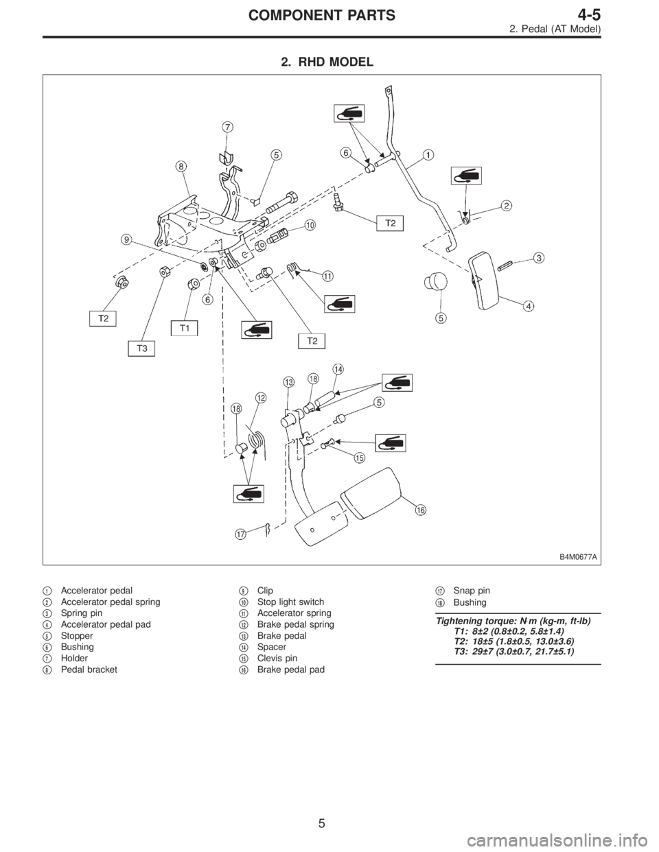
2. RHD MODEL
B4M0677A
�1Accelerator pedal
�
2Accelerator pedal spring
�
3Spring pin
�
4Accelerator pedal pad
�
5Stopper
�
6Bushing
�
7Holder
�
8Pedal bracket�
9Clip
�
10Stop light switch
�
11Accelerator spring
�
12Brake pedal spring
�
13Brake pedal
�
14Spacer
�
15Clevis pin
�
16Brake pedal pad�
17Snap pin
�
18Bushing
Tightening torque: N⋅m (kg-m, ft-lb)
T1: 8±2 (0.8±0.2, 5.8±1.4)
T2: 18±5 (1.8±0.5, 13.0±3.6)
T3: 29±7 (3.0±0.7, 21.7±5.1)
5
4-5COMPONENT PARTS
2. Pedal (AT Model)
Page 828 of 2248
 Check position of pedal pad.
�
1Stop light switch
�
2Mat
�
3Toe board
�
4Brake booster operating rod
Pedal height: L
148 mm (5.83 in)
If it is not")
B4M0366A
1. Pedal
A: ON-CAR SERVICE
1. BRAKE PEDAL
1) Check position of pedal pad.
�
1Stop light switch
�
2Mat
�
3Toe board
�
4Brake booster operating rod
Pedal height: L
148 mm (5.83 in)
If it is not in specified value, adjust it by adjusting brake
booster operating rod length.
2) Check free play by operating pedal by hand.
If it is not in specified value, adjust it by adjusting position
of stop light switch.
CAUTION:
Be careful not to rotate stop light switch.
Brake pedal free play: A
1 — 3 mm (0.04 — 0.12 in)
[Depress brake pedal pad with a force of less than
10 N (1 kg, 2 lb).]
Stop light switch lock nut tightening torque:
8±2 N⋅m (0.8±0.2 kg-m, 5.8±1.4 ft-lb)
3) Apply grease to operating rod connecting pin to prevent
it from wearing.
G4M0318
2. CLUTCH PEDAL
1) Check clutch pedal free play by operating pedal by
hand.
Free play: L (At clutch pedal pad)
10 — 20 mm (0.39 — 0.79 in)
B4M0367A
Pedal height: Y
158 mm (6.22 in)
Pedal stroke: A
140 — 145 mm (5.51 — 5.71 in)
�
1Toe board
�
2Mat
6
4-5SERVICE PROCEDURE
1. Pedal
Page 829 of 2248
G4M0319
2) If it is not in specified value, adjust it by turning adjust-
ing nut on engine side end of clutch cable.
Free play: L
3—4 mm (0.12—0.16 in)
Full stroke: A
25.5—27 mm (1.004—1.063 in)
3) Apply grease to connecting portion of clutch pedal and
clutch cable.
�
1Lock nut
�
2Adjusting nut
�
3Release fork
Lock nut tightening torque:
5.9±1.5 N⋅m (0.60±0.15 kg-m, 4.3±1.1 ft-lb)
G4M0320
3. ACCELERATOR PEDAL
Check pedal stroke and free play by operating accelerator
pedal by hand.
If it is not within specified value, adjust it by turning nut
connecting accelerator cable to throttle body.
Free play at pedal pad: L
1—4 mm (0.04—0.16 in)
Stroke at pedal pad: A
50—55 mm (1.97—2.17 in)
�
1Accelerator pedal
�
2Toe board
�
3Accelerator cable
Accelerator cable lock nut tightening torque:
14±4 N⋅m (1.4±0.4 kg-m, 10.1±2.9 ft-lb)
7
4-5SERVICE PROCEDURE
1. Pedal
Page 835 of 2248
G4M0329
D: ASSEMBLY
1. BRAKE AND CLUTCH PEDAL
1) Attach stop light switch, etc. to pedal bracket tempo-
rarily.
2) Clean inside of bores of clutch pedal and brake pedal,
apply grease, and set bushings into bores.
3) Align bores of pedal bracket, clutch pedal and brake
pedal, attach brake pedal return spring and clutch pedal
effort reducing spring (vehicle with hill holder), and then
install pedal bolt.
Tightening torque:
T2: 29±7 N⋅m (3.0±0.7 kg-m, 21.7±5.1 ft-lb)
NOTE:
Clean up inside of bushings and apply grease before
installing spacer.
4) Set brake pedal position by adjusting position of stop
light switch.
Pedal position: L
125.9 mm (4.96 in)
Tightening torque:
T1: 8±2 N⋅m (0.8±0.2 kg-m, 5.8±1.4 ft-lb)
2. ACCELERATOR PEDAL
Clean and apply grease to spacer and inside bore of accel-
erator pedal. Install accelerator pedal onto pedal bracket.
13
4-5SERVICE PROCEDURE
1. Pedal
Page 843 of 2248
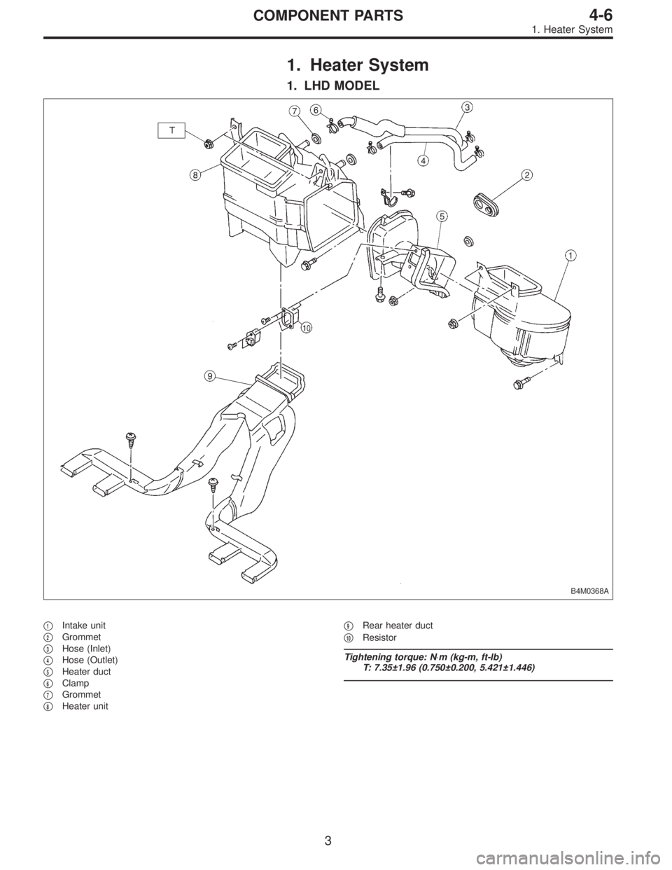
1. Heater System
1. LHD MODEL
B4M0368A
�1Intake unit
�
2Grommet
�
3Hose (Inlet)
�
4Hose (Outlet)
�
5Heater duct
�
6Clamp
�
7Grommet
�
8Heater unit�
9Rear heater duct
�
10Resistor
Tightening torque: N⋅m (kg-m, ft-lb)
T: 7.35±1.96 (0.750±0.200, 5.421±1.446)
3
4-6COMPONENT PARTS
1. Heater System
Page 844 of 2248
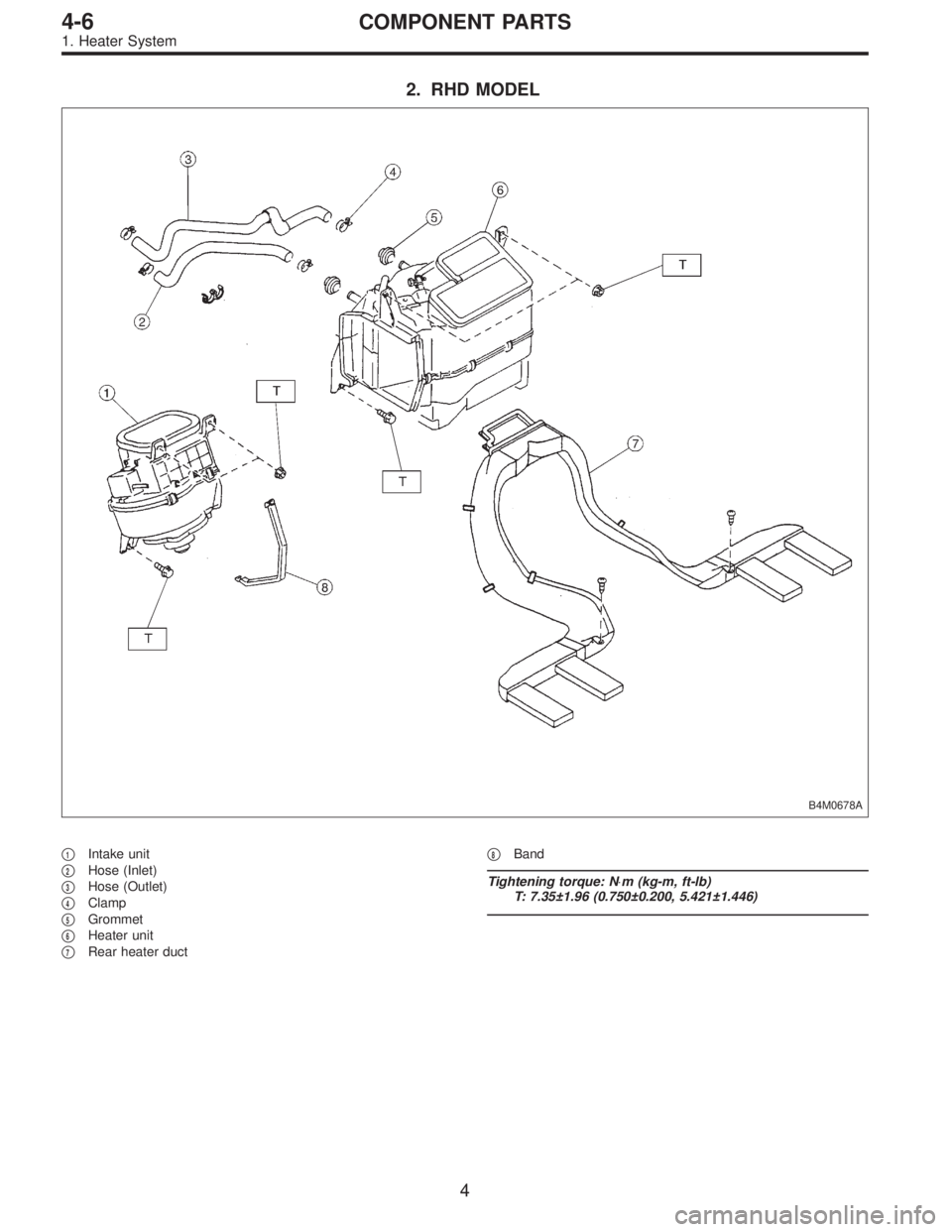
2. RHD MODEL
B4M0678A
�1Intake unit
�
2Hose (Inlet)
�
3Hose (Outlet)
�
4Clamp
�
5Grommet
�
6Heater unit
�
7Rear heater duct�
8Band
Tightening torque: N⋅m (kg-m, ft-lb)
T: 7.35±1.96 (0.750±0.200, 5.421±1.446)
4
4-6COMPONENT PARTS
1. Heater System
 If it is not in specified value, adjust it by turning adjust-
ing nut on engine side end of clutch cable.
Free play: L
3—4 mm (0.12—0.16 in)
Full stroke: A
25.5—27 mm (1.004—1.063 i")
 Attach stop light switch, etc. to pedal bracket tempo-
rarily.
2) Clean inside of bores of clutch pedal and brake pedal,
apply grease, and set bushings")