Page 1241 of 2248

2. READ DATA FUNCTION KEY LIST FOR ENGINE
Function mode Contents Abbreviation Unit of measure
F00 ROM ID number YEAR—
F01 Battery voltage VB V
F02 Vehicle speed signal VSP m/h
F03 Vehicle speed signal VSP km/h
F04 Engine speed signal EREV rpm
F05 Engine coolant temperature signal TW°F
F06 Engine coolant temperature signal TW°C
F07 Ignition signal ADVS deg
F08 Mass air flow signal QA V
F09 Load data DATA—
F10 Throttle position signal THV V
F11 Injector pulse width TIM mS
F12 Idle air control signal ISC %
F13 Front oxygen sensor output signal FO2 V
F14 Front oxygen sensor maximum output signal FO2max V
F15 Front oxygen sensor minimum output signal FO2min V
F16 Rear oxygen sensor output signal RO2 V
F17 Rear oxygen sensor maximum output signal RO2max V
F18 Rear oxygen sensor minimum output signal RO2min V
F19 Short term fuel trim ALPHA %
F20 Knock sensor signal RTRD deg
F21 A/F correction (short term trim) by rear oxygen sensor PHOS %
F23 Atmospheric absolute pressure signal (AT vehicles) BARO. P V
F24 Intake manifold absolute pressure signal (AT vehicles) MANI. P V
F25 Long term fuel trim KBLRC %
F28 Long term whole fuel trim K0 %
F29 Front oxygen sensor heater current FO2H A
F30 Rear oxygen sensor heater current RO2H A
F33Maximum value of cylinder #1 misfire times during 200
rotationsMF1 %
F34Maximum value of cylinder #2 misfire times during 200
rotationsMF2 %
F35Maximum value of cylinder #3 misfire times during 200
rotationsMF3 %
F36Maximum value of cylinder #4 misfire times during 200
rotationsMF4 %
F37 Maximum EGR system pressure value (AT vehicles) EGRmax mmHg
F38 Minimum EGR system pressure value (AT vehicles) EGRmin mmHg
F45 Load data LOAD %
F46 Throttle position signal THV %
F47 Mass air flow signal QA g/s
F48 Atmospheric absolute pressure signal BARO. P kPa
F49 Intake manifold absolute pressure signal MANI. P kPa
35
2-7ON-BOARD DIAGNOSTICS II SYSTEM
3. Diagnosis System
Page 1245 of 2248
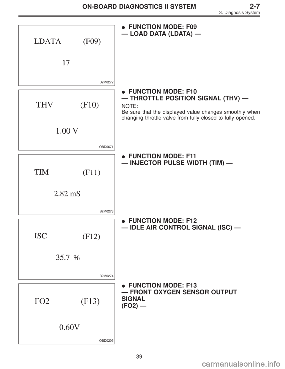
B2M0272
�FUNCTION MODE: F09
—LOAD DATA (LDATA)—
OBD0671
�FUNCTION MODE: F10
—THROTTLE POSITION SIGNAL (THV)—
NOTE:
Be sure that the displayed value changes smoothly when
changing throttle valve from fully closed to fully opened.
B2M0273
�FUNCTION MODE: F11
—INJECTOR PULSE WIDTH (TIM)—
B2M0274
�FUNCTION MODE: F12
—IDLE AIR CONTROL SIGNAL (ISC)—
OBD0205
�FUNCTION MODE: F13
—FRONT OXYGEN SENSOR OUTPUT
SIGNAL
(FO2)—
39
2-7ON-BOARD DIAGNOSTICS II SYSTEM
3. Diagnosis System
Page 1609 of 2248
G2M0931
(4) Push the TCS OFF switch to ON. (with TCS mod-
els)
(5) Start the engine.
(6) Shift on the gear position, and keep the vehicle
speed at constant.
(7) Measure signal voltage.
Specified voltage: 2 V, or more
NOTE:
If vehicle speed increases, the width of amplitude (W)
decreases.
NOTE:
The speed difference between front and rear wheels may
light either the ABS or the ABS/TCS warning light, but this
indicates no malfunctions. When AT control diagnosis is
finished, perform the ABS or the ABS/TCS memory clear-
ance procedure of self-diagnosis system.
54
3-2AUTOMATIC TRANSMISSION AND DIFFERENTIAL
7. Diagnostic Chart with Trouble Code
Page 1877 of 2248
 Start the engine.
4) Shift on the gear position, and keep the vehicle speed
at constant.
5) Measure signal voltage.
Specified voltage (V): 2 V, or more
NOTE:
�If the vehicle speed i")
G2M0931
B6M0287
3) Start the engine.
4) Shift on the gear position, and keep the vehicle speed
at constant.
5) Measure signal voltage.
Specified voltage (V): 2 V, or more
NOTE:
�If the vehicle speed increases, the width of amplitude
(W) decreases.
�If oscilloscope is not available, check input signal
(vehicle speed signal) by using a select monitor. (Refer to
the procedure as described below.)
�Using the select monitor:
(1) Set the vehicle on free roller, or lift-up the vehicle and
support with safety stands.
(2) Turn ignition switch to OFF and set select monitor.
(3) Turn ignition switch to ON.
(4) Turn cruise control main switch to ON.
(5) Set select monitor in“F01”or“F02”mode.
(6) Drive the vehicle at speed greater than 40 km/h (25
MPH).
(7) Check that vehicle speed indication on select moni-
tor and speedometer are equal.
NOTE:
�When there is a disconnection or short circuit in the har-
ness between the meter and the cruise control module, the
indicated value will be 0 to 1.0 km/h (0 to 0.6 MPH).
�In“F01”mode, vehicle speed is indicated in mile per
hour (MPH).
In“F02”mode, vehicle speed is indicated in kilometer per
hour (km/h).
B3M0250
3. PERFORM A CIRCUIT TEST BETWEEN
COMBINATION METER AND CRUISE CONTROL
MODULE.
1) Turn ignition switch to OFF.
2) Remove combination meter.
B6M0194B
3) Disconnect connector from cruise control module.
4) Measure resistance of harness connector between
combination meter and cruise control module.
Connector & terminal / Specified resistance:
(i10) No. 10—(B94) No. 19 / 10Ω, max.
24
6-2BODY ELECTRICAL SYSTEM
8. Diagnostics Chart with Trouble Code
Page:
< prev 1-8 9-16 17-24
 Push the TCS OFF switch to ON. (with TCS mod-
els)
(5) Start the engine.
(6) Shift on the gear position, and keep the vehicle
speed at constant.
(7) Measure signal voltage.
Specified volta")