Page 717 of 2248
1. Brakes
A: SPECIFICATIONS
1. MODELS WITH ABS AND ABS/TCS
Model Sedan Wagon
Engine (cc) 2200 2200
Driving system FWD AWD FWD AWD
L+ L+ LS, LSi L+ L, L+ LS, LSi
Front
brakeType Disc (Floating type, ventilated)
Effective disc diameter
mm (in)210 (8.27)
Disc thickness x Outer
diameter
mm (in)24 x 260 (0.94 x 10.24)
Effective cylinder
diameter
mm (in)57.2 (2.252)
Pad dimensions
(length x width x
thickness)
mm (in)112.4 x 44.3 x 11.0 (4.43 x 1.744 x 0.433)
Clearance adjustment Automatic adjustment
Rear
brakeType Disc (Floating type)
Effective disc diameter
mm (in)230 (9.06)
Disc thickness x Outer
diameter
mm (in)10 x 266 (0.39 x 10.47)
Effective cylinder
diameter
mm (in)34.9 (1.374) 38.1 (1.500)
Pad dimensions
(length x width x
thickness)
mm (in)92.4 x 33.7 x 10.0 (3.638 x 1.327 x 0.394)
Clearance adjustment Automatic adjustment
2
4-4SPECIFICATIONS AND SERVICE DATA
1. Brakes
Page 718 of 2248
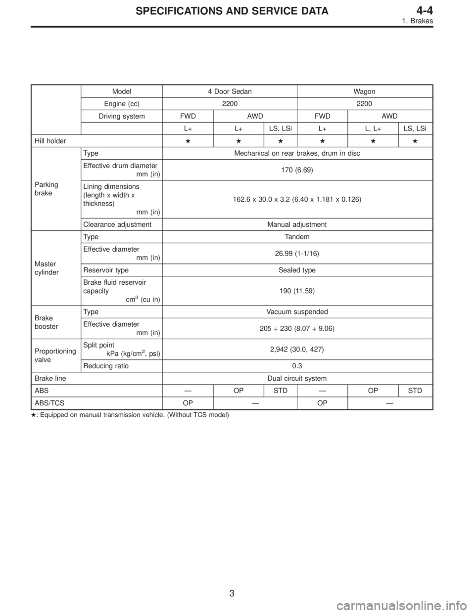
Model 4 Door Sedan Wagon
Engine (cc) 2200 2200
Driving system FWD AWD FWD AWD
L+ L+ LS, LSi L+ L, L+ LS, LSi
Hill holder� ��� ��
Parking
brakeType Mechanical on rear brakes, drum in disc
Effective drum diameter
mm (in)170 (6.69)
Lining dimensions
(length x width x
thickness)
mm (in)162.6 x 30.0 x 3.2 (6.40 x 1.181 x 0.126)
Clearance adjustment Manual adjustment
Master
cylinderType Tandem
Effective diameter
mm (in)26.99 (1-1/16)
Reservoir type Sealed type
Brake fluid reservoir
capacity
cm
3(cu in)190 (11.59)
Brake
boosterType Vacuum suspended
Effective diameter
mm (in)205 + 230 (8.07 + 9.06)
Proportioning
valveSplit point
kPa (kg/cm
2, psi)2,942 (30.0, 427)
Reducing ratio 0.3
Brake line Dual circuit system
ABS—OP STD—OP STD
ABS/TCS OP—OP—
�: Equipped on manual transmission vehicle. (Without TCS model)
3
4-4SPECIFICATIONS AND SERVICE DATA
1. Brakes
Page 719 of 2248
2. MODELS WITHOUT ABS AND ABS/TCS
Model Sedan Wagon
Engine (cc) 2200 2200
Driving system FWD AWD FWD AWD
BASE L+ L+ BASE L+ BRIGHTON L.L+
Front
brakeType Disc (Floating type, ventilated)
Effective disc diameter
mm (in)210 (8.27)
Disc thickness x Outer
diameter
mm (in)24 x 260 (0.94 x 10.24)
Effective cylinder
diameter
mm (in)57.2 (2.252)
Pad dimensions
(length x width x
thickness)
mm (in)112.4 x 44.3 x 11.0 (4.43 x 1.744 x 0.433)
Clearance adjustment Automatic adjustment
Rear
brakeType Drum (Leading-Trailing type)
Effective drum diameter
mm (in)228.6 (9)
Effective cylinder
diameter
mm (in)17.4 (0.685) 19.0 (0.748)
Lining dimensions
(length x width x
thickness)
mm (in)218.8 x 35.0 x 4.1 (8.61 x 1.378 x 0.161)
Clearance adjustment Automatic adjustment
4
4-4SPECIFICATIONS AND SERVICE DATA
1. Brakes
Page 720 of 2248
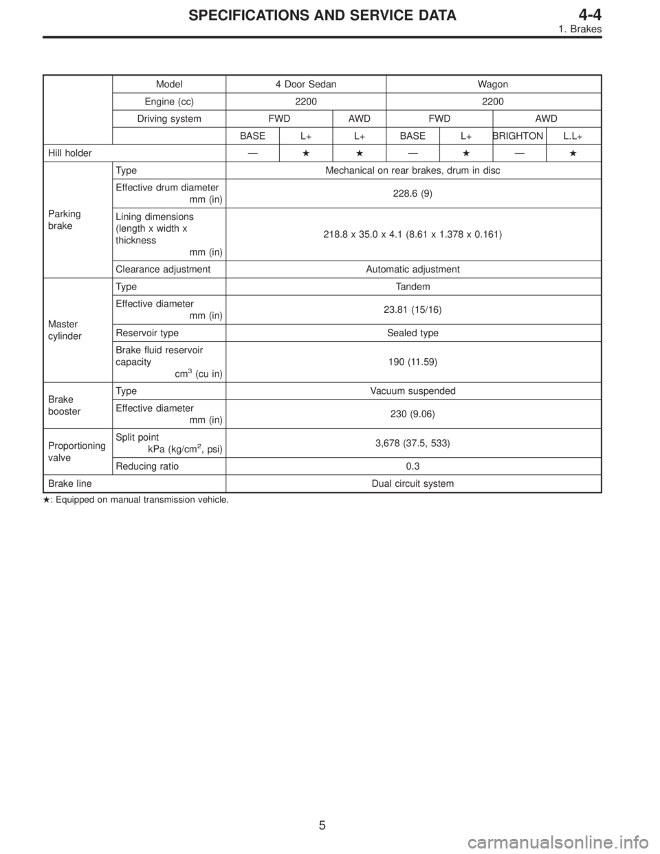
Model 4 Door Sedan Wagon
Engine (cc) 2200 2200
Driving system FWD AWD FWD AWD
BASE L+ L+ BASE L+ BRIGHTON L.L+
Hill holder—��—�—�
Parking
brakeType Mechanical on rear brakes, drum in disc
Effective drum diameter
mm (in)228.6 (9)
Lining dimensions
(length x width x
thickness
mm (in)218.8 x 35.0 x 4.1 (8.61 x 1.378 x 0.161)
Clearance adjustment Automatic adjustment
Master
cylinderType Tandem
Effective diameter
mm (in)23.81 (15/16)
Reservoir type Sealed type
Brake fluid reservoir
capacity
cm
3(cu in)190 (11.59)
Brake
boosterType Vacuum suspended
Effective diameter
mm (in)230 (9.06)
Proportioning
valveSplit point
kPa (kg/cm
2, psi)3,678 (37.5, 533)
Reducing ratio 0.3
Brake line Dual circuit system
�: Equipped on manual transmission vehicle.
5
4-4SPECIFICATIONS AND SERVICE DATA
1. Brakes
Page 842 of 2248
 or more ...
When 300 m
3(10,593 cu ft)/h�Mode
selector
switch:")
1. Heater System
A: SPECIFICATIONS
ItemSpecifications
Condition
LHD model RHD model
Heating capacity4.652 kW (4,000 kcal/h, 15,872 BTU/h) or more ...
When 300 m
3(10,593 cu ft)/h�Mode
selector
switch: HEAT
�Te m p .
control
lever: FULL HOT
�Temperature
difference
between
hot water
and inlet air:65°C
(149°F)
�Hot water
flow rate: 360�(95.1
US gal, 79.2
Imp gal)/h
Air flow rate 300 m
3(10,593 cu ft)/h 280 m3(9,887 cu ft)/hHeat mode (FRESH), FULL
HOT at 12.5 V
Max air flow rate 510 m
3(18,008 cu ft)/h 480 m3(16,949 cu ft)/h�Temperature
control
lever: FULL COLD
�Blower fan
speed: 4th position
�RECIRC
switch
position: RECIRC
Heater core size
(height x length x width x
thickness)193.5 x 152.0 x 25.0 x 0.9 mm
(7.62 x 5.98 x 0.984 x 0.035 in)159.5 x 180 x 32.0 x 1.0 mm
(6.28 x 7.09 x 1.26 x 0.039 in)—
Blower
motorType Magnet motor 230 W or less Magnet motor 220 W or less at 12 V
Fan type and size
(diameter x width)Sirocco fan type
150 x 75 mm (5.91 x 2.95 in)Sirocco fan type
140 x 65 mm (5.51 x 2.56 in)—
2
4-6SPECIFICATIONS AND SERVICE DATA
1. Heater System
Page 862 of 2248
4.885 kW
(4,200 kcal/h, 16,666 BTU/h)
RefrigerantHFC-134a (CH
2FCF3)")
1. Air Conditioning System
A: SPECIFICATIONS
Item Specifications
Type of air conditionerReheat air-mix type
Cooling capacity (IMACA)4.885 kW
(4,200 kcal/h, 16,666 BTU/h)
RefrigerantHFC-134a (CH
2FCF3)
[0.6 — 0.7 kg
(1.3 — 1.5 lb)]
CompressorType Swash plate type (DKS-15CH)
Discharge 147 cm
3(8.97 cu in)/rev
Max. permissible speed 7,000 rpm
Magnet clutchTy p eDry, single-disc type
Power consumption 44 W
Type of belt V-Ribbed 4 PK
Pulley dia. (effective dia.) 115 mm (4.53 in)
Pulley ratio1.16
CondenserType Corrugated fin (Multi-flow)
Core face area 0.215 m
2(2.31 sq ft)
Core thickness 19 mm (0.75 in)
Radiation area 4.7 m
2(51 sq ft)
Receiver drier Effective inner capacity 290 cm3(17.70 cu in)
Expansion valve TypeExternal equalizing
EvaporatorTy p eA�-laminate
Dimensions (W x H x T)74 x 224 x 235 mm
(2.91 x 8.82 x 9.25 in)
Blower fanFan typeSirocco fan
Outer diameter x width 150 x 75 mm (5.91 x 2.95 in)
Power consumption 230 W at 12 V
Condenser fan
(Sub fan)Motor typeMagnet
Power consumption 120 W at 12 V
Fan outer diameter 320 mm (12.60 in)
Radiator fan
(Main fan)Motor typeMagnet
Power consumption 120 W at 12 V
Fan outer diameter 320 mm (12.60 in)
Idling speed with
F.I.C.D. in operationMPFI model 850±50 rpm (700±50 rpm “D” range in AT model)
Dual switch
(Pressure switch)
High-pressure line
B4M0083A
Compressor relief valve
blow-out pressure
B4M0084A
Thermo control
amplifier working
temperature
(Evaporator outlet air)
G4M0938
2
4-7SPECIFICATIONS
1. Air Conditioning System
Page 1133 of 2248
 When tester indicates 12 volts when its probe reaches
point“A”, a broken circuit occurs between point“A”and the
negative terminal. Slowly move tester probe toward the
negative termi")
G6M0137
4) When tester indicates 12 volts when its probe reaches
point“A”, a broken circuit occurs between point“A”and the
negative terminal. Slowly move tester probe toward the
negative terminal while contacting it on heat wire to locate
point where tester indication changes abruptly (0 volts).
This is the point where a broken circuit occurs.
When tester indicates 0 volts when its probe reaches point
“A”, a broken circuit occurs between point“A”and the posi-
tive terminal. Locate a point where tester indication
changes abruptly (12 volts) while slowly moving tester
probe toward the positive terminal.
G6M0138
C: REPAIR
1) Clean broken wire and its surrounding area.
2) Cut off slit on (used) thin film by 0.5 mm (0.020 in) width
and 10 mm (0.39 in) length.
3) Place the slit on glass along the broken wire, and
deposit conductive silver composition (DUPONT No. 4817)
on the broken portion.
4) Dry out the deposited portion.
5) Inspect the repaired wire for continuity.
B6M0120
13. Combination Meter
A: REMOVAL AND INSTALLATION
1. COMBINATION METER
1) Move steering wheel fully down.
2) Remove screws which secure meter visor.
3) Remove visor from instrument panel.
4) Disconnect connectors from meter visor.
B6M0121
5) Remove screws which secure combination meter, and
pull combination meter out.
6) Disconnect connectors from back of combination meter.
CAUTION:
When installing combination meter, be sure to connect
connectors to backside of combination meter.
33
6-2SERVICE PROCEDURE
12. Rear Window Defogger - 13. Combination Meter
Page 1134 of 2248
 When tester indicates 12 volts when its probe reaches
point“A”, a broken circuit occurs between point“A”and the
negative terminal. Slowly move tester probe toward the
negative termi")
G6M0137
4) When tester indicates 12 volts when its probe reaches
point“A”, a broken circuit occurs between point“A”and the
negative terminal. Slowly move tester probe toward the
negative terminal while contacting it on heat wire to locate
point where tester indication changes abruptly (0 volts).
This is the point where a broken circuit occurs.
When tester indicates 0 volts when its probe reaches point
“A”, a broken circuit occurs between point“A”and the posi-
tive terminal. Locate a point where tester indication
changes abruptly (12 volts) while slowly moving tester
probe toward the positive terminal.
G6M0138
C: REPAIR
1) Clean broken wire and its surrounding area.
2) Cut off slit on (used) thin film by 0.5 mm (0.020 in) width
and 10 mm (0.39 in) length.
3) Place the slit on glass along the broken wire, and
deposit conductive silver composition (DUPONT No. 4817)
on the broken portion.
4) Dry out the deposited portion.
5) Inspect the repaired wire for continuity.
B6M0120
13. Combination Meter
A: REMOVAL AND INSTALLATION
1. COMBINATION METER
1) Move steering wheel fully down.
2) Remove screws which secure meter visor.
3) Remove visor from instrument panel.
4) Disconnect connectors from meter visor.
B6M0121
5) Remove screws which secure combination meter, and
pull combination meter out.
6) Disconnect connectors from back of combination meter.
CAUTION:
When installing combination meter, be sure to connect
connectors to backside of combination meter.
33
6-2SERVICE PROCEDURE
12. Rear Window Defogger - 13. Combination Meter
 2200 2200
Driving system FWD AWD FWD AWD
L+ L+ LS, LSi L+ L, L+ LS, LSi
Front
brakeType Disc (Floating type, ve")
 2200 2200
Driving system FWD AWD FWD AWD
BASE L+ L+ BASE L+ BRIGHTON L.L+
Front
brakeType Disc (Floating type, ventilated)
Effective dis")