Page 891 of 2248
11. Compressor
Compressor is a swash plate type. When trouble occurs,
replace compressor as a single unit.
B4M0090
A: COMPRESSOR CLUTCH INSPECTION
Compressor clutch trouble is often caused by clutch slip-
page and noise. Check and take corrective measures, as
required.
1) Remove belt cover.
2) Check that clearance between drive plate and pulley
over the entire perimeter is within specifications.
Clearance:
0.3 — 0.6 mm (0.012 — 0.024 in)
B4M0091
3) Check that voltage applied to magnetic coil is at least
10.5 volts.
4) When noise is noted, check that it originates in either
compressor or pulley bearing.
31
4-7SERVICE PROCEDURE
11. Compressor
Page 1067 of 2248
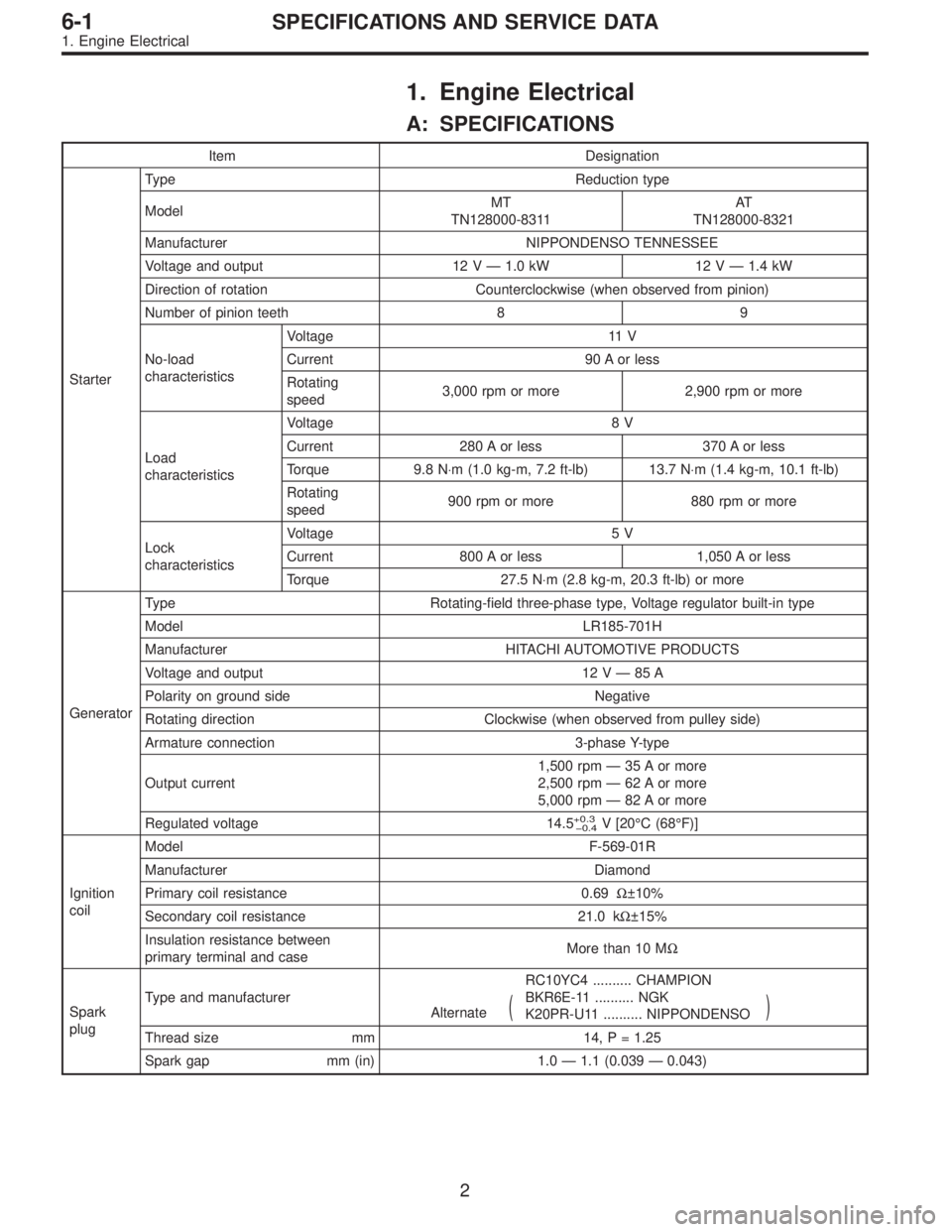
1. Engine Electrical
A: SPECIFICATIONS
Item Designation
StarterType Reduction type
ModelMT
TN128000-8311AT
TN128000-8321
Manufacturer NIPPONDENSO TENNESSEE
Voltage and output 12 V — 1.0 kW 12 V — 1.4 kW
Direction of rotation Counterclockwise (when observed from pinion)
Number of pinion teeth 8 9
No-load
characteristicsVoltage 11 V
Current 90 A or less
Rotating
speed3,000 rpm or more 2,900 rpm or more
Load
characteristicsVoltage 8 V
Current 280 A or less 370 A or less
Torque 9.8 N⋅m (1.0 kg-m, 7.2 ft-lb) 13.7 N⋅m (1.4 kg-m, 10.1 ft-lb)
Rotating
speed900 rpm or more 880 rpm or more
Lock
characteristicsVoltage 5 V
Current 800 A or less 1,050 A or less
Torque 27.5 N⋅m (2.8 kg-m, 20.3 ft-lb) or more
GeneratorType Rotating-field three-phase type, Voltage regulator built-in type
Model LR185-701H
Manufacturer HITACHI AUTOMOTIVE PRODUCTS
Voltage and output 12 V — 85 A
Polarity on ground side Negative
Rotating direction Clockwise (when observed from pulley side)
Armature connection 3-phase Y-type
Output current1,500 rpm — 35 A or more
2,500 rpm — 62 A or more
5,000 rpm — 82 A or more
Regulated voltage 14.5
+0.3
�0.4V [20°C (68°F)]
Ignition
coilModel F-569-01R
Manufacturer Diamond
Primary coil resistance 0.69Ω±10%
Secondary coil resistance 21.0 kΩ±15%
Insulation resistance between
primary terminal and caseMore than 10 MΩ
Spark
plugType and manufacturerRC10YC4 .......... CHAMPION
Alternate
(BKR6E-11 .......... NGK
K20PR-U11 .......... NIPPONDENSO)
Thread size mm 14, P = 1.25
Spark gap mm (in) 1.0 — 1.1 (0.039 — 0.043)
2
6-1SPECIFICATIONS AND SERVICE DATA
1. Engine Electrical
Page 1088 of 2248
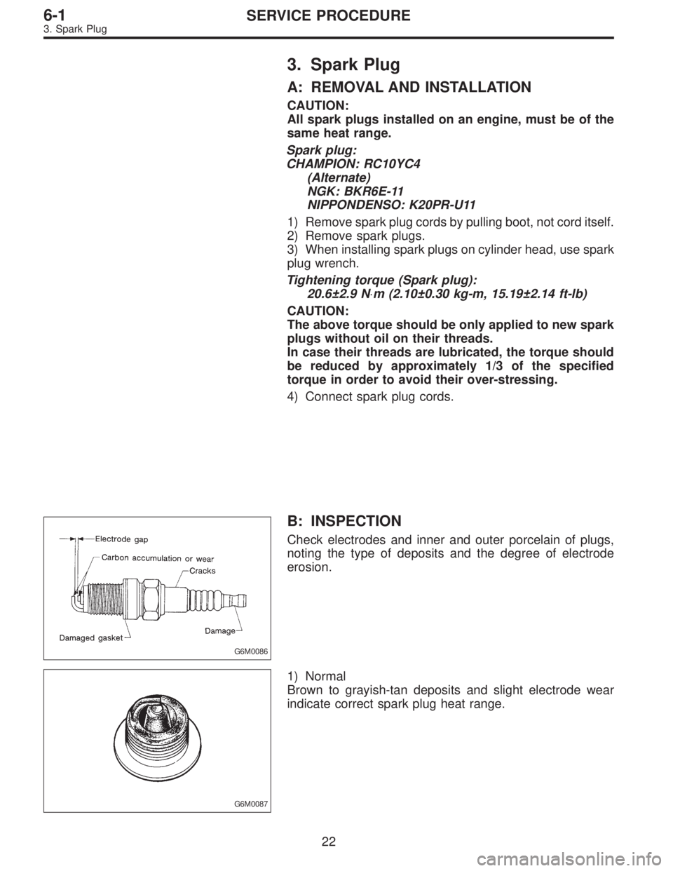
3. Spark Plug
A: REMOVAL AND INSTALLATION
CAUTION:
All spark plugs installed on an engine, must be of the
same heat range.
Spark plug:
CHAMPION: RC10YC4
(Alternate)
NGK: BKR6E-11
NIPPONDENSO: K20PR-U11
1) Remove spark plug cords by pulling boot, not cord itself.
2) Remove spark plugs.
3) When installing spark plugs on cylinder head, use spark
plug wrench.
Tightening torque (Spark plug):
20.6±2.9 N⋅m (2.10±0.30 kg-m, 15.19±2.14 ft-lb)
CAUTION:
The above torque should be only applied to new spark
plugs without oil on their threads.
In case their threads are lubricated, the torque should
be reduced by approximately 1/3 of the specified
torque in order to avoid their over-stressing.
4) Connect spark plug cords.
G6M0086
B: INSPECTION
Check electrodes and inner and outer porcelain of plugs,
noting the type of deposits and the degree of electrode
erosion.
G6M0087
1) Normal
Brown to grayish-tan deposits and slight electrode wear
indicate correct spark plug heat range.
22
6-1SERVICE PROCEDURE
3. Spark Plug
Page 1089 of 2248
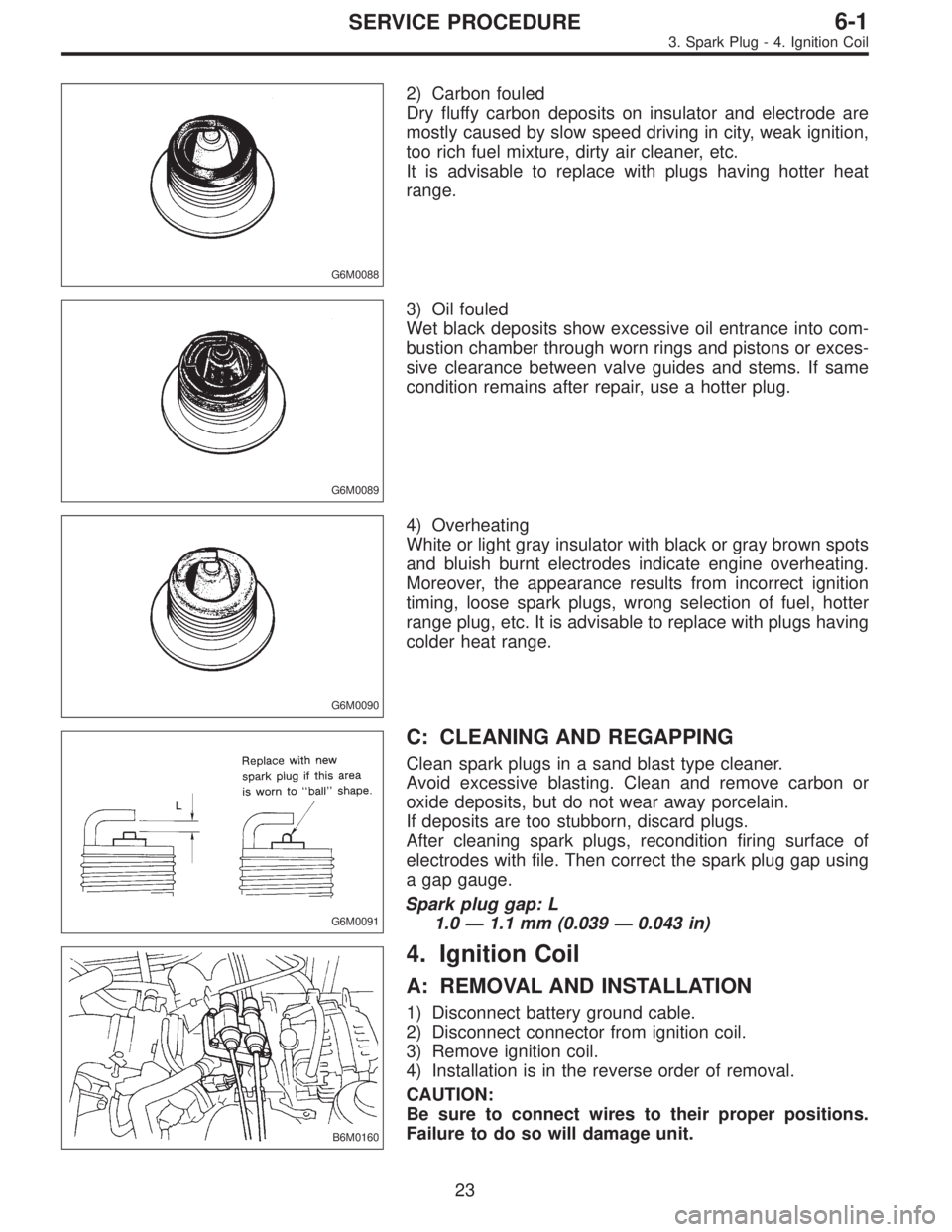
G6M0088
2) Carbon fouled
Dry fluffy carbon deposits on insulator and electrode are
mostly caused by slow speed driving in city, weak ignition,
too rich fuel mixture, dirty air cleaner, etc.
It is advisable to replace with plugs having hotter heat
range.
G6M0089
3) Oil fouled
Wet black deposits show excessive oil entrance into com-
bustion chamber through worn rings and pistons or exces-
sive clearance between valve guides and stems. If same
condition remains after repair, use a hotter plug.
G6M0090
4) Overheating
White or light gray insulator with black or gray brown spots
and bluish burnt electrodes indicate engine overheating.
Moreover, the appearance results from incorrect ignition
timing, loose spark plugs, wrong selection of fuel, hotter
range plug, etc. It is advisable to replace with plugs having
colder heat range.
G6M0091
C: CLEANING AND REGAPPING
Clean spark plugs in a sand blast type cleaner.
Avoid excessive blasting. Clean and remove carbon or
oxide deposits, but do not wear away porcelain.
If deposits are too stubborn, discard plugs.
After cleaning spark plugs, recondition firing surface of
electrodes with file. Then correct the spark plug gap using
a gap gauge.
Spark plug gap: L
1.0—1.1 mm (0.039—0.043 in)
B6M0160
4. Ignition Coil
A: REMOVAL AND INSTALLATION
1) Disconnect battery ground cable.
2) Disconnect connector from ignition coil.
3) Remove ignition coil.
4) Installation is in the reverse order of removal.
CAUTION:
Be sure to connect wires to their proper positions.
Failure to do so will damage unit.
23
6-1SERVICE PROCEDURE
3. Spark Plug - 4. Ignition Coil
Page 1090 of 2248
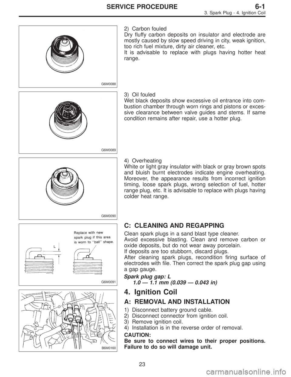
G6M0088
2) Carbon fouled
Dry fluffy carbon deposits on insulator and electrode are
mostly caused by slow speed driving in city, weak ignition,
too rich fuel mixture, dirty air cleaner, etc.
It is advisable to replace with plugs having hotter heat
range.
G6M0089
3) Oil fouled
Wet black deposits show excessive oil entrance into com-
bustion chamber through worn rings and pistons or exces-
sive clearance between valve guides and stems. If same
condition remains after repair, use a hotter plug.
G6M0090
4) Overheating
White or light gray insulator with black or gray brown spots
and bluish burnt electrodes indicate engine overheating.
Moreover, the appearance results from incorrect ignition
timing, loose spark plugs, wrong selection of fuel, hotter
range plug, etc. It is advisable to replace with plugs having
colder heat range.
G6M0091
C: CLEANING AND REGAPPING
Clean spark plugs in a sand blast type cleaner.
Avoid excessive blasting. Clean and remove carbon or
oxide deposits, but do not wear away porcelain.
If deposits are too stubborn, discard plugs.
After cleaning spark plugs, recondition firing surface of
electrodes with file. Then correct the spark plug gap using
a gap gauge.
Spark plug gap: L
1.0—1.1 mm (0.039—0.043 in)
B6M0160
4. Ignition Coil
A: REMOVAL AND INSTALLATION
1) Disconnect battery ground cable.
2) Disconnect connector from ignition coil.
3) Remove ignition coil.
4) Installation is in the reverse order of removal.
CAUTION:
Be sure to connect wires to their proper positions.
Failure to do so will damage unit.
23
6-1SERVICE PROCEDURE
3. Spark Plug - 4. Ignition Coil
Page 1096 of 2248
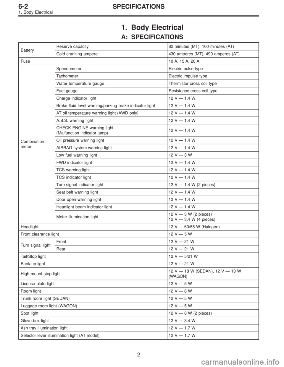
1. Body Electrical
A: SPECIFICATIONS
BatteryReserve capacity 82 minutes (MT), 100 minutes (AT)
Cold cranking ampere 430 amperes (MT), 490 amperes (AT)
Fuse10 A, 15 A, 20 A
Combination
meterSpeedometer Electric pulse type
Tachometer Electric impulse type
Water temperature gauge Thermistor cross coil type
Fuel gauge Resistance cross coil type
Charge indicator light 12 V—1.4 W
Brake fluid level warning/parking brake indicator light 12 V—1.4 W
AT oil temperature warning light (AWD only) 12 V—1.4 W
A.B.S. warning light 12 V—1.4 W
CHECK ENGINE warning light
(Malfunction indicator lamp)12 V—1.4 W
Oil pressure warning light 12 V—1.4 W
AIRBAG system warning light 12 V—1.4 W
Low fuel warning light 12 V—3W
FWD indicator light 12 V—1.4 W
TCS warning light 12 V—1.4 W
TCS indicator light 12 V—1.4 W
Turn signal indicator light 12 V—1.4 W (2 pieces)
Seat belt warning light 12 V—1.4 W
Door open warning light 12 V—1.4 W
Headlight beam indicator light 12 V—1.4 W
Meter illumination light12 V—3 W (2 pieces)
12 V—3.4 W (4 pieces)
Headlight 12 V—60/55 W (Halogen)
Front clearance light 12 V—5W
Turn signal lightFront 12 V—21 W
Rear 12 V—21 W
Tail/Stop light 12 V—5/21 W
Back-up light 12 V—21 W
High-mount stop light12 V—18 W (SEDAN), 12 V—13 W
(WAGON)
License plate light 12 V—5W
Room light 12 V—8W
Trunk room light (SEDAN) 12 V—5W
Luggage room light (WAGON) 12 V—5W
Spot light 12 V—8 W (2 pieces)
Glove box light 12 V—3.4 W
Ash tray illumination light 12 V—1.7 W
Selector lever illumination light (AT model) 12 V—1.7 W
2
6-2SPECIFICATIONS
1. Body Electrical
Page 1410 of 2248
OBD0265A
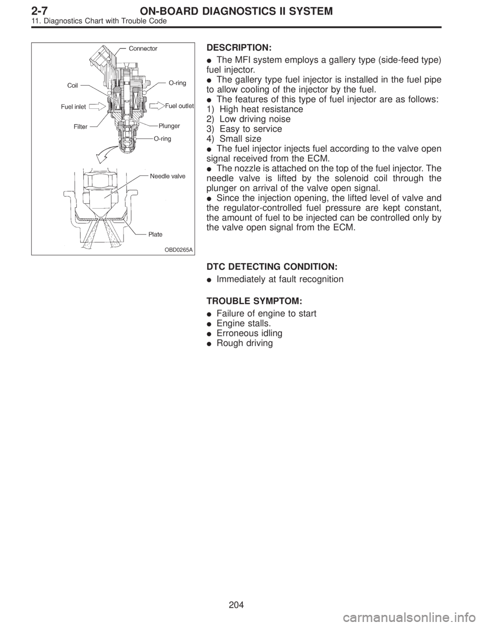
DESCRIPTION:
�The MFI system employs a gallery type (side-feed type)
fuel injector.
�The gallery type fuel injector is installed in the fuel pipe
to allow cooling of the injector by the fuel.
�The features of this type of fuel injector are as follows:
1) High heat resistance
2) Low driving noise
3) Easy to service
4) Small size
�The fuel injector injects fuel according to the valve open
signal received from the ECM.
�The nozzle is attached on the top of the fuel injector. The
needle valve is lifted by the solenoid coil through the
plunger on arrival of the valve open signal.
�Since the injection opening, the lifted level of valve and
the regulator-controlled fuel pressure are kept constant,
the amount of fuel to be injected can be controlled only by
the valve open signal from the ECM.
DTC DETECTING CONDITION:
�Immediately at fault recognition
TROUBLE SYMPTOM:
�Failure of engine to start
�Engine stalls.
�Erroneous idling
�Rough driving
204
2-7ON-BOARD DIAGNOSTICS II SYSTEM
11. Diagnostics Chart with Trouble Code
Page 1427 of 2248
OBD0292
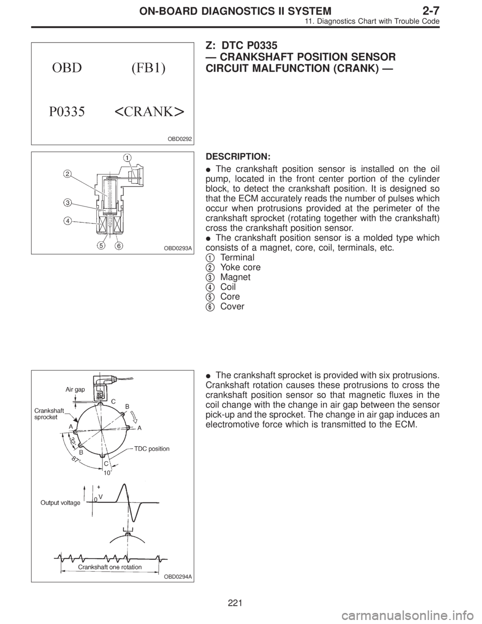
Z: DTC P0335
—CRANKSHAFT POSITION SENSOR
CIRCUIT MALFUNCTION (CRANK)—
OBD0293A
DESCRIPTION:
�The crankshaft position sensor is installed on the oil
pump, located in the front center portion of the cylinder
block, to detect the crankshaft position. It is designed so
that the ECM accurately reads the number of pulses which
occur when protrusions provided at the perimeter of the
crankshaft sprocket (rotating together with the crankshaft)
cross the crankshaft position sensor.
�The crankshaft position sensor is a molded type which
consists of a magnet, core, coil, terminals, etc.
�
1Terminal
�
2Yoke core
�
3Magnet
�
4Coil
�
5Core
�
6Cover
OBD0294A
�The crankshaft sprocket is provided with six protrusions.
Crankshaft rotation causes these protrusions to cross the
crankshaft position sensor so that magnetic fluxes in the
coil change with the change in air gap between the sensor
pick-up and the sprocket. The change in air gap induces an
electromotive force which is transmitted to the ECM.
221
2-7ON-BOARD DIAGNOSTICS II SYSTEM
11. Diagnostics Chart with Trouble Code