Page 190 of 2248
1. Precautions
WARNING:
�Place “No fire” signs near the working area.
�Disconnect ground terminal from battery.
�Be careful not to spill fuel on the floor.
G2M0340
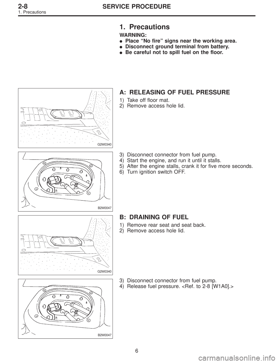
A: RELEASING OF FUEL PRESSURE
1) Take off floor mat.
2) Remove access hole lid.
B2M0047
3) Disconnect connector from fuel pump.
4) Start the engine, and run it until it stalls.
5) After the engine stalls, crank it for five more seconds.
6) Turn ignition switch OFF.
G2M0340
B: DRAINING OF FUEL
1) Remove rear seat and seat back.
2) Remove access hole lid.
B2M0047
3) Disconnect connector from fuel pump.
4) Release fuel pressure.
6
2-8SERVICE PROCEDURE
1. Precautions
Page 192 of 2248
B2M0049
11) On AWD model, after removing fuel sub meter unit,
drain fuel from there.
WARNING:
Do not use a motor pump when draining fuel.
2. On-Car Services
A: MEASUREMENT OF FUEL PRESSURE
1) Release fuel pressure.
2) Connect connector to fuel pump.
G2M0347
3) Disconnect fuel delivery hoses from fuel filter, and con-
nect fuel pressure gauge.
G2M0348
4) Start the engine.
5) Measure fuel pressure while disconnecting pressure
regulator vacuum hose from collector chamber.
Fuel pressure:
235 — 265 kPa (2.4 — 2.7 kg/cm
2, 34 — 38 psi)
6) After connecting pressure regulator vacuum hose, mea-
sure fuel pressure.
Fuel pressure:
177 — 206 kPa (1.8 — 2.1 kg/cm
2, 26 — 30 psi)
WARNING:
Before removing fuel pressure gauge, release fuel
pressure.
NOTE:
If out of specification as measured at step 6), check or
replace pressure regulator and pressure regulator vacuum
hose.
8
2-8SERVICE PROCEDURE
1. Precautions - 2. On-Car Services
Page 193 of 2248
B2M0049
11) On AWD model, after removing fuel sub meter unit,
drain fuel from there.
WARNING:
Do not use a motor pump when draining fuel.
2. On-Car Services
A: MEASUREMENT OF FUEL PRESSURE
1) Release fuel pressure.
2) Connect connector to fuel pump.
G2M0347
3) Disconnect fuel delivery hoses from fuel filter, and con-
nect fuel pressure gauge.
G2M0348
4) Start the engine.
5) Measure fuel pressure while disconnecting pressure
regulator vacuum hose from collector chamber.
Fuel pressure:
235 — 265 kPa (2.4 — 2.7 kg/cm
2, 34 — 38 psi)
6) After connecting pressure regulator vacuum hose, mea-
sure fuel pressure.
Fuel pressure:
177 — 206 kPa (1.8 — 2.1 kg/cm
2, 26 — 30 psi)
WARNING:
Before removing fuel pressure gauge, release fuel
pressure.
NOTE:
If out of specification as measured at step 6), check or
replace pressure regulator and pressure regulator vacuum
hose.
8
2-8SERVICE PROCEDURE
1. Precautions - 2. On-Car Services
Page 194 of 2248
G2M0345
3. Fuel Tank
A: REMOVAL
1) Release fuel pressure.
2) Drain fuel from fuel tank.
G2M0382
3) Remove rear exhaust pipe.
(1) Lift-up the vehicle.
(2) Separate rear exhaust pipe from center exhaust
pipe.
(3) Separate rear exhaust pipe from muffler.
(4) Remove bracket from rubber cushion, and remove
exhaust pipe.
NOTE:
To facilitate the removal of parts, apply a coat of SUBARU
CRC5-56 (Part No. 004301003)
G2M0384
4) Remove muffler assembly.
NOTE:
To facilitate the removal of parts, apply a coat of SUBARU
CRC5-56 (Part No. 004301003)
G3M0059
5) Remove rear differential assembly. (AWD model)
(1) Remove rear axle shafts from rear differential
assembly.
(2) Remove rear differential front cover.
(3) Remove propeller shaft.
(4) Remove lower differential bracket.
(5) Set transmission jack under rear differential.
(6) Remove bolts which install rear differential onto
rear crossmember.
9
2-8SERVICE PROCEDURE
3. Fuel Tank
Page 197 of 2248
G3M0059
6) Install rear differential assembly.
G2M0384
7) Install muffler assembly.
G2M0382
8) Install heat sealed cover.
9) Install rear exhaust pipe.
G2M0340
10) Lower the vehicle, and connect connector to fuel
pump.
11) Install access hole lid.
G2M0345
4. Fuel Filler Pipe
A: REMOVAL
1) Release fuel pressure.
2) Drain fuel from fuel tank.
12
2-8SERVICE PROCEDURE
3. Fuel Tank - 4. Fuel Filler Pipe
Page 198 of 2248
G3M0059
6) Install rear differential assembly.
G2M0384
7) Install muffler assembly.
G2M0382
8) Install heat sealed cover.
9) Install rear exhaust pipe.
G2M0340
10) Lower the vehicle, and connect connector to fuel
pump.
11) Install access hole lid.
G2M0345
4. Fuel Filler Pipe
A: REMOVAL
1) Release fuel pressure.
2) Drain fuel from fuel tank.
12
2-8SERVICE PROCEDURE
3. Fuel Tank - 4. Fuel Filler Pipe
Page 200 of 2248
G2M0358
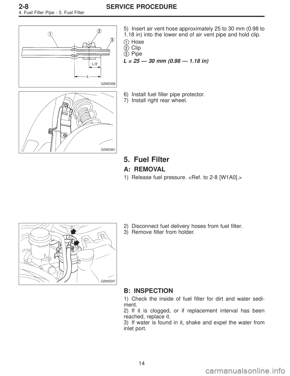
5) Insert air vent hose approximately 25 to 30 mm (0.98 to
1.18 in) into the lower end of air vent pipe and hold clip.
�
1Hose
�
2Clip
�
3Pipe
L=25—30 mm (0.98—1.18 in)
G2M0361
6) Install fuel filler pipe protector.
7) Install right rear wheel.
5. Fuel Filter
A: REMOVAL
1) Release fuel pressure.
G2M0347
2) Disconnect fuel delivery hoses from fuel filter.
3) Remove filter from holder.
B: INSPECTION
1) Check the inside of fuel filter for dirt and water sedi-
ment.
2) If it is clogged, or if replacement interval has been
reached, replace it.
3) If water is found in it, shake and expel the water from
inlet port.
14
2-8SERVICE PROCEDURE
4. Fuel Filler Pipe - 5. Fuel Filter
Page 201 of 2248
G2M0358
5) Insert air vent hose approximately 25 to 30 mm (0.98 to
1.18 in) into the lower end of air vent pipe and hold clip.
�
1Hose
�
2Clip
�
3Pipe
L=25—30 mm (0.98—1.18 in)
G2M0361
6) Install fuel filler pipe protector.
7) Install right rear wheel.
5. Fuel Filter
A: REMOVAL
1) Release fuel pressure.
G2M0347
2) Disconnect fuel delivery hoses from fuel filter.
3) Remove filter from holder.
B: INSPECTION
1) Check the inside of fuel filter for dirt and water sedi-
ment.
2) If it is clogged, or if replacement interval has been
reached, replace it.
3) If water is found in it, shake and expel the water from
inlet port.
14
2-8SERVICE PROCEDURE
4. Fuel Filler Pipe - 5. Fuel Filter
 On AWD model, after removing fuel sub meter unit,
drain fuel from there.
WARNING:
Do not use a motor pump when draining fuel.
2. On-Car Services
A: MEASUREMENT OF FUEL PRESSURE
1) Release")
 On AWD model, after removing fuel sub meter unit,
drain fuel from there.
WARNING:
Do not use a motor pump when draining fuel.
2. On-Car Services
A: MEASUREMENT OF FUEL PRESSURE
1) Release")
![SUBARU LEGACY 1995 Service Repair Manual G2M0345
3. Fuel Tank
A: REMOVAL
1) Release fuel pressure. <Ref. to 2-8 [W1A0].>
2) Drain fuel from fuel tank. <Ref. to 2-8 [W1B0].>
G2M0382
3) Remove rear exhaust pipe.
(1) Lift-up the vehicle.
(2) Se](/manual-img/17/57432/w960_57432-193.png "SUBARU LEGACY 1995 Service Repair Manual G2M0345
3. Fuel Tank
A: REMOVAL
1) Release fuel pressure. <Ref. to 2-8 [W1A0].>
2) Drain fuel from fuel tank. <Ref. to 2-8 [W1B0].>
G2M0382
3) Remove rear exhaust pipe.
(1) Lift-up the vehicle.
(2) Se")
![SUBARU LEGACY 1995 Service Repair Manual G3M0059
6) Install rear differential assembly. <Ref. to 3-4 [W2F0].>
G2M0384
7) Install muffler assembly.
G2M0382
8) Install heat sealed cover.
9) Install rear exhaust pipe.
G2M0340
10) Lower the vehi](/manual-img/17/57432/w960_57432-196.png "SUBARU LEGACY 1995 Service Repair Manual G3M0059
6) Install rear differential assembly. <Ref. to 3-4 [W2F0].>
G2M0384
7) Install muffler assembly.
G2M0382
8) Install heat sealed cover.
9) Install rear exhaust pipe.
G2M0340
10) Lower the vehi")
![SUBARU LEGACY 1995 Service Repair Manual G3M0059
6) Install rear differential assembly. <Ref. to 3-4 [W2F0].>
G2M0384
7) Install muffler assembly.
G2M0382
8) Install heat sealed cover.
9) Install rear exhaust pipe.
G2M0340
10) Lower the vehi](/manual-img/17/57432/w960_57432-197.png "SUBARU LEGACY 1995 Service Repair Manual G3M0059
6) Install rear differential assembly. <Ref. to 3-4 [W2F0].>
G2M0384
7) Install muffler assembly.
G2M0382
8) Install heat sealed cover.
9) Install rear exhaust pipe.
G2M0340
10) Lower the vehi")