Page 1334 of 2248

Throttle position sensor
Crankshaft position sensor & Camshaft p")
10. General Diagnostics Table
1. FOR ENGINE
12345678910111213
Problem parts
Mass air flow sensor
Engine coolant temperature sensor (*1)
Throttle position sensor
Crankshaft position sensor & Camshaft position sensor (*2)
Idle air control solenoid valve
Knock sensor
Purge control solenoid valve
EGR valve
Fuel injection parts (*3)
Ignition parts (*4)
Fuel pump and relay
A/C switch and A/C cut relay
Engine torque control signal circuitSymptom
1 Engine stalls during idling.�� � � ���
2 Rough idling�� � � � �
3 Engine does not return to idle.���
4 Poor acceleration�� � � ���
5Engine stalls or engine sags or hesi-
tates at acceleration.�� � � ��� �
6 Surge�� � �� �
7 Spark knock����
8 After burning in exhaust system�� � �
*1: The mark,�, indicates the symptom occurring only in cold temperatures.
*2: For items with the mark,�, ensure the secure installation of crankshaft position sensor and camshaft position sensor. Replacement is
not necessary.
*3: Check fuel injector, fuel pressure regulator and fuel filter.
*4: Check igniter, ignition coil and spark plug.
NOTE:
Malfunction of parts other than the above is also possible. Refer to 1. Engine Trouble in General [K100] in Repair Section 2-3 of the Ser-
vice Manual.
128
2-7ON-BOARD DIAGNOSTICS II SYSTEM
10. General Diagnostics Table
Page 1339 of 2248
 LIST
DTC
No.Abbreviation
(Subaru select monitor)Item Page
P0100 QA Mass air flow sensor circuit malfunction 135
P0101 QA
—R M")
11. Diagnostics Chart with Trouble
Code
A: DIAGNOSTIC TROUBLE CODE (DTC) LIST
DTC
No.Abbreviation
(Subaru select monitor)Item Page
P0100 QA Mass air flow sensor circuit malfunction 135
P0101 QA
—R Mass air flow sensor circuit range/performance problem 141
P0105 P
—S Pressure sensor circuit malfunction 144
P0106 P
—R Pressure sensor circuit range/performance problem 151
P0115 TW Engine coolant temperature sensor circuit malfunction 156
P0120 THV Throttle position sensor circuit malfunction 161
P0121 TH
—R Throttle position sensor circuit range/performance problem 167
P0125 TW
—CL Insufficient coolant temperature for closed loop fuel control 169
P0130 FO2
—V Front oxygen sensor circuit malfunction 171
P0133 FO2
—R Front oxygen sensor circuit slow response 177
P0135 FO2H Front oxygen sensor heater circuit malfunction 180
P0136 RO2
—V Rear oxygen sensor circuit malfunction 185
P0139 RO2
—R Rear oxygen sensor circuit slow response 190
P0141 RO2H Rear oxygen sensor heater circuit malfunction 193
P0170 FUEL Fuel trim malfunction 198
P0201 INJ1 Fuel injector circuit malfunction - #1
203 P0202 INJ2 Fuel injector circuit malfunction - #2
P0203 INJ3 Fuel injector circuit malfunction - #3
P0204 INJ4 Fuel injector circuit malfunction - #4
P0301 MIS
—1 Cylinder 1 misfire detected
210 P0302 MIS
—2 Cylinder 2 misfire detected
P0303 MIS
—3 Cylinder 3 misfire detected
P0304 MIS
—4 Cylinder 4 misfire detected
P0325 KNOCK Knock sensor circuit malfunction 217
P0335 CRANK Crankshaft position sensor circuit malfunction 221
P0340 CAM Camshaft position sensor circuit malfunction 225
P0400 EGR Exhaust gas recirculation flow malfunction 229
P0403 EGRSOL Exhaust gas recirculation circuit malfunction 235
P0420 CAT Catalyst system efficiency below threshold 240
P0441 CPC
—F Evaporative emission control system incorrect purge flow 244
P0443 CPC Evaporative emission control system purge control valve circuit malfunction 248
P0500 VSP Vehicle speed sensor malfunction 253
P0505 ISC Idle control system malfunction 256
P0506 ISC
—L Idle control system RPM lower than expected 262
P0507 ISC
—H Idle control system RPM higher than expected 264
P0600—Serial communication link malfunction 266
P0601 RAM Internal control module memory check sum error 268
P0703 BRK Brake switch input malfunction 271
133
2-7ON-BOARD DIAGNOSTICS II SYSTEM
11. Diagnostics Chart with Trouble Code
Page 1404 of 2248
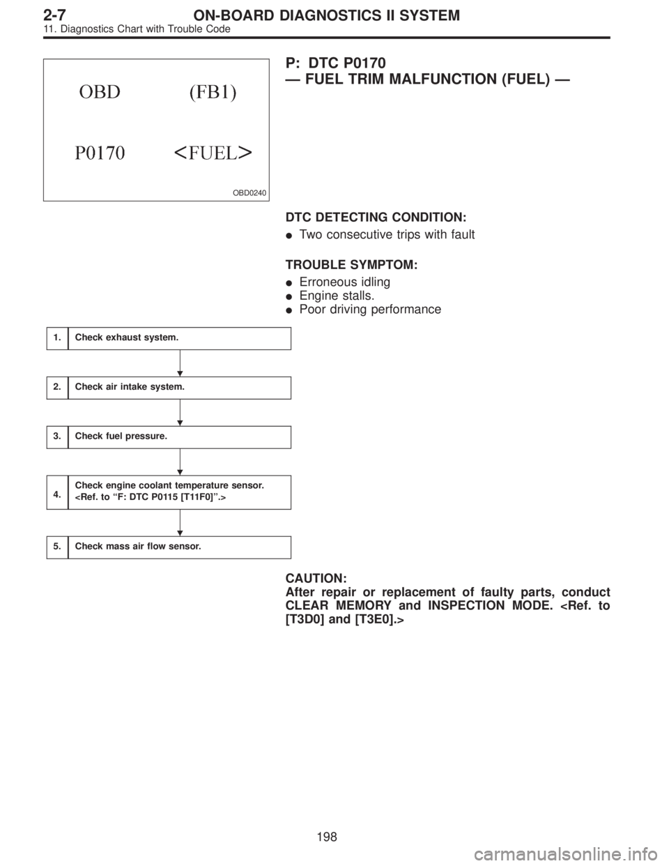
OBD0240
P: DTC P0170
—FUEL TRIM MALFUNCTION (FUEL)—
DTC DETECTING CONDITION:
�Two consecutive trips with fault
TROUBLE SYMPTOM:
�Erroneous idling
�Engine stalls.
�Poor driving performance
1.Check exhaust system.
2.Check air intake system.
3.Check fuel pressure.
4.Check engine coolant temperature sensor.
5.Check mass air flow sensor.
CAUTION:
After repair or replacement of faulty parts, conduct
CLEAR MEMORY and INSPECTION MODE.
[T3D0] and [T3E0].>
�
�
�
�
198
2-7ON-BOARD DIAGNOSTICS II SYSTEM
11. Diagnostics Chart with Trouble Code
Page 1405 of 2248
1
CHECK EXHAUST SYSTEM.
: Are there holes or loose bolts on exhaust
system?
: Repair exhaust system.
: Go to step 2.
2
CHECK AIR INTAKE SYSTEM.
: Are there holes, loose bolts or disconnec-
tion of hose on air intake system?
: Repair air intake system.
: Go to step 3.
B2M0047
3
CHECK FUEL PRESSURE.
1) Release fuel pressure.
(1) Remove fuel pump access hole lid located on the
right rear of trunk compartment floor (Sedan) or lug-
gage compartment floor (Wagon).
(2) Disconnect connector from fuel tank.
(3) Start the engine, and run it until it stalls.
(4) After stopping the engine, crank the engine for 5 to
7 seconds to reduce fuel pressure.
(5) Turn ignition switch to OFF.
B2M0047
2) Connect connector to fuel tank.
199
2-7ON-BOARD DIAGNOSTICS II SYSTEM
11. Diagnostics Chart with Trouble Code
Page 1406 of 2248
 Disconnect fuel delivery hose from fuel filter, and con-
nect fuel pressure gauge.
G2M0348
4) Start the engine and idle while gear position is neutral.
5) Measure fuel pressure while discon")
OBD0711
3) Disconnect fuel delivery hose from fuel filter, and con-
nect fuel pressure gauge.
G2M0348
4) Start the engine and idle while gear position is neutral.
5) Measure fuel pressure while disconnecting pressure
regulator vacuum hose from intake manifold.
: Fuel pressure:
226—275 kPa (2.3—2.8 kg/cm2,
33—40 psi)
: Go to next step.
: Repair the following items.
Fuel pressure too high�Clogged fuel return line or bent
hose
Fuel pressure too low�Improper fuel pump discharge
�Clogged fuel supply line
6) After connecting pressure regulator vacuum hose, mea-
sure fuel pressure.
: Fuel pressure:
157—206 kPa (1.6—2.1 kg/cm2,
23—30 psi)
: Go to step 4.
: Repair the following items.
Fuel pressure too high�Faulty pressure regulator
�Clogged fuel return line or bent
hose
Fuel pressure too low�Faulty pressure regulator
�Improper fuel pump discharge
�Clogged fuel supply line
WARNING:
Before removing fuel pressure gauge, release fuel
pressure.
NOTE:
�If fuel pressure does not increase, squeeze fuel return
hose 2 to 3 times, then measure fuel pressure again.
�If out of specification as measured at step 6), check or
replace pressure regulator and pressure regulator vacuum
hose.
200
2-7ON-BOARD DIAGNOSTICS II SYSTEM
11. Diagnostics Chart with Trouble Code
Page 1410 of 2248

fuel injector.
�The gallery type fuel injector is installed in the fuel pipe
to allow cooling of the injector by the fuel.")
OBD0265A
DESCRIPTION:
�The MFI system employs a gallery type (side-feed type)
fuel injector.
�The gallery type fuel injector is installed in the fuel pipe
to allow cooling of the injector by the fuel.
�The features of this type of fuel injector are as follows:
1) High heat resistance
2) Low driving noise
3) Easy to service
4) Small size
�The fuel injector injects fuel according to the valve open
signal received from the ECM.
�The nozzle is attached on the top of the fuel injector. The
needle valve is lifted by the solenoid coil through the
plunger on arrival of the valve open signal.
�Since the injection opening, the lifted level of valve and
the regulator-controlled fuel pressure are kept constant,
the amount of fuel to be injected can be controlled only by
the valve open signal from the ECM.
DTC DETECTING CONDITION:
�Immediately at fault recognition
TROUBLE SYMPTOM:
�Failure of engine to start
�Engine stalls.
�Erroneous idling
�Rough driving
204
2-7ON-BOARD DIAGNOSTICS II SYSTEM
11. Diagnostics Chart with Trouble Code
Page 1422 of 2248
�5GROUP OF #2 AND #4 CYLINDERS
: Check the following items for #2 and #4 cyl-
inders.
�Spark plugs
�Fuel injectors
�Skipping timing belt teeth
�
6THE CYLINDER AT RANDOM
: Is the engine idle rough?
: Go to next. (AT models only)
: Go to DTC P0170 [T11P3], [T11P4] and [T11P5].
NOTE:
On MT models, go to DTC P0170 [T11P3], [T11P4] and
[T11P5].
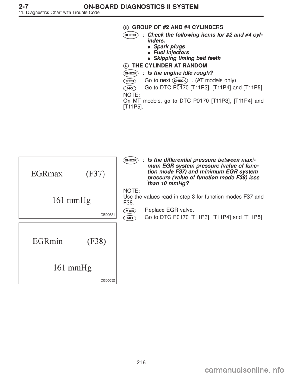
OBD0631
OBD0632
: Is the differential pressure between maxi-
mum EGR system pressure (value of func-
tion mode F37) and minimum EGR system
pressure (value of function mode F38) less
than 10 mmHg?
NOTE:
Use the values read in step 3 for function modes F37 and
F38.
: Replace EGR valve.
: Go to DTC P0170 [T11P3], [T11P4] and [T11P5].
216
2-7ON-BOARD DIAGNOSTICS II SYSTEM
11. Diagnostics Chart with Trouble Code
Page 1990 of 2248
![SUBARU LEGACY 1995 Service Repair Manual 7. Electrical Unit Location
Electrical unit Refer to;
A.B.S. control module 4-4a [T300]
A.B.S. G sensor (MT) 4-4a [T300]
A/C compressor relay�
7
A/C fuse�11
A/C main fan relay 1�10
A/C main fan relay](/manual-img/17/57432/w960_57432-1989.png "SUBARU LEGACY 1995 Service Repair Manual 7. Electrical Unit Location
Electrical unit Refer to;
A.B.S. control module 4-4a [T300]
A.B.S. G sensor (MT) 4-4a [T300]
A/C compressor relay�
7
A/C fuse�11
A/C main fan relay 1�10
A/C main fan relay")
7. Electrical Unit Location
Electrical unit Refer to;
A.B.S. control module 4-4a [T300]
A.B.S. G sensor (MT) 4-4a [T300]
A/C compressor relay�
7
A/C fuse�11
A/C main fan relay 1�10
A/C main fan relay 2�8
A/C pressure switch�2
A/C sub fan relay 2�9
ATF temperature sensor 2-7 [T2B1]
Blower motor resistor�
26
Blower relay�13
Camshaft position sensor 2-7 [T2A2]
Check connector�
25
Clutch switch (MT) 6-2 [T300]
Crankshaft position sensor 2-7 [T2A2]
Cruise control module 6-2 [T300]
Cruise control pump 6-2 [T300]
Data link connector (for OBD-II G.S.T.) 2-7 [T2A1]
Data link connector (for S.S.M.) 2-7 [T2A1]
Diagnosis connector 4-4a [T300]
Diagnosis terminal (Ground) 4-4a [T300]
Door lock timer�
27
Engine control module 2-7 [T2A1]
Engine coolant temperature sensor 2-7 [T2A2]
Engine hood switch (Security) 6-2 [K6A0]
Evaporator thermoswitch�
29
F/B�15
FRESH/RECIRC actuator�28
Fuel pump relay 2-7 [T2A3]
Fuel gauge module�
31
Fuel gauge sub module (AWD)�32
FWD switch (AT)�1
Headlight alarm relay (Security) 6-2 [K6A0]
Headlight relay LH�
5
Headlight relay RH�6
Horn relay�14
Electrical unit Refer to;
Hydraulic unit (A.B.S.) 4-4a [T300]
Ignition coil 2-7 [T2A3]
Ignitor 2-7 [T2A3]
Idle air control solenoid valve 2-7 [T2A3]
Illumination control module�
21
Inhibitor switch 6-2 [T300]
Knock sensor 2-7 [T2A2]
Main fan relay�
19
Main relay 2-7 [T2A3]
Mass air flow sensor 2-7 [T2A2]
Mode actuator�
12
M/B�4
Oil pressure switch�3
Oxygen sensor 2-7 [T2A2]
Pedal stroke sensor (T.C.S.) 4-4b [T300]
Power window and sunroof relay�
24
Power window circuit breaker�23
Purge control solenoid valve 2-7 [T2A3]
Rear defogger relay�
17
Seat belt timer�20
Security control module 6-2 [K6A0]
Shift lock control module�
22
Starter interrupt relay (Security) 6-2 [K6A0]
Stop & brake switch (With cruise con-
trol)6-2 [T300]
Sunroof control module�
30
Tail and illumination relay�18
T.C.S. control module 4-4b [T300]
T.C.S. motor relay 4-4b [T300]
T.C.S. valve relay 4-4b [T300]
Throttle position sensor 2-7 [T2A2]
Test mode connector 2-7 [T2A1]
Transmission control module 2-7 [T2B1]
Turn & hazard module�
16
Vehicle speed sensor 1 2-7 [T2B1]
Vehicle speed sensor 2 2-7 [T2B1]
104
6-3WIRING DIAGRAM
7. Electrical Unit Location